Page is loading ...

User’s Manual
Extron Electronics, USA
1230 South Lewis Street
Anaheim, CA 92805
800.633.9876 714.491.1500
FAX 714.491.1517
Extron Electronics, Europe
Beeldschermweg 6C
3821 AH Amersfoort, The Netherlands
+800.3987.6673 +31.33.453.4040
FAX +31.33.453.4050
Extron Electronics, Asia
135 Joo Seng Rd. #04-01
PM Industrial Bldg., Singapore 368363
+800.7339.8766 +65.6383.4400
FAX +65.6383.4664
Extron Electronics, Japan
Kyodo Building, 16 Ichibancho
Chiyoda-ku, Tokyo 102-0082
Japan
+81.3.3511.7655 FAX +81.3.3511.7656
www.extron.com
© 2007 Extron Electronics. All rights reserved.
Remote Control Panels
68-1069-01 Rev. C
04 07
MKP 3000 Series

Precautions
This symbol is intended to alert the user of important
operating and maintenance (servicing) instructions
in the literature provided with the equipment.
This symbol is intended to alert the user of the
presence of uninsulated dangerous voltage within
the product's enclosure that may present a risk of
electric shock.
Caution
Read Instructions • Read and understand all safety and operating
instructions before using the equipment.
Retain Instructions • The safety instructions should be kept for future
reference.
Follow Warnings • Follow all warnings and instructions marked on the
equipment or in the user information.
Avoid Attachments • Do not use tools or attachments that are not
recommended by the equipment manufacturer because they may be
hazardous.
Warning
Power sources • This equipment should be operated only from the power source
indicated on the product. This equipment is intended to be used with a main
power system with a grounded (neutral) conductor. The third (grounding) pin is
a safety feature, do not attempt to bypass or disable it.
Power disconnection • To remove power from the equipment safely, remove all
power cords from the rear of the equipment, or the desktop power module (if
detachable), or from the power source receptacle (wall plug).
Power cord protection • Power cords should be routed so that they are not likely to
be stepped on or pinched by items placed upon or against them.
Servicing • Refer all servicing to qualified service personnel. There are no user-
serviceable parts inside. To prevent the risk of shock, do not attempt to service
this equipment yourself because opening or removing covers may expose you to
dangerous voltage or other hazards.
Slots and openings • If the equipment has slots or holes in the enclosure, these are
provided to prevent overheating of sensitive components inside. These openings
must never be blocked by other objects.
Lithium battery • There is a danger of explosion if battery is incorrectly replaced.
Replace it only with the same or equivalent type recommended by the
manufacturer. Dispose of used batteries according to the manufacturer's
instructions.
Ce symbole sert à avertir l’utilisateur que la
documentation fournie avec le matériel contient des
instructions importantes concernant l’exploitation
et la maintenance (réparation).
Ce symbole sert à avertir l’utilisateur de la présence
dans le boîtier de l’appareil de tensions dangereuses
non isolées posant des risques d’électrocution.
Attention
Lire les instructions• Prendre connaissance de toutes les consignes de
sécurité et d’exploitation avant d’utiliser le matériel.
Conserver les instructions• Ranger les consignes de sécurité afin de
pouvoir les consulter à l’avenir.
Respecter les avertissements • Observer tous les avertissements et
consignes marqués sur le matériel ou présentés dans la documentation
utilisateur.
Eviter les pièces de fixation • Ne pas utiliser de pièces de fixation ni
d’outils non recommandés par le fabricant du matériel car cela
risquerait de poser certains dangers.
Avertissement
Alimentations• Ne faire fonctionner ce matériel qu’avec la source d’alimentation
indiquée sur l’appareil. Ce matériel doit être utilisé avec une alimentation
principale comportant un fil de terre (neutre). Le troisième contact (de mise à la
terre) constitue un dispositif de sécurité : n’essayez pas de la contourner ni de la
désactiver.
Déconnexion de l’alimentation• Pour mettre le matériel hors tension sans danger,
déconnectez tous les cordons d’alimentation de l’arrière de l’appareil ou du
module d’alimentation de bureau (s’il est amovible) ou encore de la prise secteur.
Protection du cordon d’alimentation • Acheminer les cordons d’alimentation de
manière à ce que personne ne risque de marcher dessus et à ce qu’ils ne soient
pas écrasés ou pincés par des objets.
Réparation-maintenance • Faire exécuter toutes les interventions de réparation-
maintenance par un technicien qualifié. Aucun des éléments internes ne peut être
réparé par l’utilisateur. Afin d’éviter tout danger d’électrocution, l’utilisateur ne
doit pas essayer de procéder lui-même à ces opérations car l’ouverture ou le
retrait des couvercles risquent de l’exposer à de hautes tensions et autres dangers.
Fentes et orifices • Si le boîtier de l’appareil comporte des fentes ou des orifices,
ceux-ci servent à empêcher les composants internes sensibles de surchauffer. Ces
ouvertures ne doivent jamais être bloquées par des objets.
Lithium Batterie • Il a danger d'explosion s'll y a remplacment incorrect de la
batterie. Remplacer uniquement avec une batterie du meme type ou d'un ype
equivalent recommande par le constructeur. Mettre au reut les batteries usagees
conformement aux instructions du fabricant.
Safety Instructions • English
Consignes de Sécurité • Français
Sicherheitsanleitungen • Deutsch
Dieses Symbol soll dem Benutzer in der im
Lieferumfang enthaltenen Dokumentation
besonders wichtige Hinweise zur Bedienung und
Wartung (Instandhaltung) geben.
Dieses Symbol soll den Benutzer darauf aufmerksam
machen, daß im Inneren des Gehäuses dieses
Produktes gefährliche Spannungen, die nicht isoliert
sind und die einen elektrischen Schock verursachen
können, herrschen.
Achtung
Lesen der Anleitungen • Bevor Sie das Gerät zum ersten Mal verwenden,
sollten Sie alle Sicherheits-und Bedienungsanleitungen genau
durchlesen und verstehen.
Aufbewahren der Anleitungen • Die Hinweise zur elektrischen Sicherheit
des Produktes sollten Sie aufbewahren, damit Sie im Bedarfsfall darauf
zurückgreifen können.
Befolgen der Warnhinweise • Befolgen Sie alle Warnhinweise und
Anleitungen auf dem Gerät oder in der Benutzerdokumentation.
Keine Zusatzgeräte • Verwenden Sie keine Werkzeuge oder Zusatzgeräte,
die nicht ausdrücklich vom Hersteller empfohlen wurden, da diese eine
Gefahrenquelle darstellen können.
Vorsicht
Stromquellen • Dieses Gerät sollte nur über die auf dem Produkt angegebene
Stromquelle betrieben werden. Dieses Gerät wurde für eine Verwendung mit
einer Hauptstromleitung mit einem geerdeten (neutralen) Leiter konzipiert. Der
dritte Kontakt ist für einen Erdanschluß, und stellt eine Sicherheitsfunktion dar.
Diese sollte nicht umgangen oder außer Betrieb gesetzt werden.
Stromunterbrechung • Um das Gerät auf sichere Weise vom Netz zu trennen,
sollten Sie alle Netzkabel aus der Rückseite des Gerätes, aus der externen
Stomversorgung (falls dies möglich ist) oder aus der Wandsteckdose ziehen.
Schutz des Netzkabels • Netzkabel sollten stets so verlegt werden, daß sie nicht
im Weg liegen und niemand darauf treten kann oder Objekte darauf- oder
unmittelbar dagegengestellt werden können.
Wartung • Alle Wartungsmaßnahmen sollten nur von qualifiziertem
Servicepersonal durchgeführt werden. Die internen Komponenten des Gerätes
sind wartungsfrei. Zur Vermeidung eines elektrischen Schocks versuchen Sie in
keinem Fall, dieses Gerät selbst öffnen, da beim Entfernen der Abdeckungen die
Gefahr eines elektrischen Schlags und/oder andere Gefahren bestehen.
Schlitze und Öffnungen • Wenn das Gerät Schlitze oder Löcher im Gehäuse
aufweist, dienen diese zur Vermeidung einer Überhitzung der empfindlichen
Teile im Inneren. Diese Öffnungen dürfen niemals von anderen Objekten
blockiert werden.
Litium-Batterie • Explosionsgefahr, falls die Batterie nicht richtig ersetzt wird.
Ersetzen Sie verbrauchte Batterien nur durch den gleichen oder einen
vergleichbaren Batterietyp, der auch vom Hersteller empfohlen wird. Entsorgen
Sie verbrauchte Batterien bitte gemäß den Herstelleranweisungen.
Este símbolo se utiliza para advertir al usuario sobre
instrucciones importantes de operación y
mantenimiento (o cambio de partes) que se desean
destacar en el contenido de la documentación
suministrada con los equipos.
Este símbolo se utiliza para advertir al usuario sobre
la presencia de elementos con voltaje peligroso sin
protección aislante, que puedan encontrarse dentro
de la caja o alojamiento del producto, y que puedan
representar riesgo de electrocución.
Precaucion
Leer las instrucciones • Leer y analizar todas las instrucciones de
operación y seguridad, antes de usar el equipo.
Conservar las instrucciones • Conservar las instrucciones de seguridad
para futura consulta.
Obedecer las advertencias • Todas las advertencias e instrucciones
marcadas en el equipo o en la documentación del usuario, deben ser
obedecidas.
Evitar el uso de accesorios • No usar herramientas o accesorios que no
sean especificamente recomendados por el fabricante, ya que podrian
implicar riesgos.
Advertencia
Alimentación eléctrica • Este equipo debe conectarse únicamente a la fuente/tipo
de alimentación eléctrica indicada en el mismo. La alimentación eléctrica de este
equipo debe provenir de un sistema de distribución general con conductor
neutro a tierra. La tercera pata (puesta a tierra) es una medida de seguridad, no
puentearia ni eliminaria.
Desconexión de alimentación eléctrica • Para desconectar con seguridad la
acometida de alimentación eléctrica al equipo, desenchufar todos los cables de
alimentación en el panel trasero del equipo, o desenchufar el módulo de
alimentación (si fuera independiente), o desenchufar el cable del receptáculo de
la pared.
Protección del cables de alimentación • Los cables de alimentación eléctrica se
deben instalar en lugares donde no sean pisados ni apretados por objetos que se
puedan apoyar sobre ellos.
Reparaciones/mantenimiento • Solicitar siempre los servicios técnicos de personal
calificado. En el interior no hay partes a las que el usuario deba acceder. Para
evitar riesgo de electrocución, no intentar personalmente la reparación/
mantenimiento de este equipo, ya que al abrir o extraer las tapas puede quedar
expuesto a voltajes peligrosos u otros riesgos.
Ranuras y aberturas • Si el equipo posee ranuras o orificios en su caja/alojamiento,
es para evitar el sobrecalientamiento de componentes internos sensibles. Estas
aberturas nunca se deben obstruir con otros objetos.
Batería de litio • Existe riesgo de explosión si esta batería se coloca en la posición
incorrecta. Cambiar esta batería únicamente con el mismo tipo (o su equivalente)
recomendado por el fabricante. Desachar las baterías usadas siguiendo las
instrucciones del fabricante.
Instrucciones de seguridad • Español
Extron’s Warranty
Extron Electronics warrants this product against defects in materials and
workmanship for a period of three years from the date of purchase. In the event of
malfunction during the warranty period attributable directly to faulty workmanship
and/or materials, Extron Electronics will, at its option, repair or replace said products
or components, to whatever extent it shall deem necessary to restore said product to
proper operating condition, provided that it is returned within the warranty period,
with proof of purchase and description of malfunction to:
USA, Canada, South America, Europe, Africa, and the Middle East:
and Central America:
Extron Electronics, Europe
Extron Electronics Beeldschermweg 6C
1001 East Ball Road 3821 AH Amersfoort
Anaheim, CA 92805, USA The Netherlands
Asia: Japan:
Extron Electronics, Asia Extron Electronics, Japan
135 Joo Seng Road, #04-01 Kyodo Building
PM Industrial Bldg. 16 Ichibancho
Singapore 368363 Chiyoda-ku, Tokyo 102-0082
Japan
This Limited Warranty does not apply if the fault has been caused by misuse,
improper handling care, electrical or mechanical abuse, abnormal operating conditions
or non-Extron authorized modification to the product.
If it has been determined that the product is defective, please call Extron and ask for an
Applications Engineer at (714) 491-1500 (USA), 31.33.453.4040 (Europe), 65.6383.4400
(Asia), or 81.3.3511.7655 (Japan) to receive an RA# (Return Authorization number). This
will begin the repair process as quickly as possible.
Units must be returned insured, with shipping charges prepaid. If not insured, you
assume the risk of loss or damage during shipment. Returned units must include the
serial number and a description of the problem, as well as the name of the person to
contact in case there are any questions.
Extron Electronics makes no further warranties either expressed or implied with
respect to the product and its quality, performance, merchantability, or fitness for any
particular use. In no event will Extron Electronics be liable for direct, indirect, or
consequential damages resulting from any defect in this product even if Extron
Electronics has been advised of such damage.
Please note that laws vary from state to state and country to country, and that some
provisions of this warranty may not apply to you.

ᅝܼ乏ⶹ噝Ё᭛
ᅝܼ乏ⶹ噝Ё᭛
䖭Ͼヺোᦤ⼎⫼᠋䆹䆒⫼᠋ݠЁ
ⱘ᪡㓈ᡸ䇈ᯢDŽ
䖭Ͼヺো䄺ਞ⫼᠋䆹䆒ᴎݙᲈ
䴆ⱘॅ䰽⬉य़ˈ᳝㾺⬉ॅ䰽DŽ
⊼ᛣ
⊼ᛣ
䯙䇏䇈ᯢк
䯙䇏䇈ᯢк
噝⫼᠋Փ⫼䆹䆒ࠡᖙ乏䯙䇏ᑊ⧚㾷
᳝ᅝܼՓ⫼䇈ᯢDŽ
ֱᄬ䇈ᯢк
ֱᄬ䇈ᯢк
噝⫼᠋ᑨֱᄬᅝܼ䇈ᯢкҹᇚᴹՓ⫼DŽ
䙉ᅜ䄺ਞ噝⫼᠋ᑨ䙉ᅜѻક⫼᠋ᣛफϞⱘ᠔᳝
ᅝܼ᪡䇈ᯢDŽ
䙓ܡ䗑ࡴ
䙓ܡ䗑ࡴ
噝ϡ㽕Փ⫼䆹ѻકॖଚ≵᳝㤤ⱘᎹ
䗑ࡴ䆒ˈҹ䙓ܡॅ䰽DŽ
䄺ਞ
䄺ਞ
⬉⑤
⬉⑤
噝䆹䆒া㛑Փ⫼ѻકϞᷛᯢⱘ⬉⑤DŽ䆒ᖙ⫼᳝
ഄ㒓կ⬉㋏㒳կ⬉DŽϝᴵ㒓˄ഄ㒓˅ᰃᅝ䆒ᮑˈϡ㛑ϡ
⫼䏇䖛DŽ
ᢨᥝ⬉⑤
ᢨᥝ⬉⑤
噝ЎᅝܼഄҢ䆒ᢨᥝ⬉⑤ˈ䇋ᢨᥝ᠔᳝
ৢḠ䴶⬉⑤ⱘ⬉⑤㒓ˈӏԩࠄᏖ⬉㋏㒳
⬉⑤㒓DŽ
⬉⑤㒓ֱᡸ
⬉⑤㒓ֱᡸ
噝ཹᏗ㒓ˈ䙓ܡ㹿䏽䏣ˈ䞡⠽य़DŽ
㓈ᡸ
㓈ᡸ
噝᠔᳝㓈ׂᖙ乏⬅䅸䆕ⱘ㓈ׂҎਬ䖯㸠DŽ䆒
䚼≵᳝⫼᠋ৃҹᤶⱘ䳊ӊDŽЎ䙓ܡߎ⦄㾺⬉ॅ
ϡ㽕㞾Ꮕ䆩ᠧᓔ䆒Ⲫᄤ㓈ׂ䆹䆒DŽ
䗮亢ᄨ
䗮亢ᄨ
噝᳝ѯ䆒ᴎϞ᳝䗮亢ῑᄨˈᅗӀᰃ⫼
䰆ℶᴎݙᬣᛳܗӊ䖛⛁DŽϡ㽕⫼ӏԩϰ㽓ᣵԣ䗮亢ᄨDŽ
䫖⬉∴
䫖⬉∴
噝ϡℷ⹂ⱘᤶ⬉∴Ӯ᳝⟚⚌ⱘॅ䰽DŽᖙ乏Փ
Ϣॖᆊ㤤ⱘⳌৠⳌ䖥ൟোⱘ⬉∴DŽᣝ✻⫳ѻॖⱘ
䆂໘⧚ᑳᓗ⬉∴
DŽ
FCC Class A Notice
This equipment has been tested and found to comply with the limits for a
Class A digital device, pursuant to part 15 of the FCC Rules. These limits are designed
to provide reasonable protection against harmful interference when the equipment is
operated in a commercial environment. This equipment generates, uses and can
radiate radio frequency energy and, if not installed and used in accordance with the
instruction manual, may cause harmful interference to radio communications.
Operation of this equipment in a residential area is likely to cause harmful
interference, in which case the user will be required to correct the interference at his
own expense.
This unit was tested with shielded cables on the peripheral devices.
Shielded cables must be used with the unit to ensure compliance.
This device complies with Part 15 of the FCC Rules. Operation is subject to the
following two conditions: (1) this device may not cause harmful interference, and
(2) this device must accept any interference received, including interference that may
cause undesired operation.

Precautions, cont’d
MKP 3000 Series • Quick Start Guide
Quick Start Guide — MKP 3000
QS-1
Install and set up the MKP 3000 as follows:
Step 1
Turn all of the equipment off or disconnect it from its power source.
Step 2
Install the cables that will run to and from the control panel in a
wall, podium, or desk.
Step 3
Prepare the wall, podium, desk, or other surface to mount the MKP.
See “Preparing the site and installing the mounting bracket (mud
ring) or wall box” in chapter 2, “Installation.”
Step 4
Install the control panel in a wall, podium, desk, or other surface.
See “Installation Procedures” in chapter 2, “Installation.”
Step 5
Connect the input and output cables. See “Rear Panel and Side
Panel Connections” in chapter 2, “Installation,” for guidelines.
Step 6
Connect the power supply. See “Power supply wiring” in chapter 2,
“Installation.”
Step 7
Connect power cords and turn on the equipment in the following
order: output devices (such as projectors or monitors), the connected
matrix switcher, and input devices (such as DSSs or cable boxes).
Step 8
If necessary, set the IP parameters of the control panel and matrix
switcher. See “Viewing and configuring the IP and MKP setup
parameters” in chapter 3, “Local Operation;” or “System Settings
page” in chapter 5, “HTML Operation.”
Step 9
If necessary, set the control panel’s RS-232 port for pass-through or
no-pass-through mode, and specify whether the MKP is the primary
device (connected to the switcher) or secondary device (connected
through another device). See “Viewing and configuring the IP and
MKP setup parameters” in chapter 3, “Local Operation,” or “System
Settings page” in chapter 5, “HTML Operation.”

MKP 3000 Series • Quick Start Guide
Quick Start Guide — MKP 3000, cont’d
iMKP 3000 Series • Table of Contents
Chapter 1 • Introduction .......................................................... 1-1
About this Manual ................................................................ 1-2
About the MKP 3000 Series Remote Control
Panels
........................................................................................... 1-2
Setup examples ...................................................................... 1-3
RS-232 connection to the switcher ....................................... 1-4
Ethernet connection to the switcher ................................... 1-4
Application diagram.............................................................. 1-4
Chapter 2 • Installation ............................................................. 2-1
MKP Installation Overview............................................... 2-2
Installation Procedures....................................................... 2-3
Preparing the site .................................................................. 2-3
UL requirements for wall box installation ........................... 2-4
Installing a mounting bracket (mud ring) or wall box ........ 2-4
Mounting the MKP to a mud ring or wall box .................... 2-7
Mounting the MKP 3000 L .................................................... 2-8
Mounting the MKP 3000 L in a lectern .......................... 2-8
Mounting the MKP 3000 L in a rack ............................... 2-8
UL requirements for rack mounting ............................... 2-9
Rear Panel and Side Panel Connections .................. 2-10
Control connections ............................................................ 2-13
RS-232 connection ......................................................... 2-13
RS-232 cable termination .............................................. 2-14
Ethernet connection ...................................................... 2-15
Ethernet (TP) cable termination ................................... 2-16
Power supply wiring ............................................................ 2-18
Mounting the MKP 10 MAAP ......................................... 2-19
Chapter 3 • Local Operation .................................................. 3-1
Front Panel Controls and Indications ......................... 3-2
Front Panel Operations....................................................... 3-4
Changing the tie mode ......................................................... 3-4
Creating ties ........................................................................... 3-5
Creating a tie in matrix mode (default) ......................... 3-5
Creating a tie in input-only mode .................................. 3-7
Deselecting a tie .............................................................. 3-8
Viewing ties ........................................................................... 3-9
Selecting a preset ................................................................ 3-10
Adjusting the audio output ................................................ 3-10
Table of Contents
QS-2
Step 10
Program the control panel with the size of the connected switcher.
See “System Settings page” in chapter 5, “HTML Operation.”
Step 11
Use the control panel to select inputs and outputs. See “Front Panel
Operations” in chapter 3, “Local Operation.”

iMKP 3000 Series • Table of Contentsii
MKP 3000 Series • Table of Contents
Table of Contents, cont’d
Switcher Control Settings section ................................... 5-7
MKP Connection Priority settings ............................. 5-7
Host Control Port settings ......................................... 5-8
Switcher Size settings ................................................ 5-8
Switcher IP settings/Primary MKP settings ............... 5-8
Authorized Inputs and Authorized Outputs
settings ....................................................................... 5-9
Front Panel Configuration Lock settings .................. 5-9
Switching method radio buttons .............................. 5-9
Save/restore configuration buttons .......................... 5-9
Date/Time Settings fields ............................................... 5-10
Port (RS-232) Settings page ................................................. 5-11
Passwords page .................................................................... 5-12
Assigning a password .................................................... 5-12
Clearing a password ...................................................... 5-13
Input/Output Names page .................................................. 5-13
Preset Names page .............................................................. 5-14
Firmware Upgrade page ..................................................... 5-16
Updating the firmware using a direct computer-to-
MKP connection ............................................................. 5-18
Using the File Management Page ............................... 5-20
Uploading files..................................................................... 5-20
Adding a directory ............................................................... 5-21
Other file management activities ....................................... 5-21
Saving and Restoring a Configuration .................... 5-21
Saving a configuration ........................................................ 5-21
Restoring a configuration ................................................... 5-23
Special Characters ............................................................... 5-24
Appendix A • Reference Information ............................ A-1
Specifications ......................................................................... A-2
Part Numbers .......................................................................... A-4
Included parts ....................................................................... A-4
Installation accessories ......................................................... A-4
Cables .................................................................................... A-5
Optional accessories ............................................................. A-5
Mounting and Cabling Specifications ....................... A-6
Electrical box cutout ............................................................. A-6
Panel mount cutout templates ............................................ A-6
Extron Comm-Link Control System cable ............................ A-9
Changing Button Labels .................................................... A-9
iii
Viewing and configuring the IP and MKP setup
parameters ........................................................................... 3-11
Host control port setting and pass-through
communications ............................................................. 3-13
Setting the LCD window backlighting ............................... 3-14
Setup procedures diagram .................................................. 3-14
Control panel security lockout (executive mode) .............. 3-16
Resets from the Rear Panel ............................................ 3-17
Performing soft resets ......................................................... 3-17
Performing a hard reset ...................................................... 3-19
MKP 10 MAAP and MKP 3000 L Keypad
Operation
................................................................................. 3-20
Chapter 4 • SIS
™
Operation ..................................................... 4-1
RS-232 Links .............................................................................. 4-2
Routing matrix switcher commands ..................................... 4-2
Ethernet Link ........................................................................... 4-2
Default IP address .................................................................. 4-3
Host-to-MKP Instructions .................................................. 4-3
MKP-Initiated (Unsolicited) Messages ........................ 4-3
MKP Error Responses ........................................................... 4-4
Using the Command/Response Table .......................... 4-5
Symbol definitions ................................................................. 4-6
Command/Response table for MKP SIS commands ............. 4-9
Chapter 5 • HTML Operation.................................................. 5-1
Downloading the Startup Page ..................................... 5-2
Viewing System Status ....................................................... 5-4
Using the Configuration Pages ...................................... 5-5
System Settings page............................................................. 5-5
IP Settings section ............................................................ 5-6
Unit Name field .......................................................... 5-6
DHCP radio buttons ................................................... 5-6
IP Address field ........................................................... 5-6
Gateway IP Address field ........................................... 5-6
Subnet Mask field ...................................................... 5-7
MAC Address field ..................................................... 5-7
Firmware field ............................................................ 5-7
Model field ................................................................. 5-7
Part Number field ...................................................... 5-7

ii
MKP 3000 Series • Table of Contents
Table of Contents, cont’d
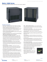
MKP 3000 Series
1
Chapter One
Introduction
About this Manual
About the MKP 3000 Series Remote Control Panels
iv
68-1069-01 C
04 07
All trademarks mentioned in this manual are the properties of their respective owners.

MKP 3000 Series • Introduction
MKP 3000 Series • Introduction
Introduction
1-3
Setup examples
The matrix switcher system can have up to 128 inputs and 128
outputs. However, for example, a conference room may have
three input devices and two output devices, a training room
next door may have four input devices and one output device,
and so on. Typically, each room has one or more MKP control
panels assigned to it, with each MKP limited to the inputs and
outputs that it can control.
In the example in figure 1-1, the “presentation room” (top,
center) has one output device, a projector (C), and four input
devices: a video camera (13), a laptop computer (12), and two
PCs (11 and 14). The “Media Room” (bottom, right) contains
the matrix switcher, as well as other inputs (1-6) and possibly
some control device(s).
Presentation
Room
Video Conference
Room
Training
Room
Media
Room
E
x
tr
o
n
E
le
c
tr
o
n
i
cs
MKP 3000
Keypad
C
O
M
P
A
Q
P
C
C
O
M
P
A
Q
P
C
C
O
M
P
A
Q
P
C
P
la
y
e
r
2
D
V
D
P
la
y
e
r
3
V
C
R
P
l
a
y
e
r
1
V
C
R
L
a
s
e
r
D
e
v
ic
e
C
o
n
t
r
o
ll
e
r
D
S
S
H
O
RIZ
O
N
TAL S
y
nc
VERTICA
L Sync
AU
D
IO
G
R
E
E
N
B
LU
E
R
E
D
A
C
Input
1-6
Input
7-9
Input
10
D
B
Input
11
Input
13
Input
14
12
I/O
SELECT
Extron
MKP 3000
Figure 1-1 — Typical MKP 3000 applications
An overflow crowd in the video conference room and/or the
training room may need to see a lecture going on in the
presentation room. In this case, the video camera (input 13)
must be available to those other rooms. Therefore, the MKPs in
the video conference and training rooms will be programmed to
allow selection of input 13 for displays in those rooms, in
addition to any video sources and/or displays there.
About this Manual
This manual provides installation and operation instructions for
the Extron MKP 3000, MKP 3000 L, and MKP 3000 MAAP
Remote Control Panels.
The MKP 3000 Series are network-ready remote control panels
that can control any Extron matrix switcher. The MKPs’ RS-232
ports allow them to communicate with other devices (another
MKP or a matrix switcher) locally and their Ethernet port allows
them to communicate with multiple devices.
The MKP 3000 L and the MKP 3000 MAAP are each functionally
the same device as the MKP 3000, but with the following
differences in their front panels:
• The MKP 3000 MAAP front panel includes a four-space
mini architectural adapter plate (MAAP) opening. Any
MAAP device can be installed in this space; but a typical
application would include an MKP 10 MAAP, which is an
auxiliary keypad for the MKP 3000.
• The MKP 3000 L model is designed to be installed in a
lectern. Its front panel is shorter and wider than that of
the MKP 3000, and has a built-in 12-button keypad similar
to the Extron MKP 10 MAAP. You can also install this
model in a rack, using the optional UCM RAAP controller
rack mounting kit.
In this manual, the term “MKP 3000” applies to all
three models unless the description specifically names a
particular model.
About the MKP 3000 Series Remote Control
Panels
You can create ties on the MKP 3000 in two modes: matrix mode
(the default) and input-only mode. In matrix mode, you specify
an input and one or more outputs to be tied to it. In input-only
mode, you select one output, then specify an input to be tied to
it. The MKP can also be dedicated to a specific group of inputs
and outputs when it is configured using the built-in Web pages.
You can also recall global presets, view current connections, or
adjust the volume for any output by using the front panel
controls, SIS
™
(Simple Instruction Set) commands, and/or the
embedded Web pages.
The MKP 3000 panel is mounted on a two-gang wall plate that
can be installed in a wall, conference table, podium, or other
convenient location. The MKP 3000 MAAP is mounted in a
three-gang wall plate, and the MKP 3000 L is mounted directly
onto a lectern or other furniture.
1-2

MKP 3000 Series • Introduction
Introduction
MKP 3000 Series
2
Chapter Two
Installation
MKP Installation Overview
Installation Procedures
Rear Panel and Side Panel Connections
Mounting the MKP 10 MAAP
1-4
RS-232 connection to the switcher
Any number of MKP 3000s can be connected to a matrix
switcher through its RS-232 port, but one MKP must be
designated as the primary controller. Other MKPs can be daisy
chained through the primary MKP remote control panel.
Ethernet connection to the switcher
Any number of MKP 3000s can be connected to a matrix
switcher as part of an Ethernet local area network (LAN).
Application diagram
Figure 1-2, below, shows an example of how multiple
MKP 3000s can be connected to a matrix switcher.
MKP 3000 MKP 3000
MKP 3000
X-Y Remote Control
Panel w/ LCD Display
M
K
P
3000
I
/
O
S
E
L
E
C
T
P
O
WE
R
R
E
S
E
T
M
KP
3
00
0
I
/
O
S
E
L
E
C
T
P
O
WE
R
R
E
S
E
T
M
KP
3
000
I/O
S
E
L
E
C
T
P
O
WE
R
R
E
S
E
T
Ethernet
Host
RS-232 Port
Switcher
RS-232 Port
Ethernet
Control
System
Matrix Switcher
Extron
MKP 3000 MAAP
X-Y Remote Control
Panel w/ LCD Display
and MAAP Openings
P
O
W
E
R
R
ESE
T
I/O
S
E
L
E
C
T
BACK
CA
N
C
EL
1
2
3
4
5
6
7
8
9
0
M
K
P
1
0
M
K
P
3
0
0
0
M
A
A
P
Extron
MKP 10 MAAP
Accessory 10-Key
Keypad
I
N
P
U
T
S
C
O
NT
RO
L
I/O
M
A
V
3
20
0
S
E
R
I
E
S
S
W
I
T
C
H
E
R
I
N
P
U
T
S
O
U
T
P
U
T
S
1
6
1
5
1
4
1
3
1
2
1
1
1
0
9
8
7
6
5
4
3
2
1
1
6
1
5
1
4
1
3
1
2
1
1
1
0
9
8
7
6
5
4
3
2
1
3
2
3
1
3
0
2
9
2
8
2
7
2
6
2
5
2
4
2
3
2
2
2
1
2
0
1
9
1
8
1
7
3
2
3
1
3
0
2
9
2
8
2
7
2
6
2
5
2
4
2
3
2
2
2
1
2
0
1
9
1
8
1
7
P
R
I
M
A
R
Y
R
E
D
U
N
D
A
N
T
P
O
W
E
R
S
U
P
P
L
Y
Figure 1-2 — MKP 3000 application diagram

MKP 3000 Series • Installation
MKP 3000 Series • Installation
Installation
2-3
3
Connect the cable between the MKP and the
matrix switcher. See “Rear Panel and Side Panel
Connections,” on page 2-10.
4
Connect power cords to the MKP and the matrix switcher.
5
Test the MKP’s ability to communicate with the matrix
switcher.
6
Disconnect power from all the devices.
7
Mount the MKP into the electrical box or to the mud ring.
If using a wall box, see “Mounting the MKP to a mounting
mud ring or wall box,” later in this chapter.
8
Restore power to the devices.
Installation Procedures
The MKPs can be mounted into a wall, furniture, or any other
convenient location. The MKP 3000 L can also be installed in a
rack, using the optional UCM RAAP Universal Controller Rack
Mounting Kit, part #70-344-02, -03). Follow the instructions
appropriate to the mounting option you have selected.
CAUTION
The control panel must be installed into a
Underwriters Laboratories (UL) approved electrical
wall box.
When installing MKP control panels, you must conform
to all national and local electrical codes.
Preparing the site
Choose a location that allows cable runs without interference.
Allow enough depth for both the wall box and the cables. You
may need to install the cables into the wall, furniture, or
conduits before installing the control panel.
The installation must conform to national and local electrical
codes and to the equipment’s size requirements. Cutout
templates that show the cut-out requirement for the circuitry
enclosure on the rear of the control panel are provided in
appendix A of this manual.
CAUTION
Only the MKP 3000 template in this manual is to
scale. Use the others for reference only.
CAUTION
Installation and service must be performed by
authorized personnel only. Extron recommends
that only UL listed electrical boxes be used. See
“UL Requirements for Wall Box Installation,” on
the next page.
The MKP 3000 remote control panel should be installed in a
standard, 2-gang electrical wall box (figure 2-1). The
MKP 3000 MAAP should be installed in a 3-gang wall box.
Figure 2-1 shows the MKP installed in a wall. This could also be in
a desk, a podium, or any other convenient location. The
MKP 3000 L can be installed in a lectern or in a rack using the
optional UCM RAAP controller rack mounting kit.
The procedures provided here assume that the electrical wall
boxes and the cables have been installed for the system. “Rear
Panel and Side Panel Connections,” starting on page 2-10,
provides guidance for terminating the cables.
Extron
MKP 3000
I/ O
SELECT
POWER
RESET
Figure 2-1 — MKP mounted in a wall box
MKP Installation Overview
To install an MKP 3000 remote control panel, follow these steps:
1
Disconnect power from the matrix switcher and all MKPs
in the system.
2
Prepare the site: cut a hole in the wall or furniture, install
the electrical box or mounting bracket (“mud ring”) if
needed, and prepare the cables. Instructions are included
in this manual and/or with the wall box. See “Installation
Procedures,” on the next page.
2-2

MKP 3000 Series • Installation
MKP 3000 Series • Installation
Installation, cont’d
4. Check the opening size by inserting the wall box, mud
ring, or control panel into the opening. The box or mud
ring and/or control panel should fit easily into the
opening. Enlarge or smooth the edges of the opening if
needed.
5. If you are using a wall box, feed the cables through the
wall box punch-out holes, and secure them with cable
clamps to provide strain relief.
6. Exposed cable shields (braids or foil) are potential sources
of short circuits. Trim back and/or insulate shields with
heat shrink (figure 2-2).
Installation
Cable
Cable
Clamp
Wall Stud
Foil
Shield
Screws or Nails
Screw
Braided
Shield
Figure 2-2 — Grounding braided and foil shields
To prevent short circuits, the outer foil shield can be
cut back to the point where the cable exits the cable
clamp. Both braided and foil shields should be
connected to an equipment ground at the other end
of the cable.
7. If you are using a mud ring, follow the directions, if any,
that came with the mud ring to attach the clips that fasten
it to the wall or furniture (figure 2-3).
To meet UL listing requirements, the MKP must be
installed in a wall box.
2-5
UL requirements for wall box installation
The following UL requirements pertain to the installation of the
MKP 3000 into a wall (figure 2-1) or furniture.
1. These units are not to be connected to a centralized DC
power source or used beyond their rated voltage range.
2. These units must be installed in UL listed junction boxes.
3. These units must be installed with conduit in accordance
with the National Electrical Code.
Installing a mounting bracket (mud ring) or wall
box
Extron recommends using a UL listed wall box (available from
Extron) for most mounting options, but you can use the
included mounting brackets (mud rings) instead.
Before using the mud rings, verify that the installation
conforms to national and local electrical codes.
The electrical box must be at least 2.5" (7 cm) deep to
accommodate the MKP’s rear enclosure.
Install the mud ring or wall box as follows:
1. If you are using a mud ring, use the template that came
with the mud ring. Cut out the indicated center portion.
To meet the UL listing requirements, the MKP must be
installed in a wall box.
If you are using a wall box, refer to the cut-out template
in appendix A that corresponds to the faceplate you are
using, and cut out the center portion of it as indicated on
the template.
CAUTION
Extron provides one mud ring with each MKP
control panel. However, the user may choose to use
a wall box. Because the tolerances on electrical
boxes are very loose, Extron recommends that you
measure the actual box that you plan to use before
making any precise cuts.
2. Use the template (or place the wall box or mud ring
against the installation surface), and mark the guidelines
for the opening on the wall or furniture.
3. Cut out the wall material from the marked area.
2-4

MKP 3000 Series • Installation
MKP 3000 Series • Installation
Installation, cont’d
Flush with
Wall Surface
Screws or Nails
Wall Stud
Wall Box
Figure 2-4 — Attaching a wall box to a wall stud
8. Connect the Ethernet and/or RS-232 cable (as appropriate)
and the power cable, and test the MKP before fastening the
MKP into the wall box. See “Rear Panel and Side Panel
Connections,” on page 2-10, for details.
The rear panel connectors are inaccessible after
installation.
Mounting the MKP to a mud ring or wall box
If the installation involves an MKP 3000 MAAP and an
optional MKP 10 MAAP remote keypad, mount the
MKP 10 MAAP to the MKP 3000 MAAP before
installing the MKP 3000 MAAP into the mud ring or
wall box. See “Mounting the MKP 10 MAAP,” on
page 2-19.
1. Remove power from the control panel by disconnecting
the power supply.
2. Place the control panel through the opening in the wall or
furniture and through the mud ring or into the wall box.
Take care not to damage the cables, which fit behind the
MKP, at the back of the wall box.
2-72-6
E
xtron
M
K
P
3
0
0
0
I
/
O
S
E
L
E
C
T
P
O
WER
R
ES
E
T
Detail A
0.75" #6-32 Screw
Backing Clip
Backing Clip
Sheet Rock
Sheet Rock
Mounting Bracket
Mounting Bracket
Detail B
1.25" #6-32 Screw
Backing clip can
be in either orientation.
See Detail A or Detail B.
Extron
MKP 3000
Figure 2-3 — Attaching a mud ring to a wall
If you are using a wall box, insert the wall box into the
opening, and attach it to the wall stud or furniture with
nails or screws, leaving the front edge flush with the outer
wall or furniture surface (figure 2-4).
If attaching the wall box to wood, use four #8 or #10
screws or 10-penny nails. A minimum of ½ inch (1.3 cm)
of screw threads must penetrate the wood.
If attaching the wall box to metal studs or furniture, use
four #8 or #10 self-tapping sheet metal screws or machine
bolts with matching nuts.

MKP 3000 Series • Installation
MKP 3000 Series • Installation
Installation, cont’d
2. Cable the MKP and any AAPs within the UCM panel (see
“Rear Panel and Side Panel Connections,” later in this
chapter).
3. Align the UCM panel in the rack, and secure it using the
remaining screws.
E
x
tr
o
n
P
O
W
E
R
R
E
S
E
T
I
/
O
SELEC
T
BACK
CANCEL
1
2
3
4
5
6
7
8
9
0
V
ID
E
O
G
R
E
E
N
A
U
D
IO
R
E
D
T
A
K
EO
U
T
P
U
T
IN
PU
T
M
K
P
3
0
0
0
L
Extron
MKP 3000 L
Extron
UCM-RAAP
Figure 2-6 — Mounting the MKP 3000 L to the
UCM RAAP and a rack
UL requirements for rack mounting
The following Underwriters Laboratories (UL) requirements
pertain to the installation of the MKP 3000 L into a rack.
1. Elevated operating ambient temperature — If the
equipment is installed in a closed or multiunit rack
assembly, the operating ambient temperature of the rack
environment may be greater than room ambient.
Therefore, consider installing the equipment in an
environment compatible with the maximum ambient
temperature (Tma) specified by the manufacturer. For the
MKP 3000, the Tma is 122 °F (50 °C).
2. Reduced air flow — Installation of the equipment in a
rack should be such that the amount of air flow required
for safe operation of the equipment is not compromised.
2-9
3. Mount the MKP’s faceplate to the mud ring or wall box
with machine screws (figure 2-5).
E
xtron
M
K
P
300
0
I
/
O
S
E
L
E
C
T
P
O
W
E
R
R
E
S
E
T
Figure 2-5 — Mounting the MKP to the wall box
4. Reconnect the power supply and restore power.
Mounting the MKP 3000 L
You can mount the MKP 3000 L in a lectern or other furniture, or
you can mount it in a rack using the UCM RAAP controller
mounting kit.
Mounting the MKP 3000 L in a lectern
To mount the MKP 3000 L in a lectern or other furniture,
1. Using the MKP 3000 L cut-out template in appendix A,
measure and mark guidelines for the opening in the
furniture.
2. Cut out the furniture material from the marked area.
3. Check the opening size by inserting the MKP into it.
Enlarge and/or smooth the edges of the opening as
needed.
4. Complete all necessary cabling, and, with power
disconnected at the source, insert the MKP into the
opening.
5. Fasten the MKP directly to the furniture using four #8 or
#10 screws or 10-penny nails.
Mounting the MKP 3000 L in a rack
To mount the MKP 3000 L in a rack using the UCM RAAP,
1. Attach the MKP 3000 L to the UCM RAAP using the four
flat Philips head machine screws provided with the UCM.
2-8

MKP 3000 Series • Installation
MKP 3000 Series • Installation
Installation, cont’d
3
1
2
4
5
6
Figure 2-8 — MKP 3000 MAAP rear panel
3
1
2
4
5
7
Figure 2-9 — MKP 3000 L rear panel
1
LAN (Ethernet) port — If desired, connect a
Category (CAT) 5e or higher (network) cable
between this connector and either the matrix
switcher to be controlled or to an Ethernet
local area network (LAN). See “Ethernet cable
termination,” later in this chapter, to properly
wire the RJ-45 connector for your application.
Ethernet connection indicators — The Link and Activity LEDs
on the LAN port indicate the status of the Ethernet connection.
The green Link LED indicates that the MKP is properly
connected to an Ethernet LAN. This LED should light steadily.
The yellow Activity LED indicates transmission of data packets
on the RJ-45 connector. This LED should flicker as the MKP
communicates.
2
Power connector — Connect the included external 12 VDC
power supply to this 2-pole direct insertion connector. See
“Power supply wiring,” on page 2-18, to wire the connector.
2-11
3. Mechanical loading — Mounting of the equipment in the
rack should be such that a hazardous condition is not
achieved due to uneven mechanical loading.
4. Circuit overloading — Consideration should be given to
the connection of the equipment to the supply circuit and
the effect that overloading of the circuits might have on
overcurrent protection and supply wiring. Appropriate
consideration of equipment nameplate ratings should be
used when addressing this concern.
5. Reliable earthing (grounding) — Reliable earthing of
rack-mounted equipment should be maintained.
Particular attention should be given to supply connections
other than direct connections to the branch circuit (for
example, use of power strips).
Rear Panel and Side Panel Connections
All connectors are on the rear or side of the MKP (figure 2-7, 2-8,
and 2-9). These connectors are inaccessible once the MKP is
installed.
GND
12 V
REMOTE
KEYPAD
POWER
.5A MAX
Tx
HOST
RS-232
SWITCH
RS-232
Rx
GND
Tx
Rx
GND
G
N
D
12 V
REMOTE
KEYPAD
POW
ER
.5A MAX
Tx
HOST
RS-232
SWITCH
RS-232
Rx
G
N
D
Tx
Rx
G
N
D
3
1
2
4
5
Figure 2-7 — MKP 3000 rear and side panels
2-10
RJ-45
Port
Link
LED
Activity
LED

MKP 3000 Series • Installation
MKP 3000 Series • Installation
Installation, cont’d
2-13
Control connections
The MKP has two RS-232 ports (a Host port [
4
] and a Switch
port [
5
]) and an LAN (Ethernet) port (
1
). The following
paragraphs describe different possible ways of connecting the
MKP to a switcher via RS-232 or Ethernet.
RS-232 connection
An MKP control panel can be directly cross-connected to any
Extron matrix switcher through the switcher’s switch RS-232
port (see figure 2-16, later in this chapter, for pin assignments
for the RS-232 cable). A control system or host computer can be
connected via the MKP’s Host RS-232 port.
Additional MKPs can be connected to the matrix switcher
through the MKP that is RS-232 connected (the primary MKP).
In the configuration shown in figure 2-11, additional
(secondary) MKPs are connected to the primary MKP via the
primary MKP’s Ethernet port.
Ethernet
MKP 3000
MKP 3000
MKP 3000
MKP 3000
MKP 3000
Host
RS-232 Port
Switcher
RS-232 Port
Ethernet
Control
System
Matrix Switcher
I
N
P
U
T
S
CONTROL
O
U
T
P
U
T
S
I/O
1 2 3 4 5 6 7 8 9 10 11 12
13 14 15 16 17 18 19 20 21 22 23 24
1 2 3 4 5 6 7 8 9 10 11 12
13 14 15 16 17 18 19 20 21 22 23 24
MAV 2400 SERIES SWITCHER
MKP 3000
VOLUME
I/O
I/O
SELECT
Extron
MKP 3000
I/O
SELECT
Extron
MKP 3000
I/O
SELECT
Extron
MKP 3000
I/O
SELECT
Extron
MKP 3000
Figure 2-11 — MKP connection using the RS-232 port
3
Remote Keypad port — If desired, plug the optional
MKP 10 MAAP remote keypad into this 10-pin connector, using
the cable included with the MKP 10 MAAP.
This connector is always used on the standard keypad on
an MKP 3000 L.
4
Host RS-232 port — If desired, connect a host computer or
control system to this 3-pole, 3.5 mm, RS-232 connector
(figure 2-10).
Pin Function
TX
RX
Gnd
Transmit data
Receive data
Signal ground
Tx
HOST
RS-232
SWITCH
RS-232
Rx
GND
Tx
Rx
GND
Figure 2-10 — RS-232 connector
5
Switch RS-232 port — If desired, connect a cable between this
3-pole, 3.5 mm, RS-232 connector and a matrix switcher
(figure 2-10).
6
MAAP Opening (MKP 3000 MAAP) — The MKP 3000 MAAP
has a space that allows the installation of up to four optional
mini architectural adapter plates (MAAPs). This space is
typically filled by an optional four space MKP 10 MAAP
keypad, but a variety of other adapter plates are also available.
Blank plates (two single-space and one double-space plate) are
included with the MKP to cover unused spaces. The
MKP 10 MAAP or other MAAP(s) must be ordered separately.
They also should be attached to the faceplate and cabled before
the MKP is installed in the wall or furniture. See “Mounting the
MKP 10 MAAP,” later in this chapter.
7
Keypad board (MKP 3000 L) — The 12-button keypad that is
built into the MKP 3000 L rear panel is connected to this board.
2-12

MKP 3000 Series • Installation
MKP 3000 Series • Installation
Installation, cont’d
Wire the connectors as follows:
The total cable length between an MKP control panel
and a matrix switcher should not exceed 100 feet (30 m).
1. Choose a cable such as Extron’s Comm-Link cable. The
wire specifications for Comm-Link cable are in
appendix A, “Reference Information.” Colors may vary
from this example.
2. Trim approximately 1.5" (3.8 cm) of the cable jacket to
expose the four insulated wires and a bare drain wire
(silver-colored).
3. Cut off the foil shield and discard it.
4. Strip ¼" ( 0.6 cm) of insulation from three of the four wires.
5. Twist the strands of each wire, insert them into the direct
insertion connector, and tighten the captive screws.
Ethernet connection
An MKP control panel can be directly connected to any
Ethernet-enabled matrix switcher via the switcher’s Ethernet
port (figure 2-13) using a TP (network) cable that is wired as a
crossover cable (see “TP cable termination,” later in this chapter,
to properly wire the cable).
MKP 3000
Crossover
Cable
LAN Port
Matrix Switcher
I
N
P
U
T
S
CONTROL
O
U
T
P
U
T
S
I/O
1 2 3 4 5 6 7 8 9 10 11 12
13 14 15 16 17 18 19 20 21 22 23 24
1 2 3 4 5 6 7 8 9 10 11 12
13 14 15 16 17 18 19 20 21 22 23 24
MAV 2400 SERIES SWITCHER
I/O
SELECT
Extron
MKP 3000
Figure 2-14 — Direct MKP connection using the
LAN port
Any number of control panels can be connected as part of a
network to any Ethernet-enabled matrix switcher via the
switcher’s Ethernet port (figure 2-14). All TP cables in this
example are wired as patch (straight-through) cables.
2-152-14
Multiple primary MKPs can also be daisy-chained together,
with the first MKP connected to the switcher’s RS-232 port and
the others connected to each other via their own RS-232 ports.
Figure 2-12 shows an example of this type of configuration.
MKP 3000
Primary/Pass-
through
MKP 3000 L
Primary/MKP 3000
Host
RS-232 Port
Switcher
RS-232 Port
Tx
Tx
Tx
Tx
Rx
Rx
Rx
Rx
Switcher
RS-232 Port
Matrix Switcher
I
N
P
U
T
S
C
O
N
T
R
O
L
I
/
O
M
A
V
3
2
0
0
S
E
R
I
E
S
S
W
I
TC
H
ER
I
N
P
U
T
S
O
U
T
P
U
T
S
1
6
1
5
1
4
1
3
1
2
1
1
1
0
9
8
7
6
5
4
3
2
1
1
6
1
5
1
4
1
3
1
2
1
1
1
0
9
8
7
6
5
4
3
2
1
3
2
3
1
3
0
2
9
2
8
2
7
2
6
2
5
2
4
2
3
2
2
2
1
2
0
1
9
1
8
1
7
3
2
3
1
3
0
2
9
2
8
2
7
2
6
2
5
2
4
2
3
2
2
2
1
2
0
1
9
1
8
1
7
P
R
I
M
A
R
Y
R
E
D
U
N
D
A
N
T
P
O
W
E
R
S
U
P
P
L
Y
P
O
W
E
R
R
E
S
E
T
I
/
O
S
E
L
E
C
T
B
A
C
K
C
A
N
C
E
L
1
2
3
4
5
6
7
8
9
0
M
K
P
1
0
Extr
on
M
K
P
3
00
0
M
A
A
P
Extron
P
O
W
E
R
R
E
S
E
T
I
/O
S
ELECT
B
A
C
K
C
A
N
C
E
L
1
2
3
4
5
6
7
8
9
0
V
I
D
E
O
GRE
E
N
A
U
D
I
O
R
E
D
T
A
K
E
O
U
T
P
U
T
I
N
P
U
T
M
K
P
3
0
0
0
L
Figure 2-12 — Daisy-chaining MKP 3000s
RS-232 cable termination
Each MKP control panel has two RS-232 ports that are
connected using 3.5 mm, 3-pole direct insertion connectors.
Figure 2-13 shows the pin assignments for these ports.
Pin Switcher RS-232 MKP RS-232
1 – –
2 Tx Rx
3 Rx Tx
4 – –
5 Gnd Gnd
6 – –
7 – –
8 – –
9 – –
Figure 2-13 — RS-232 cross-connection table

MKP 3000 Series • Installation
MKP 3000 Series • Installation
Installation, cont’d
• Crossover cable — Direct connection between the MKP
and a host computer or an Ethernet-enabled matrix
switcher (figure 2-14)
• Patch (straight) cable — Network connection between
the MKP and an Ethernet LAN (figure 2-14)
For pin assignments, see figure 2-16, below.
Patch (straight) cable
Side 1 Side 2
Pin Wire color Pin Wire color
1 White-orange 1 White-orange
2 Orange 2 Orange
3 White-green 3 White-green
4 Blue 4 Blue
5 White-blue 5 White-blue
6 Green 6 Green
7 White-brown 7 White-brown
8 Brown 8 Brown
Crossover cable
Side 1 Side 2
Pin Wire color Pin Wire color
1 White-orange 1 White-green
2 Orange 2 Green
3 White-green 3 White-orange
4 Blue 4 Blue
5 White-blue 5 White-blue
6 Green 6 Orange
7 White-brown 7 White-brown
8 Brown 8 Brown
Clip Down
Side
1
1&2
3&6
4&5
7&8
2345678
Pins
12345678
RJ-45
connector
Twisted
Pairs
Figure 2-16 — RJ-45 connector and pinout tables
2-172-16
Ethernet
MKP 3000
MKP 3000
MKP 3000
MKP 3000
RS-232
Control
System
Matrix Switcher
I
N
P
U
T
S
CONTROL
O
U
T
P
U
T
S
I/O
1 2 3 4 5 6 7 8 9 10 11 12
13 14 15 16 17 18 19 20 21 22 23 24
1 2 3 4 5 6 7 8 9 10 11 12
13 14 15 16 17 18 19 20 21 22 23 24
MAV 2400 SERIES SWITCHER
I/O
SELECT
Extron
MKP 3000
I/O
SELECT
Extron
MKP 3000
I/O
SELECT
Extron
MKP 3000
I/O
SELECT
Extron
MKP 3000
Figure 2-15 — Network MKP connection using the
LAN port
Ethernet (TP) cable termination
It is vital that you use the correct Ethernet cables, and that they
be properly terminated with the correct pinout. Ethernet links
use Category (CAT) 5, 5e or CAT 6, unshielded twisted pair
(UTP) or shielded twisted pair (STP) cables, terminated with
RJ-45 connectors. Ethernet cables are limited to 328' (100 m).
CAUTION
Do not use standard telephone cables. Telephone
cables do not support Ethernet or Fast Ethernet.
Do not stretch or bend cables. This can cause
transmission errors.
The cable you use depends on your network speed. The MKP
supports both 10 Mbps (10Base-T — Ethernet) and 100 Mbps
(100Base-T — Fast Ethernet), half-duplex and full-duplex,
Ethernet connections.
• 10Base-T Ethernet requires CAT 5 UTP or STP cable as a
minimum
• 100Base-T Fast Ethernet requires CAT 5e UTP or STP
cable as a minimum
The Ethernet cable can be terminated as a straight-through cable
or a crossover cable. It must be terminated properly for your
application (figure 2-16).

MKP 3000 Series • Installation
MKP 3000 Series • Installation
Installation, cont’d
2-18
Power supply wiring
Figure 2-17 shows how to wire the power connector.
Power Supply
Output Cord
Direct Insertion
Connector
SECTION A–A
Ridges
Smooth
A A
12 V
GND
Figure 2-17 — Power connector wiring
CAUTION
Power supply voltage polarity is critical. Incorrect
voltage polarity can damage the power supply and
the MKP. Identify the power cord negative lead by
the ridges on the side of the cord (see figure 2-17,
above).
To verify the polarity before connection, plug in the power
supply with no load and check the output with a voltmeter.
The length of the exposed (stripped) copper wires is
important. The ideal length is 3/16" (5 mm). Longer
bare wires can short together. Shorter wires are not as
secure in the direct insertion connectors and could be
pulled out.
Do not tin the power supply leads before installing them
in the direct insertion connector. Tinned wires are not as
secure in the connectors and could be pulled out.
The two power cord wires must be kept separate
while the power supply is plugged in. Remove
power before wiring.
Alternatively, you can use the optional Extron P/S 123
Universal 12 VDC Power Supply, part #60-814-01, which can
power up to 10 Extron 12 VDC devices using only one AC
power connector.
Mounting the MKP 10 MAAP
The MKP 3000 MAAP has a space that allows the installation of
up to four optional mini architectural adapter plates. This space
is typically filled by an optional four space MKP 10 MAAP
keypad (figure 2-18).
BACK
CANCEL
1 2 3
4 5 6
7 8 9
0
MKP 10
Figure 2-18 — MKP 10 MAAP keypad
When the connected switcher has a large matrix size (up to 128
by 128) selecting an input or output number by rotating the
Select knob can be inconvenient. The optional MKP 10 MAAP
keypad allows rapid input/output selection.
Mount the MKP 10 MAAP to the MKP 3000 MAAP before
installing the MKP 3000 MAAP, as follows:
The proper MKP 10 MAAP orientation is with the
power LED up.
2-19

MKP 3000 Series • Installation
MKP 3000 Series • Installation
Installation, cont’d
1. Sandwich the MKP 3000 MAAP panel between the
MKP 10 MAAP module (without its front panel) and the
MKP 10 MAAP’s front panel. Secure the front panel to the
module with the included #4-40 screws (see figure 2-19 ).
P
O
W
E
R
R
E
S
E
T
I/
O
S
E
L
E
C
T
Ext
ron
M
KP 30
00 M
AA
P
BA
CK
CAN
CEL
1
2
3
4
5
6
7
8
9
0
M
K
P
1
0
(4) #4-40
Screws
Extron
MKP 10
Module
Extron
MKP 3000 MAAP
Panel
Extron
MKP 10
Front Panel
Figure 2-19 — Mounting the MKP 10 MAAP
2-20
2. See figure 2-20. If you have not already done so, connect
the serial control and power cables between the J1
connector (
1
) on the MKP 10 MAAP and the Remote
Keypad port (
2
) on the rear of the MKP 3000 MAAP.
2
1
Figure 2-20 — MKP 3000 MAAP rear panel with
MKP 10 MAAP mounted
1
MKP 10 MAAP J1 control connector
2
MKP 3000 MAAP Remote Keypad port
3. Mount the MKP 3000 MAAP (with the mounted
MKP 10 MAAP) to the wall box or mounting bracket. See
“Mounting the MKP to mud ring or wall box,” earlier in
this chapter.
2-21

MKP 3000 Series • Installation
Installation, cont’d
MKP 3000 Series
3
Chapter Three
Local Operation
Front Panel Controls and Indications
Front Panel Operations
Rear Panel Resets
MKP 10 MAAP and MKP 3000 L Keypad Operation
2-22
/