Page is loading ...

Multichannel Media Converter
33214.A
METTF10xx, MFETF10xx

COMPLIANCE INFORMATION
UL Listed
C-UL Listed (Canada)
CISPR/EN55022 Class A
FCC Regulations
This equipment has been tested and found to comply with the limits for a class A digital device, pursuant to part 15 of
the FCC rules. These limits are designed to provide reasonable protection against harmful interference when the
equipment is operated in a commercial environment. This equipment generates, uses, and can radiate radio frequency
energy and, if not installed and used in accordance with the instruction manual, may cause harmful interference to
radio communications. Operation of this equipment in a residential area is likely to cause harmful interference, in
which case the user will be required to correct the interference at the user’s own expense.
Canadian Regulations
This digital apparatus does not exceed the Class A limits for radio noise for digital apparatus set out on the radio
interference regulations of the Canadian Department of Communications.
Le présent appareil numérique n'émet pas de bruits radioélectriques dépassant les limites applicables aux appareils
numériques de la class A prescrites dans le Règlement sur le brouillage radioélectrique édicté par le ministère des
Communications du Canada.
European Regulations
Warning
This is a Class A product. In a domestic environment this product may cause radio interference in which case the user
may be required to take adequate measures.
Achtung !
Dieses ist ein Gerät der Funkstörgrenzwertklasse A. In Wohnbereichen können bei Betrieb dieses Gerätes
Rundfunkstörungen auftreten, in weichen Fällen der Benutzer für entsprechende Gegenmaßnahmen werantwortlich ist.
Attention !
Ceci est un produit de Classe A. Dans un environment domestique, ce produit risque de créer des interférences
radioélectriques, il appartiendra alors à l’utilsateur de prende les measures spécifiques appropriées
VCCI Class 1 Compliance
This equipment is in the 1st Class category
(information equipment to be used in commercial
and/or industrial areas) and conforms to the standards
set by the Voluntary Control Council For Interference
by Data Processing Equipment and Electronic Office
Machines aimed at preventing radio interference in
commercial and/or industrial areas. When used in a
residential area or in an adjacent area thereto,
interference may be caused to radio and TV
receivers, etc. Read the instructions for correct
handling.
Trademark Notice
All registered trademarks and trademarks are the property of their respective owners.
Copyright Restrictions
© 2001 TRANSITION Networks.
All rights reserved. No part of this work may be reproduced or used in any form or by any means – graphic, electronic,
or mechanical – without written permission from TRANSITION Networks.
Printed in the U.S.A.
CAUTION: RJ CONNECTORS ARE NOT INTENDED FOR CONNECTION TO THE PUBLIC
TELEPHONE NETWORK. Failure to observe this caution could result in damage to the public telephone
network.
Der Anschluss dieses Gerätes an ein öffentlickes Telekommunikationsnetz in den EG-Mitgliedstaaten
verstösst gegen die jeweligen einzelstaatlichen Gesetze zur Anwendung der Richtlinie 91/263/EWG zur
Angleichung der Rechtsvorschriften der Mitgliedstaaten über Telekommunikationsendeinrichtungen einschliesslich
der gegenseitigen Anerkennung ihrer Konformität.

Table of Contents
1. INTRODUCTION . . . . . . . . . . . . . . . . . . . . . . . . . . . . . . . . .1.1
1.1 Multichannel Media Converter Models . . . . . . . . . . . . 1.2
1.2 Media Converter Channels . . . . . . . . . . . . . . . . . . . . . 1.2
1.3 Channel Switches . . . . . . . . . . . . . . . . . . . . . . . . . . . . 1.3
1.4 Reset Button . . . . . . . . . . . . . . . . . . . . . . . . . . . . . . . . 1.3
1.5 AC Power Supply Module/Optional Redundant AC Power
Supply Module . . . . . . . . . . . . . . . . . . . . . . . . . . . . . . 1.3
1.6 Multichannel Media Converter Management Module . 1.4
1.7 Multiport Management Software at Remote NMS . . . . 1.5
2. INSTALLATION . . . . . . . . . . . . . . . . . . . . . . . . . . . . . . . . . . .2.1
2.1 Preparing the Site . . . . . . . . . . . . . . . . . . . . . . . . . . . . . 2.2
2.2 Unpacking METTF10xx, MFETF10xx Equipment . . . . . 2.3
2.3 Installing Optional Redundant Power Supply Module . 2.4
2.3.1 Setting Management Module Jumper .2.4
2.3.2 Installing Power Supply Module . . . . .2.5
2.4 Installing Multichannel Media Converter at Site . . . . . . 2.6
2.4.1 Standard Rack Installation . . . . . . . . .2.6
2.4.2 Table-Top Installation . . . . . . . . . . . . .2.7
2.5 Powering the Multichannel Media Converter . . . . . . . 2.8
2.6 Connecting Channel Ports to Network . . . . . . . . . . . . . 2.9
2.6.1 Setting FDX/HDX Channel Configuration
Switches . . . . . . . . . . . . . . . . . . . . . . . . . . .2.9
2.6.2 Installing Fiber-optic Cable . . . . . . . .2.10
2.6.3 Installing Twisted-Pair Copper Cable 2.11
2.7 Setting Network Management Parameters . . . . . . . . . 2.12
2.8 Connecting to TCP/IP Network Management at Remote
Network Management Station (NMS) . . . . . . . . . . . . . 2.14
2.9 Installing Multiport Management Software at Remote NMS .
. . . . . . . . . . . . . . . . . . . . . . . . . . . . . . . . . . . . . . . . . . 2.15
MULTICHANNEL MEDIA CONVERTER
i

3. OPERATION . . . . . . . . . . . . . . . . . . . . . . . . . . . . . . . . . . . . .3.1
3.1 Using Status LEDs . . . . . . . . . . . . . . . . . . . . . . . . . . . . 3.2
3.2 Using a Terminal Emulator . . . . . . . . . . . . . . . . . . . . . 3.3
3.3 Using Multiport Management Software at Remote NMS 3.6
4 MAINTENANCE . . . . . . . . . . . . . . . . . . . . . . . . . . . . . . . . . .4.1
4.1 Fault Isolation and Recovery . . . . . . . . . . . . . . . . . . . . 4.2
4.2 Hardware Replacement Procedures . . . . . . . . . . . . . . . 4.5
4.2.1 Replacing Management Module . . . . .4.5
4.2.2 Replacing AC Power Supply Module .4.6
APPENDIX . . . . . . . . . . . . . . . . . . . . . . . . . . . . . . . . . . . . . . . . .A.1
Appendix A. Technical Specifications . . . . . . . . . . . . . . . . . . A.1
Appendix B. Cable Specifications . . . . . . . . . . . . . . . . . . . . . B.1
METTF10xx, MFETF10xx
ii

1. INTRODUCTION
The TRANSITION Networks METTF10xx (Ethernet
™
) and MFETF10xx (Fast
Ethernet
™
) series Multichannel Media Converters connect twisted-pair
copper cable to fiber-optic cable in separate copper-to-fiber media
converter pairs, called channels. The network administrator can select a
Multichannel Media Converter that provides up to six (6) or up to twelve
(12) channels, with either 10BASE-T/10BASE-FL or 100BASE-TX
/100BASE-FX connections and with either ST or SC fiber connectors.
The Multichannel Media Converter can be installed as a standalone unit
or in a standard rack and can be managed at an attached terminal or using
an SNMP application at a remote Network Management Station. Full-
duplex or half-duplex network operation, for each channel, is switch-
selectable or software-selectable.
1.1 Multichannel Media Converter Models .................................1.2
1.2 Media Converter Channels ....................................................1.2
1.3 Channel Switches ..................................................................1.3
1.4 AC Power Supply Module/Optional Redundant AC Power
Supply Module .......................................................................1.3
1.5 Multichannel Media Converter Management Module ...........1.4
1.6 Multiport Management Software at Remote NMS .................1.5
1.1
MULTICHANNEL MEDIA CONVERTER

1.1 Multichannel Media Converter Models
The TRANSITION Networks METTF10xx and MFETF10xx series
Multichannel Media Converters can be selected according to network
requirements:
MFETF1011-120 12-channel 100 Mb/s, multimode fiber, ST
connectors
MFETF1013-120 12-channel 100 Mb/s, multimode fiber, SC
connectors
MFETF1011-060 6-channel 100 Mb/s, multimode fiber, ST
connectors
MFETF1013-060 6-channel 100 Mb/s, multimode fiber, SC
connectors
METTF1011-120 12-channel 10 Mb/s, multimode fiber, ST
connectors
METTF1013-120 12-channel 10 Mb/s, multimode fiber, SC
connectors
METTF1011-060 6-channel 10 Mb/s, multimode fiber, ST
connectors
METTF1013-060 6-channel 10 Mb/s, multimode fiber, SC
connectors
1.2 Media Converter Channels
Channels connect twisted-pair copper cable to fiber-optic cable.
Twisted-Pair Ports IEEE802.3-compliant 10BASE-T/100BASE-TX twisted-
pair ports operate at 10Mb/s or 100Mb/s, full-duplex or half-duplex.
Fiber-Optic Ports IEEE802.3-compliant 10BASE-FL/100BASE-FX fiber-
optic ports operate at 10Mb/s or 100Mb/s, full-duplex or half-duplex.
Channel LEDs A set of LEDs monitor the status
of EACH Media Converter channel.
T-LNK Steady LED indicates that twisted-
pair link has been established
between the channel and the
twisted-pair node
F-LNK Steady LED indicates that fiber link
has been established between the
channel and the fiber node
ACTIVE Steady LED indicates that fiber port is receiving traffic.
1.2
METTF10xx, MFETF10xx
7
Tx
1
Tx
T-LNK
F-LNK
ACTIVE
7
Rx
Tx
8
Rx
Tx
9
Rx
Tx
10
Rx
Tx
11
Rx
Tx
12
Rx
Tx
1
Rx
Tx
2
Rx
Tx
3
Rx
Tx
4
Rx
Tx
5
Rx
Tx
6
Rx
Tx
POWER
MAIN
BCKP
TEST
REC
LNK
Ready
RESET
MANAGEMENT
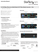
Managed Fast Ethernet 100BASE-TX to 100BASE-FX
T-LNK
F-LNK
ACTIVE
1 2 3 4
5 6 7
1 2 3 4
5 6
TEST
HDX
NORM
FDX
1 2 3 4
5 6 7
1 2 3 4
5 6
TEST
HDX
NORM
FDX
X
II

1.3 Channel Switches
Full-duplex/half-duplex mode selection
switches (DIP switches #1-6) allow the
network administrator to set EACH media
converter channel, separately, either to full-
duplex or to half-duplex.
The Link Test switch (DIP switch #7)
enables or disables the Missing Link Test
feature for a block of six (6) Multichannel
Media Converter channels.
1.4 Reset Button
Located only on 100BASE-TX MFETF10xx series Multichannel Media
Converter models, the Rest button, if present, allows the network
administrator to reset ALL Multichannel Media Converter channel ports.
1.5 AC Power Supply Module/Optional Redundant
AC Power Supply Module
An AC Power Supply Module, installed at the back of the Multichannel
Media Converter before shipment, supplies power to the Multichannel
Media Converter through an external power cord connected to an external
AC outlet.
NOTE: The Multichannel Media Converter does not have an ON/OFF
power switch. Power is applied to, and removed from, the Multichannel
Media Converter by connecting and disconnecting the power cord.
The Multichannel Media Converter rear panel also contains an expansion
slot for an optional redundant Power Supply Module. When installed, the
optional redundant Power Supply Module shares the power load with the
main AC Power Supply Module. If one power supply fails, the remaining
power supply assumes the role of providing all power to the Multichannel
Media Converter, thereby protecting the Multichannel Media Converter
from a system failure.
NOTE: Both the redundant Power Supply Module and the main AC Power
Supply Module can be "hot swapped".
The MAIN power LED on the front panel of the
Multichannel Media ConverterLED is a steady amber
when thef the AC Power Supply Module is operating
properly. When the optional redundant Power Supply
Module is installed and operating properly, the BCKP
power LED is a steady green.
1 INTRODUCTION
1.3
MULTICHANNEL MEDIA CONVERTER
1 2 3 4
5 6 7
1 2 3 4
5 6
TEST
HDX
NORM
FDX
POWER
MAIN
BCKP
TEST
M
ENT
100BASE-TX to 100BASE-FX

1.6 Multichannel Media Converter Management
Module
TRANSITION Networks Multichannel Media Converters are shipped with
a Management Module installed and functional. Embedded SNMP
software in the Management Module allows network management of the
Multichannel Media Converter.
Connections to Management Module
The network administrator can manage the Multichannel Media Converter
using Management Module SNMP software accessed either through the
PS/2 serial port or through the RJ-45 network port.
Management Module LEDs
A set of LEDs monitor the status of the Management Module.
LNK Steady LED indicates that a link has been
established to the Management Module
through the PS/2 serial port or through the
RJ-45 network port.
REC Steady LED indicates that the Management
Module is receiving traffic through the PS/2
serial port or through the RJ-45 network
port.
Ready Steady LED indicates that the Management
Module is properly installed and receiving power.
Serial Port
The network administrator can manage the Multichannel Media Converter
through a command-line interface at a terminal or terminal emulator
conected to the PS/2 port, through the supplied cable (PS/2 to DB9).
1.4
METTF10xx, MFETF10xx
Attached terminal or terminal emulator
connected to PS/2 serial port via management cable.
7
Rx
Tx
8
Rx
Tx
9
Rx
Tx
10
Rx
Tx
11
Rx
Tx
12
Rx
Tx
1
Rx
Tx
2
Rx
Tx
3
Rx
Tx
4
Rx
Tx
5
Rx
Tx
6
Rx
Tx
POWER
MAIN
BCKP
TEST
REC
LNK
Ready
RESET
MANAGEMENT
Managed Fast Ethernet 100BASE-TX to 100BASE-FX
T-LNK
F-LNK
ACTIVE
1 2 3 4
5 6 7
1 2 3 4
5 6
TEST
HDX
NORM
FDX
1 2 3 4
5 6 7
1 2 3 4
5 6
TEST
HDX
NORM
FDX
X
II
REC
LNK
Ready
MANAGEM
Managed Fast Ethernet 1
M
M
X
II

Network RJ-45 Connection
The RJ-45 Ethernet connection permits the network administrator to
manage the Multichannel Media Converter using the TRANSITION
Networks Multiport Management Software graphical interface (or other
SNMP application) at a remote network management station (NMS). The
RJ-45 Ethernet connection also permits the network administrator to use a
remote Telnet connection to the Multichannel Media Converters.
The Multichannel Media Converters must be attached, through the RJ-45
Ethernet port, to a network that is accessible (via IP) from the computer at
the remote location.
1.7 Multiport Management Software at Remote
NMS
TRANSITION Networks Multiport Management Software allows remote
management of the Multichannel Media Converter.
Clicking the Help button or the ? button at the Multiport Management
Software screen brings up links to an integrated set of HELP screens that
provides direction for using the Multiport Management Software and that
CAN BE VIEWED AND PRINTED FROM ANY STANDARD HTML
BROWSER.
1 INTRODUCTION
1.5
MULTICHANNEL MEDIA CONVERTER
Network hub connected
to RJ-45 Ethernet port.
Remote SNMP NMS
7
Rx
Tx
8
Rx
Tx
9
Rx
Tx
10
Rx
Tx
11
Rx
Tx
12
Rx
Tx
1
Rx
Tx
2
Rx
Tx
3
Rx
Tx
4
Rx
Tx
5
Rx
Tx
6
Rx
Tx
POWER
MAIN
BCKP
TEST
REC
LNK
Ready
RESET
MANAGEMENT
Managed Fast Ethernet 100BASE-TX to 100BASE-FX
T-LNK
F-LNK
ACTIVE
1 2 3 4
5 6 7
1 2 3 4
5 6
TEST
HDX
NORM
FDX
1 2 3 4
5 6 7
1 2 3 4
5 6
TEST
HDX
NORM
FDX
X
II


2 INSTALLATION
Direction for installing the TRANSITION Networks Multichannel Media
Converter is provided in the pages that follow.
2.1 Preparing the Site ..................................................................2.2
2.2 Unpacking METTF10xx, MFETF10xx Equipment ....................2.3
2.3 Installing Optional Redundant Power Supply Module ...........2.4
2.3.1 Setting Management Module Jumper ......................2.4
2.3.2 Installing Power Supply Module ..............................2.5
2.4 Installing Multichannel Media Converter at Site ....................2.6
2.4.1 Standard Rack Installation .......................................2.6
2.4.2 Table-Top Installation .............................................2.7
2.5 Powering the Multichannel Media Converter .......................2.8
2.6 Connecting Channel Ports to Network ..................................2.9
2.6.1 Setting FDX/HDX Channel Configuration Switches .2.9
2.6.2 Installing Fiber-optic Cable ...................................2.10
2.6.3 Installing Twisted-Pair Copper Cable ....................2.11
2.7 Setting Network Management Parameters ...........................2.12
2.8 Connecting to TCP/IP Network Management at Remote Network
Management Station (NMS) ................................................2.14
2.9 Installing Multipport Management Software at Remote NMS .....
.............................................................................................2.15
2.1
MULTICHANNEL MEDIA CONVERTER

2.1 Preparing the Site
Consider the following when choosing a site for the Multichannel Media
Converter:
• Select a site that provides conditions that conform to the
environmental requirements listed in the appendix.
• Select a site that is dust-free and moisture-free.
• Do not block the ventilation openings on the Multichannel Media
Converter. The site should allow for proper heat dissipation from,
and adequate ventilation around, the Multichannel Media
Converter.
• Be sure that the site will allow easy access to twisted-pair cables,
fiber-optic cables, and power cord(s).
• Use dedicated power circuits or power stabilizers to supply
reliable power to the Multichannel Media Converter.
• Keep twisted-pair cabling away from sources of electrical noise,
such as radios, electric motors, transmitters, broadband
amplifiers, power lines, and flourescent fixtures.
Also:
• ALL NODES connected to the ports on the media converter must
operate at the same speed: 10 Mb/s or 100 Mb/s, according to
Multichannel Media Converter model selected.
• The nodes connected to EACH CHANNEL on the Multichannel
Media Converter must operate in the same duplex mode, either
half-duplex or full-duplex. Do NOT, for instance, connect a node
operating at half-duplex to a twisted-pair port and then connect
another node operating at full-duplex to the fiber-optic port of the
same channel.
2.2
METTF10xx, MFETF10xx

2.2 Unpacking METTF10xx, MFETF10xx Equipment
Use the following list to verify the shipment:
Item
Multichannel Media Converter
Rack mounting kit
Four self-adhesive rubber feet
Power Cord
Management Control Cable
Muliipoint Management Software Disk
Redundant Power Supply Module
(with Power Cord)
User’s Guide
2 INSTALLATION
2.3
MULTICHANNEL MEDIA CONVERTER

2.3 Installing Optional Redundant Power Supply
Module
The standard Multichannel Media Converter is shipped with one MAIN
Power Supply Module installed at the back of the Multichannel Media
Converter cabinet and with a protective plate covering an installation slot
intended for a second, optional BACKUP Power Supply Module.
NOTE: Prior to installation of the optional redundant Power Supply
Module, a jumper setting on the Management Module already installed in
the Multichannel Media Converter must be changed from the NORMAL
position to the B(a)CK(u)P position.
WARNING: DO NOT CONNECT POWER SUPPLY MODULE TO
EXTERNAL POWER BEFORE INSTALLING IN MULTICHANNEL MEDIA
CONVERTER. FAILURE TO OBSERVE THIS WARNING COULD RESULT
IN EQUIPMENT DAMAGE AND/OR PERSONAL INJURY OR DEATH.
CAUTION: Wear a grounding device and observe electrostatic discharge
precautions when setting Management Module jumper and when
installing Power Supply Module in Multichannel Media Converter.
Failure to observe this caution could result in damage to, and subsequent
failure of, Management Module and/or Power Supply Module.
NOTE: Power Supply Modules can be “hot swapped”.
2.3.1 Setting Management Module Jumper
CAUTION: Failure to set the Management Module NJP1 jumper
correctly may result in false alarms (if the jumper is set to BCKP while
only one Power Supply Module is installed) or in failure to monitor the
redundant power supply (if a second Power Supply Module is installed
and the jumper is left in the NORMAL position).
To set the Management Module jumper:
1. Place the Multichannel Media Converter on a clean, stable
surface.
2. Locate the Management Module installed at the back left of the
Multichannel Media Converter.
3. Carefully remove the Management Module from the Multichannel
Media Converter by unscrewing two (2) thumbscrews that secure
the Management Module to the Multichannel Media Converter
and then gently sliding the Management Module from the
Multichannel Media Converter.
4. Place the Management Module on flat, stable surface and locate
the jumper identified as NJP1.
5. Using a small needle-nosed pliers or similar device, change the
2-position jumper labelled NJP1 from the NORMAL position to
the BACKUP position (indicated on Management Module circuit
board).
2.4
METTF10XX, MFETF10XX

6. Carefully slide the Management Module back into the
Multichannel Media Converter.
Ensure that the frame of the Management Module runs smoothly
between the guides at the bottom of the Multichannel Media
Converter. Note a slight resistance just before the Management
Module frame comes flush with the rear panel of the Multichannel
Media Converter. At this point, ensure that the edges of the
Management Module run parallel to the corresponding edges of
the Multichannel Media Converter. Then, apply gentle pressure to
seat the Management Module in the Multichannel Media
Converter.
7. Secure the Management Module to the Multichannel Media
Converter by tightening the two (2) thumbscrews.
2.3.2 Installing Power Supply Module
1. Locate the protective plate installed over the redundant Power
Supply Module installation slot at the rear of the Multichannel
Media Converter.
2. Remove the protective plate from the Multichannel Media
Converter by unscrewing two (2) thumbscrews that secure the
protective plate to the Multichannel Media Converter redundant
Power Supply Module installation slot.
3. Carefully slide the Power Supply Module into the Multichannel
Media Converter installation slot.
Ensure that the frame of the Power Supply Module runs smoothly
between the guides at the bottom of the Multichannel Media
Converter. Note a slight resistance just before the Power Supply
Module frame comes flush with the rear panel of the Multichannel
Media Converter. At this point, ensure that the edges of the
Management Module run parallel to the corresponding edges of
the Multichannel Media Converter. Then, apply gentle pressure to
seat the Power Supply Module in the Multichannel Media
Converter.
4. Secure the Power Supply Module to the Multichannel Media
Converter by tightening the two (2) thumbscrews.
2 INSTALLATION
2.5
MULTICHANNEL MEDIA CONVERTER

2.4 Installing Multichannel Media Converter at Site
The Multichannel Media Converter can be installed in a standard rack or
on a table, shelf, or other stable surface.
2.4.1 Standard Rack Installation
NOTE: Installation bracket mounting screws are provided. Rackmount
screws and clip nuts are NOT provided.
To install the Multichannel Media Converter in a standard rack:
1. Locate six (6) installation bracket screws (
provided) for each
Multichannel Media Converter chassis to be installed.
WARNING: Mount Multichannel Media Converter chassis
evenly and securely in rack. Failure to observe this warning
could allow the Multichannel Media Converter to fall, resulting
in equipment damage and/or possible injury to personnel.
2. Align universal mounting bracket in selected position against side
of Multichannel Media Converter chassis so that chassis
installation holes are visible through universal bracket installation
holes.
3. Using Phillips screwdriver, install three (3) screws through
mounting bracket into chassis installation holes on side of
Multichannel Media Converter.
4. Repeat steps 3 and 4 for second mounting bracket.
5. Locate four (4) screws (not
provided) and optional clip-nuts (not
provided) for each Multichannel Media Converter to be installed.
6. Carefully align Multichannel Media Converter at secure and level
position between the site rack mounting rails.
7. Install two (2) screws through right bracket into right mounting
rail and two (2) screws through left bracket into left mounting rail,
using clip nuts to secure if necessary.
2.6
8
4
7
Rx
Tx
8
Rx
Tx
9
Rx
Tx
10
Rx
Tx
11
Rx
Tx
12
Rx
Tx
1
Rx
Tx
2
Rx
Tx
3
Rx
Tx
4
Rx
Tx
5
Rx
Tx
6
Rx
Tx
POWER
MAIN
BCKP
TEST
REC
LNK
Ready
RESET
MANAGEMENT
Managed Fast Ethernet 100BASE-TX to 100BASE-FX
T-LNK
F-LNK
ACTIVE
1 2 3 4
5 6 7
1 2 3 4
5 6
TEST
HDX
NORM
FDX
1 2 3 4
5 6 7
1 2 3 4
5 6
TEST
HDX
NORM
FDX
X
II
7
Rx
Tx
8
Rx
Tx
9
Rx
Tx
10
Rx
Tx
11
Rx
Tx
12
Rx
Tx
1
Rx
Tx
2
Rx
Tx
3
Rx
Tx
4
Rx
Tx
5
Rx
Tx
6
Rx
Tx
POWER
MAIN
BCKP
TEST
REC
LNK
LNK
Ready
Ready
RESET
MANAGEMENT
Managed Fast Ethernet 100B
net 100B
ASE-TX to 100B
ASE-TX to 100B
ASE-FX
T-LNK
F-LNK
ACTIVE
1 2 3 4
1 2 3 4
5 6 7
5 6 7
1 2 3 4
1 2 3 4
5 6
5 6
TEST
TEST
HDX
HDX
NORM
NORM
FDX
1 2 3 4
1 2 3 4
5 6 7
5 6 7
1 2 3 4
1 2 3 4
5 6
5 6
TEST
HDX
HDX
NORM
FDX
FDX
X
II
METTF10XX, MFETF10XX

2.4.2 Table-Top Installation
The Multichannel Media Converter is shipped with four (4) rubber feet for
optional installation on table or other flat, stable surface.
CAUTION: Do not place the Multichannel Media Converter on active,
heat generating equipment and avoid placing other devices on top of the
Multichannel Media Converter. Failure to observe this caution could
cause Multichannel Media Converter to fail.
1. Select a level, secure surface in a well-ventilated area.
2. Remove the adhesive protective sheet from the rubber feet
(
provided
) and affix the feet to the corners on the bottom of the
Multichannel Media Converter, approximately 1 centimeter from
each edge.
3. Set the Multichannel Media Converter securely upright on the
stable surface.
2 INSTALLATION
2.7
MULTICHANNEL MEDIA CONVERTER

2.5 Powering the Multichannel Media Converter
NOTE: The Multichannel Media Converter does NOT have a power
ON/OFF switch. Power is applied to, and removed from, the Multichannel
Media Converter by connecting and disconnecting the power cord.
NOTE: The Main Power Supply Module and the Redundant (backup)
Power Supply Module each has a separate power cord. Increase
protection to the Multichannel Media Converter from operational failure
due to power circuit failure by connecting the two power cords to outlets
on separate power circuits.
To power the Multichannel Media Converter through the AC Power
Supply Module(s):
1. Locate Power Supply Module(s) at back of Multichannel Media
Converter.
2. Connect female end of power cord to power receptacle on Power
Supply Module.
3. Plug male end of power cord into correct voltage AC rack or wall
outlet.
4. If optional Redundant (backup) Power Supply Module is installed
in Multichannel Media Converter, repeat steps 2 and 3 for second
Power Supply Module.
4. Verify that Multichannel Media Converter is powered by
observing illuminated LED(s) and noting operation of Power
Supply Module fan(s).
2.8
METTF10xx, MFETF10xx

2.6 Connecting Channel Ports to Network
Each channel port is connected, using twisted-pair copper and fiber-optic
cable, to network devices.
2.6.1 Setting FDX/HDX Channel Configuration Switches
FDX/HDX (F(ull-)D(uple)X and H(alf)D(uple)X) refers to the manner in
which a network device sends and receives data on the network. A
network device that is operating in half-duplex mode either sends data or
receives data, in turn. A network device that is operating in full-duplex
mode both sends and receives data, simultaneously.
NOTE: The Multichannel Media Converter is an HDX/FDX auto-
negotiating device which transmits "FDX Advertising" signals to attached
network devices and forces FDX-capable network devices to FDX. Though
each channel of the Multichannel Media Converter can operate in either
full-duplex or half-duplex mode, setting the entire network to full-duplex
mode maximizes throughput and distances. To achieve this, ALL
interconnected devices must be capable of full-duplex and properly set.
CAUTION: If any network devices connected to a channel are not
capable of full-duplex (FDX), then all other channel devices must be set
to half-duplex (HDX), INCLUDING THE MULTICHANNEL MEDIA
CONVERTER CHANNEL. Failure to observe this caution will result in
excess network collisions.
NOTE: Each channel FDX/HDX switch must be set separately. Do NOT
connect a node operating at half-duplex to a twisted-pair port and then
connect another node operating at full-duplex to the fiber-optic port of the
same channel. Do NOT connect a node operating at full-duplex to a
twisted-pair port and then connect another node operating at half-duplex
to the fiber-optic port of the same channel.
Setting Full-Duplex/Half-Duplex Configuration Switches
1. Locate six (6) FDX/HDX switches that are
associated with six (6) copper-to-fiber media
converter channels (DIP switches #1-6 at
front of Multichannel Media Converter).
2. Referring to full-duplex/half-duplex mode of
network devices to be attached to channel
nodes, FOR EACH CHANNEL, set the
associated configuration switch to FDX (full-
duplex): UP or to HDX (half-duplex): DOWN.
2 INSTALLATION
2.9
MULTICHANNEL MEDIA CONVERTER
1 2 3 4
5 6 7
1 2 3 4
5 6
TE
HDX
NO
FDX

2.6.2 Installing Fiber-optic Cable
Refer to the appendix for cable specifications for the 10BASE-FL or the
100BASE-FX fiber-optic installation.
Installing Cable
1. Locate or build 10BASE-FL-compliant or 100BASE-FX-compliant
cables (depending upon Multichannel Media Converter selected
for the site), with male two-stranded TX to RX connectors installed
at both ends.
2. Connect TX and RX connectors at one end of cable to mating
Multichannel Media Converter TX and RX fiber-optic connector.
3. Connect cable with connector installed at TX location on
Multichannel Media Converter channel to RX location on
attached network device.
4. Connect cable with connector installed at RX location on
Multichannel Media Converter channel to TX location on
attached network device.
Testing Fiber Link(s)
NOTE: The Link Test switch (DIP switch #7) enables and disables the Link
Test feature for a block of six (6) Multichannel Media Converter channels.
When the Link Test feature is enabled (set to NORMAL position), if the
Multichannel Media Converter senses loss of a twisted-pair link, the
associated fiber-optic link is cut. Then the remote device senses loss of the
fiber-optic link and, if the remote device is another Multichannel Media
Converter also set to NORMAL mode, the remote Multichannel Media
Converter disables the twisted-pair port. Finally the remote device
becomes aware that the link to the opposite end device connected to this
channel is not fully functional and subsequently triggers a back-up
mechanism (if so equipped) and/or alerts the network manager.
Thus, when the Link Test feature is enabled (set to NORMAL position), if a
Multichannel Media Converter does not detect a good link on the twisted-
pair 10BASE-T /100BASE-TX side of any channel, the Multichannel Media
Converter disables all data transmission (including active-idle) on the
fiber-optic 10BASE-FL/100BASE-FX side of that channel.
However, the network administrator facing a device with no link
indication cannot tell whether that no link indication is due to the loss of
the fiber-optic link or due to loss of the remote twisted-pair link.
Therefore, when installing a fiber-optic network, disable the Link Test
feature (set to TEST position) to establish that the Multichannel Media
Converter fiber-optic links are operational and THEN connect network
devices through the twisted-pair links.
2.10
METTF10xx, MFETF10xx
TX
RX
TX
RX
/