Transition Networks C/A-CF-02 User manual
- Type
- User manual
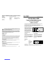
Transition Networks C/A-CF-02 media converters connect twisted-pair copper cable to multimode OR singlemode fiber optic cable, providing network connection through RJ-45 twisted-pair ATM connector and SC connector. With a 5-year warranty, these converters ensure reliable data transmission between ATM devices over extended distances, making them suitable for applications like connecting ATM switches and NICs in various network setups.
Transition Networks C/A-CF-02 media converters connect twisted-pair copper cable to multimode OR singlemode fiber optic cable, providing network connection through RJ-45 twisted-pair ATM connector and SC connector. With a 5-year warranty, these converters ensure reliable data transmission between ATM devices over extended distances, making them suitable for applications like connecting ATM switches and NICs in various network setups.


-
 1
1
-
 2
2


Transition Networks C/A-CF-02 User manual
- Type
- User manual
Transition Networks C/A-CF-02 media converters connect twisted-pair copper cable to multimode OR singlemode fiber optic cable, providing network connection through RJ-45 twisted-pair ATM connector and SC connector. With a 5-year warranty, these converters ensure reliable data transmission between ATM devices over extended distances, making them suitable for applications like connecting ATM switches and NICs in various network setups.
Ask a question and I''ll find the answer in the document
Finding information in a document is now easier with AI
Related papers
-
Transition Networks A-CF-01(SM) User manual
-
-
-
Milan Technology CERTXFX01(SM) User manual
-
-
Transition Networks CSDTF1013-100 User manual
-
-
-
-