Tyco 0-1591500-x Product User Manual
- Category
- Networking
- Type
- Product User Manual
This manual is also suitable for

Tyco SNMP Managed Media Converters Page 1
SNMP Managed Media Converter
Chassis and Converters
___
Product User Guide
Chassis Product Number
0-1591500-x
0-1591500-x ©Tyco Electronics 2004 Issue 1.2

Tyco SNMP Managed Media Converters Page 2
0-1591500-x ©Tyco Electronics 2004 Issue 1.2
Table Of Contents
Introduction....................................................................................................4
Features ................................................................................................................ 5
Software Features ................................................................................................. 5
Disclaimer.............................................................................................................. 6
Warranty................................................................................................................ 6
Getting Support ..................................................................................................... 7
Package Contents ................................................................................................. 8
Management Methods ...................................................................................9
Console Management............................................................................................ 9
Telnet Management............................................................................................... 9
Web Based Management ...................................................................................... 9
SNMP Network Management ................................................................................ 9
Hardware Description..................................................................................10
Front & Rear Panel .............................................................................................. 10
Installation....................................................................................................11
Pre-Installation Requirements.............................................................................. 11
DC Power Supply Connections ........................................................................ 11
Desktop Installation ............................................................................................. 12
Rack-mounted Installation ................................................................................... 12
Applying Power.................................................................................................... 13
Simple Diagnostic Test ........................................................................................ 13
Quick Start Guide.........................................................................................14
LED Indicators ..................................................................................................... 15
Management Card LED Indicators ................................................................... 15
Media Converter LEDs ..................................................................................... 16
Detailed Configuration ................................................................................18
Using a Local Console to Connect to the Chassis................................................ 18
Logging into the Chassis.................................................................................. 18
Main Menu........................................................................................................... 19
Device Settings Menu.......................................................................................... 21
Modules Settings Menu ....................................................................................... 23
Redundant Power Status Menu ........................................................................... 24
Event Log Menu .................................................................................................. 25
SNMP Trap Menu................................................................................................ 27
Secure IP for Telnet, HTTP and SNMP Menu...................................................... 28

Tyco SNMP Managed Media Converters Page 3
0-1591500-x ©Tyco Electronics 2004 Issue 1.2
Save Current Settings Command ........................................................................ 29
Factory Default Settings & Reboot System Command......................................... 29
Reboot System Command................................................................................... 29
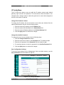
Web-Based Management ............................................................................30
System Login....................................................................................................... 30
Modules Settings Menu ....................................................................................... 32
Module Controls............................................................................................... 33
UTP (RJ-45) Port Controls ............................................................................... 33
Fibre Port Controls ........................................................................................... 34
Notes Field....................................................................................................... 34
Apply Settings .................................................................................................. 34
Save Configuration Settings............................................................................. 34
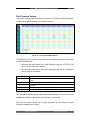
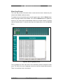
Port Counters Screen .......................................................................................... 35
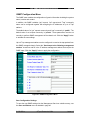
IP Config Menu.................................................................................................... 36
Change The IP Address Values ....................................................................... 36
Change User And/Or Password ....................................................................... 36
Save Configuration Settings............................................................................. 36
SNMP Configuration Menu .................................................................................. 37
Save Configuration Settings............................................................................. 37
Event Log Screen ................................................................................................ 38
Misc Settings Screen ........................................................................................... 39
Save and Reboot Menu ....................................................................................... 40
Save Current Settings ...................................................................................... 40
Factory Default Settings & Reboot ................................................................... 40
Reboot System................................................................................................. 41
Upgrade Firmware Menu ..................................................................................... 41
Web Browser Java Settings........................................................................42
Additional Notes............................................................................................... 45
Product Specifications ................................................................................49

Tyco SNMP Managed Media Converters Page 4
Introduction
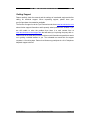
This professional grade, managed media converter chassis solution enables LAN
workgroups and network users to be connected by a fibre path to remote switches,
routers and servers etc. The Ethernet circuits passing through the chassis are fully
managed and enable the network manager to have a high degree of control over the
system.
Link defects and other circuit problems are promptly reported to enable the network
manager to manage and control the network to a much higher level than using basic
un-managed media converters.
The distant end optical devices can be any 100Base-FX or Gigabit Ethernet media
converter or LAN switch/router port. These remote devices cannot controlled or
configured by this SNMP managed chassis product.
Meeting all the relevant standards for 10Mbit/s, 100Mbit/s and Gigabit Ethernet,
installation is ‘plug-and-play’ and requires no technical knowledge.
The hot-swappable managed media converters cards support ST, MT-RJ and SC
single and multimode fibre formats.
With support for hot-swappable management card, dual-redundant and hot-swappable
AC and DC power packs, this managed chassis system delivers a very robust solution
for critical applications.
16
1
Figure 1 - Typical Managed System
0-1591500-x ©Tyco Electronics 2004 Issue 1.2

Tyco SNMP Managed Media Converters Page 5
0-1591500-x ©Tyco Electronics 2004 Issue 1.2
Features
• Chassis supports up to 16 hot swappable media converter cards
• Fully manageable through Web browser, Telnet, SNMP or console interfaces
• Compatible with all standard 100Mbits/s and Gigabit optical interfaces
• Supports full and half-duplex auto-negotiation together with N-Way capability
on all STP/UTP ports
• Link Loss Forwarding fully supported
• Integral event log
• SNMP traps fully supported
• SNMP MIB II and private MIB
• Management security by secure IP address mode
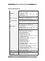
Software Features
Management
Telnet, Web, and Console (RS-232)
MIBS
RFC 1213 MIB II, Private MIB
Software Upgrade
Firmware upgrade via web interface
Link Lost Forward
Each module can be configured to support link loss
forwarding using the Web or console menu interfaces.
Management
Telnet, Web and Console (RS-232)
SNMP Trap Node
Up to 4 Traps supported.
SNMP Trap
SNMP traps support :- Link down, Link up, Power module
status change, authorization fail, Module plug in and plug
out, chassis configuration change, module configuration
change.
IP security
IP security support for telnet, HTTP and SNMP access.
Up to 4 different IP addresses can be supported.
Events log
Up to 4095 events can be recorded.
Table 1 – Key Software Features

Tyco SNMP Managed Media Converters Page 6
0-1591500-x ©Tyco Electronics 2004 Issue 1.2
Disclaimer
Tyco Electronics makes no representation or warranties with respect to the contents
hereof and specifically disclaims any implied warranties or merchantability or fitness
for any particular purpose. Further, Tyco Electronics reserves the right to revise this
publication and make changes from time-to-time in the content hereof without
obligation of Tyco Electronics to notify any person of such revision or changes.
Warranty
Full details of the generic limited lifetime warranty scheme are available on the web
site at:-
http://www.lan-electronics.com/support.htm
Tyco Electronics (Active LAN Products) warrants its products to be free from defects in
material and workmanship, under normal use and operation for the lifetime of the
product from the date of purchase from an authorised vendor, subject to the conditions
and exclusions below:-
1. This warranty does not cover any damage to the products that resulted from
accident, abuse, misuse, natural or personal disaster, or any unauthorised
disassembly or modification, or operation in a manner contrary to the instructions,
or shipment of the product to the Tyco Support Centre.
2. The products are not designed, manufactured or intended for use in hazardous or
critical environments or in activities requiring emergency or fail-safe operation or in
any other activity or application in which failure of the product may pose the risk of
physical injury or death or environmental harm. Tyco Electronics (Active LAN
Products) specifically disclaims any express or implied warranty of fitness for any
dangerous application.
3. Except for the foregoing express limited warranty, Tyco makes no other warranty,
statutory, express or implied, including, but not limited to, warranties of
merchantability or fitness for a particular purpose.
4. Tyco Electronics (Active LAN Products) offers a two-year standard warranty to
internal or external power supply units and cooling fans, where fitted. This standard
warranty commences from the date that the end Customer purchases the unit from
an authorised vendor.

Tyco SNMP Managed Media Converters Page 7
0-1591500-x ©Tyco Electronics 2004 Issue 1.2
Getting Support
Please carefully check the manual and the settings of associated equipment before
calling for technical support. When requesting support, please have your
proof-of-purchase documentation available.
The first line of support is via the Tyco Electronics web site at
www.lan-electronics.com
where further support information and frequently asked questions are located. If you
are still unable to solve the problem then there is a web contact form at
www.lan-electronics.com/support.htm that will assist you in placing the query with us.
Please fill in all the fields and provide us with as much information as possible to assist
us in getting a suitable answer to you. The estimated turn-round time for support
requests is 1-2 working days. Partner level clients may participate in a 24 x 5 telephone
helpdesk support scheme.

Tyco SNMP Managed Media Converters Page 8
Package Contents
Unpack the carton of the Tyco SNMP managed converter chassis and check contents
as listed below :-
n Tyco SNMP Managed Converter Chassis with AC Power Supply
n AC Power Cord
n Four adhesive rubber feet
n RS-232 cable
n User Guide
n Rack mount kit
Tyco SNMP Managed Converter Chassis Rubber Feet Rack-mount Kit
Manual
RS-232 cable User Guide Power Cord
Figure 2 – Package contents
Compare the contents of your Tyco SNMP managed converter package with the
checklist above. If any item is missing or damaged, please contact your local dealer for
service.
0-1591500-x ©Tyco Electronics 2004 Issue 1.2

Tyco SNMP Managed Media Converters Page 9
0-1591500-x ©Tyco Electronics 2004 Issue 1.2
Management Methods
The Tyco SNMP managed media converter chassis supports the following
management methods:
n Console Management
n Telnet Management
n Web-based Management
n SNMP Network Management
Console Management
The chassis can be managed by the RS-232 Console Port on the Management Card
using a terminal emulation or other program on a PC. A range of simple text based
menus guides the user through the configuration process. See page 15.
Telnet Management
The chassis can be remotely managed over the network using a standard Telnet client
that is available in most PCs and workstations. Telnet can be used to log in and control
the chassis configuration. The same format menus as used in the Console
Management are displayed. Note that the Telnet session remains active until the
session is closed at the client.
Web Based Management
The chassis can be managed using a standard web browser that supports Java
applets. This interface has the same functionality as the console/Telnet interfaces but
is more user-friendly. The chassis can be managed from anywhere on the network
through a standard browser such as Microsoft Internet Explorer. See page 30.
SNMP Network Management
SNMP (Simple Network Management Protocol) provides a means to monitor and
control a network device, and to manage configurations, statistic collection,
performance and security.
Data is passed from SNMP agents, which are hardware and software processes
reporting activity in each network device to the workstation console used to oversee
the network. The agent returns information contained in a MIB (Management
Information Base), which is a data structure that defines the device and what can be
controlled.

Tyco SNMP Managed Media Converters Page 10
Hardware Description
The Tyco SNMP Managed Converter Chassis is a modular unit that contains 16
converter slots and 2 power slots. The chassis is provided with a plug-in management
card. The RS-232 port is used for local management and the Ethernet RJ-45
connector is for In-band management via Telnet, SNMP or web browser. Both these
physical interfaces are on the front panel of the management card.
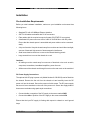
Front & Rear Panel
The front panel of the SNMP Managed Converter Chassis is shown below fully
populated with the Management card in the far left hand slot and then 16 plug-in fibre
media converter cards in slots numbered 1…16 towards the right.
Figure 3 – SNMP Managed Media Converter Chassis - Front View
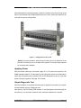
The standard IEC power socket is located at the rear panel of the Tyco SNMP
managed converter chassis. The AC power range is 100-240VAC, 50-60Hz and the
DC power range is 40.5 ~57.0V. Two power supply units of either AC or DC type can
be installed in the chassis. The factory default chassis is supplied with one AC power
module unit and one fan unit.
Power Slot B is installed with
a fan unit by default.
0-1591500-x ©Tyco Electronics 2004 Issue 1.2
Figure 4 –SNMP Managed Media Converter Chassis - Rear View
Power Slot A is fitted with
an AC Power Module

Tyco SNMP Managed Media Converters Page 11
0-1591500-x ©Tyco Electronics 2004 Issue 1.2
Installation
Pre-Installation Requirements
Before you start hardware installation, make sure your installation environment has
following items:
• Standard PC with 10/100Mbps Ethernet interface
• S/UTP LAN cables terminated with RJ-45 connectors.
• Fibre cables with the required connector formats (SC/ST/MT-RJ connectors)
• A dedicated AC power source at 100 to 240V AC at 50/60 Hz or 48v DC power.
Ensure that the chassis power is accessible and power cables can be connected
easily.
• A dry cool location. Keep the chassis away from moisture and avoid direct sunlight,
sources of heat and high amount of electromagnetic interference.
• Small cross-head screw driver to remove the chassis blanking panels
• Large screw driver to mount the chassis in a rack.
Cautions:
• All cabling must be routed away from sources of electrical noise such as radio,
computers, transmitters, broadband amplifiers, power lines etc.
• Airflow around the chassis and through its vents on the rear must not be restricted.
DC Power Supply Connections
The optional 48v DC plug-in power unit (Model Number 0-1591506-0) can be fitted into
the chassis. Remove the fan unit from the chassis unit and carefully insert the DC
power unit into the chassis. Secure the power unit with screws. The DC power supply
has a set of screw terminals on the rear of the power unit. Secure the supply leads to
these screw terminals using spade style connections.
• Connect the 0v or negative of the DC supply to the screw marked GND
• Connect the +48v or positive of the DC supply to the screw marked VIN
Ensure that the input DC supply is floating with respect to chassis to avoid ground
loops.

Tyco SNMP Managed Media Converters Page 12
Desktop Installation
Set the chassis on a sufficiently large flat space with a power outlet nearby, and near
the centre of all networked devices. Make sure mounting surface on the bottom of the
chassis is grease and dust free. Remove the adhesive backing from the supplied
rubber feet.
Figure 5 – Fitting Rubber Feet
Apply the rubber feet to each corner on the bottom of the chassis. These footpads can
prevent the chassis from shock/vibrations.
Caution: Do not place objects on top of the chassis unit or obstruct the side vents.
Rack-mounted Installation
The SNMP Managed converter chassis is supplied with a rack-mounted kit and can be
mounted in an EIA standard size, 19-inch rack. The chassis can be placed in a wiring
closet with other equipment.
Perform the following steps to rack mount the chassis:
• Position one bracket to align with the holes on one side of the chassis and
secure it with the smaller bracket screws.
• Then attach the remaining bracket to the other side of the chassis.
Figure 6 – Fitted Rack Mounted Ears
0-1591500-x ©Tyco Electronics 2004 Issue 1.2

Tyco SNMP Managed Media Converters Page 13
After attaching both mounting brackets, position the chassis in the rack by lining up the
holes in the brackets with the appropriate holes on the rack. Secure the chassis to the
rack with the rack-mounting screws.
Figure 7 – Fitting Chassis into a rack
[Note] For proper ventilation, allow at least 4 inches (10 cm) of clearance on the
front and 3.4 inches (8 cm) on the back of the chassis. This is especially important
for enclosed rack installation.
Applying Power
After all network cables are connected, apply AC or DC power as required to the
SNMP managed chassis. Turn the power on using the power switch on the back panel.
Check the front panel power indicator LEDs on the Management Card to verify that
power is properly supplied. See page 15 for details.
Simple Diagnostic Test
After the installation is completed and the power is applied to the chassis, the system
will automatically perform a diagnostic test.
After boot-up, the CPU Ready LED indicator on the Management Card will toggle on
and off every 3~5 seconds if media converter cards are installed in the chassis.
0-1591500-x ©Tyco Electronics 2004 Issue 1.2

Tyco SNMP Managed Media Converters Page 14
0-1591500-x ©Tyco Electronics 2004 Issue 1.2
Quick Start Guide
The steps below are intended to guide the technically competent user through the
initial configuration of the SNMP chassis for both Telnet and Web based management
systems. For full details of these steps, see the relevant sections of the manual.
1. Place the chassis into a safe environment suitable for testing the key functions.
2. Fit at least one media converter card into the chassis and apply power to the
chassis. Ensure that the LED indicators are lit as detailed in the tables on pages 15
and 16.
3. Connect a PC serial console port to the chassis using the supplied RS232 cable as
described in page 18.
4. Start the terminal emulation program on the PC and check that the basic console
menu is displayed as described on page 18.
5. Log into the chassis by using the default user name of root and the default
password of root.
6. Change the IP address details for the chassis by selecting option 1 – Device
Settings menu and then options 4, 5 and 6 to apply the new IP address, subnet
mask and default gateway values. The network administrator should provide these
values.
7. Save these new settings and reboot the switch by selecting S and then R on the
Main menu.
8. Connect the Ethernet LAN port of the Management Card to the network and check
that the chassis responds to “ping requests” directed to the programmed IP
address. See page 45 for further information.
9. Open a Telnet session on the PC and specify the chassis programmed IP address.
The Main menu screen should be displayed.
10. Open a web browser session and specify the chassis IP address. It may be
necessary to apply the browser security settings detailed on page 42 if the browser
does not display the correct image of the populated chassis.
11. Use the Module Settings screen of the browser to select the required media
converter card. Check that the displayed settings match the expected values.
12. Apply the required configuration values to the media converters and chassis unit.
13. Save the new settings using the Save& Reboot menu.

Tyco SNMP Managed Media Converters Page 15
LED Indicators
All LED status indicators are located on the front panel of the chassis. These indicators
provide real-time indication of system and operational status.
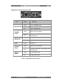
Management Card LED Indicators
LED Status Meaning
CPU Ready Slow Flash The management card is working correctly
CPU Ready Green
The management card has failed or no
modules are fitted in the chassis
PWR
Green Power on
Green External Power supplied to PSU A
Good A
Off
No External power supplied to PSU A or
PSU A not fitted
Green External Power supplied to PSU B
Good B
Off
No External power supplied to PSU B or
PSU B not fitted
Orange Power unit A has failed
Fail A
Off Power unit A is ready
Orange Power unit B has failed
Fail B
Off Power unit B is ready
Green
Ethernet port is connected to an external
device.
LK/ACT
Flash The port is receiving or transmitting data
Yellow Ethernet link in Full Duplex mode
FDX
Flash Collision of Packets occurs in the port.
Table 2 – Management Card LED Indications
0-1591500-x ©Tyco Electronics 2004 Issue 1.2

Tyco SNMP Managed Media Converters Page 16
Media Converter LEDs
10/100Mbits/s Ethernet Media Converter LEDs
LED Status Meaning
Speed (RJ-45)
Green Link operating in 100Mbps mode
Green Ethernet Link connected
LINK/ACT
(RJ-45)
Flash
The port is receiving or transmitting data
on the RJ-45 port.
Orange In Full Duplex mode
Flash
Collision of Packet has occurred on this
port
FDX/COL
(RJ-45)
Off Half Duplex mode
Power
Green Power On
Green Fibre Link connected
LINK/ACT
(Fibre)
Flash
The port is receiving or transmitting data
on the fibre port.
Green Port In Full Duplex mode
Flash
Collision of Packet has occurred on this
port
FDX/COL
(Fibre)
Off Port In Half Duplex mode
Table 3 – Module LED Indications
0-1591500-x ©Tyco Electronics 2004 Issue 1.2

Tyco SNMP Managed Media Converters Page 17
Gigabit Ethernet Media Converter LEDs
LED Status Meaning
Green Link in 1000Mbps mode
Orange Link in 100Mbps mode
Speed (RJ-45)
Off Link in 10Mbps mode
Green Ethernet Link connected
LINK/ACT
(RJ-45)
Flash
The port is receiving or transmitting data on
the RJ-45 port.
Orange In Full Duplex mode
FDX (RJ-45)
Off Half Duplex mode
Power
Green Power On
Green Ethernet Link connected
LINK/ACT
(Fibre)
Flash
The port is receiving or transmitting data on
the RJ-45 port.
Green In Full Duplex mode
FDX/COL
(Fibre)
Off In Half Duplex mode
Table 4 – Gigabit Module LED indications
0-1591500-x ©Tyco Electronics 2004 Issue 1.2

Tyco SNMP Managed Media Converters Page 18
Detailed Configuration
Using a Local Console to Connect to the Chassis
The console port is a male DB-9 connector located on the front panel of the chassis
management card. This port enables a connection to a PC or terminal for monitoring
and configuration. Use the supplied RS-232 cable with a female DB-9 connector to
connect a terminal or PC to the Console port.
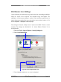
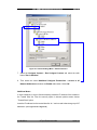
After connection to the Console port, turn on the PC or terminal and configure its
communications parameters to match the following default characteristics of the
console port:
Baud Rate: 9600 bps
Data Bits: 8
Parity: None
Stop Bit: 1
Flow control: None
Figure 8 – Terminal Settings
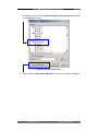
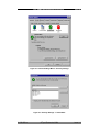
Logging into the Chassis
Hyper Terminal
TM
or other terminal emulation programs can be used with the above
settings for Console management. After communication has been achieved the user
will be prompted for a login user name and password.
Default login user name: root
Default login password: root
Note: User lower case letters only to enter the default user name and password.
0-1591500-x ©Tyco Electronics 2004 Issue 1.2

Tyco SNMP Managed Media Converters Page 19
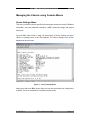
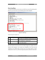
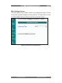
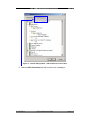
Main Menu
After the user has logged on they will be prompted to enter “m” to enter the main menu.
The following console style screen is then displayed:-
Figure 9 – Console Main Menu Screen
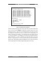
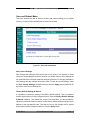
The Main menu is the top-level menu for the console and Telnet interfaces. The
options are:-
Figure 10 – Console and Telnet Menu Tree
0-1591500-x ©Tyco Electronics 2004 Issue 1.2

Tyco SNMP Managed Media Converters Page 20
0-1591500-x ©Tyco Electronics 2004 Issue 1.2
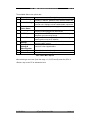
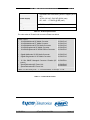
The available Main menu options are:-
No. Menu Item Description
1
Device Settings
Configure and view the settings for the chassis unit
including IP address, password, user interface modes etc.
2
Module Settings
Configure and view the settings for the selected media
converter unit. Settings include enable/disable, speed etc.
3
Redundant
Power Status
View the status of both power supply units.
4
Event Log
Enable and view the event log that displays detected faults
including module plugged out, fibre fail etc.
5
SNMP Trap
Configure the SNMP trap sub-system including trap
addresses and community strings.
6
Secure IP
Configure IP addresses that are permitted to manage the
chassis system over the IP network.
S
Save Current
Settings
Saves all settings of the chassis and media converter cards
into non-volatile memory.
D
Factory Default
Settings &
Reboot System
Selectively restore the factory default conditions to reset all
controls to a the shipped status.
R
Reboot System
Reboots the chassis and media converter modules.
Q
Quit
Exit the Main menu and log off
Table 5- Main Menu Options
After selecting a menu item (from the range 1..6, S,D,R and Q) enter the <CR> or
<Return> key on the PC to activate the item.
Page is loading ...
Page is loading ...
Page is loading ...
Page is loading ...
Page is loading ...
Page is loading ...
Page is loading ...
Page is loading ...
Page is loading ...
Page is loading ...
Page is loading ...
Page is loading ...
Page is loading ...
Page is loading ...
Page is loading ...
Page is loading ...
Page is loading ...
Page is loading ...
Page is loading ...
Page is loading ...
Page is loading ...
Page is loading ...
Page is loading ...
Page is loading ...
Page is loading ...
Page is loading ...
Page is loading ...
Page is loading ...
Page is loading ...
Page is loading ...
-
 1
1
-
 2
2
-
 3
3
-
 4
4
-
 5
5
-
 6
6
-
 7
7
-
 8
8
-
 9
9
-
 10
10
-
 11
11
-
 12
12
-
 13
13
-
 14
14
-
 15
15
-
 16
16
-
 17
17
-
 18
18
-
 19
19
-
 20
20
-
 21
21
-
 22
22
-
 23
23
-
 24
24
-
 25
25
-
 26
26
-
 27
27
-
 28
28
-
 29
29
-
 30
30
-
 31
31
-
 32
32
-
 33
33
-
 34
34
-
 35
35
-
 36
36
-
 37
37
-
 38
38
-
 39
39
-
 40
40
-
 41
41
-
 42
42
-
 43
43
-
 44
44
-
 45
45
-
 46
46
-
 47
47
-
 48
48
-
 49
49
-
 50
50


Tyco 0-1591500-x Product User Manual
- Category
- Networking
- Type
- Product User Manual
- This manual is also suitable for
Ask a question and I''ll find the answer in the document
Finding information in a document is now easier with AI
Related papers
Other documents
-
 Tyco Electronics 0-15910 Series User manual
-
CTS MCT-RACK-18 Installation guide
-
Tyco Electronics 24 Port SNMP User manual
-
 Tyco Electronics 0-1591700 Series User manual
-
Repotec RP-MCSNMP Owner's manual
-
MicroNet SP1387 User manual
-
Longshine LCS-C819 User manual
-
Trendnet TFC-1600MM User manual
-
-
 AAxeon Optolinx FCU-RACK16 User manual


