Western Telematic IPS-1600-D20 User manual
- Category
- Networking
- Type
- User manual
This manual is also suitable for

WTI Part No.: 13614
Rev. A
IPS-800/1600-D20 Series
Internet Power Switches
Models:
IPS-800-D20
IPS-800E-D20
IPS-1600-D20
IPS-1600E-D20
User’s Guide


i
Warnings and Cautions:
INSTALLATION INSTRUCTIONS
SECURE RACKING
If Secure Racked units are installed in a closed or multi-unit rack assembly, they may require
further evaluation by Certification Agencies. The following items must be considered.
1. The ambient within the rack may be greater than room ambient. Installation should be such
that the amount of air flow required for safe operation is not compromised. The maximum
temperature for the equipment in this environment is 45°C. Consideration should be given to
the maximum rated ambient.
2. Installation should be such that a hazardous stability condition is not achieved due to
uneven loading.
INPUT SUPPLY
Check nameplate ratings to assure there is no overloading of supply circuits that could have an
effect on overcurrent protection and supply wiring.
GROUNDING
Reliable earthing of this equipment must be maintained. Particular attention should be given
to supply connections when connecting to power strips, rather than direct connections to the
branch circuit.
No Serviceable Parts Inside; Authorized Service Personnel Only
Do not attempt to repair or service this device yourself. Internal components must be serviced by
authorized personnel only.
• Shock Hazard - Do Not Enter
Disconnect Power
If any of the following events are noted, immediately disconnect the unit from the outlet and
contact qualified service personnel:
1. If the power cord becomes frayed or damaged.
2. If liquid has been spilled into the device or if the device has been exposed to rain or water.
Two Power Supply Cables
Note that this unit features two separate power circuits, which require a power supply cable for
each circuit. Before attempting to service or remove this unit, please make certain that both power
cables are disconnected.

ii
IPS-800/1600-D20 Series - User’s Guide
FCC Part 15 Regulation
This equipment has been tested and found to comply with the limits for a Class A digital device,
pursuant to Part 15 of the FCC rules. These limits are designed to provide reasonable protection
against harmful interference in a residential installation. This equipment generates, uses, and can
radiate radio frequency energy, and if not installed and used in accordance with the instructions,
may cause harmful interference to radio communications. However, there is no guarantee that
interference will not occur in a particular installation. If this equipment does cause harmful
interference to radio or television reception, which can be determined by turning the equipment
off and on, the user is encouraged to try to correct the interference by one or more of the following
measures:
• Reorient or relocate the receiving antenna.
• Increase the separation between the equipment and receiver.
• Plug the equipment into an outlet on a circuit that is different from the one used by the
receiver.
• Consult the dealer or an experienced radio/TV technician for help.
This device complies with Part 15 of the FCC rules. Operation of this device is subject to the
following conditions: (1) This device may not cause harmful interference, and (2) this device must
accept any interference that may cause undesired operation.
WARNING: Changes or modifications to this unit not expressly approved by the
party responsible for compliance could void the user’s authority to operate the
equipment
Industry Canada - EMI Information
This Class A digital apparatus complies with Canadian ICES-003.
Cet appareil numérique de la classe A est conforme à la norme NMB-003 du Canada.

i
Table of Contents
1. Introduction . . . . . . . . . . . . . . . . . . . . . . . . . . . . . . . . . . . . . . . . . . . . . . . . . . . . . . . . . . 1-1
2. Unit Description
. . . . . . . . . . . . . . . . . . . . . . . . . . . . . . . . . . . . . . . . . . . . . . . . . . . . . . . 2-1
3. Quick Start
. . . . . . . . . . . . . . . . . . . . . . . . . . . . . . . . . . . . . . . . . . . . . . . . . . . . . . . . . . . 3-1
3.1. Hardware Installation . . . . . . . . . . . . . . . . . . . . . . . . . . . . . . . . . . . . . . . . . . . . . . . 3-1
3.1.1. Apply Power to the IPS . . . . . . . . . . . . . . . . . . . . . . . . . . . . . . . . . . . . . . 3-1
3.1.2. Connect your PC to the IPS . . . . . . . . . . . . . . . . . . . . . . . . . . . . . . . . . . . 3-2
3.2 Communicating with the IPS . . . . . . . . . . . . . . . . . . . . . . . . . . . . . . . . . . . . . . . . . 3-2
4. Installation
. . . . . . . . . . . . . . . . . . . . . . . . . . . . . . . . . . . . . . . . . . . . . . . . . . . . . . . . . . . 4-1
4.1. Power Supply Connection . . . . . . . . . . . . . . . . . . . . . . . . . . . . . . . . . . . . . . . . . . . 4-1
4.1.1. Installing the Cable Keepers . . . . . . . . . . . . . . . . . . . . . . . . . . . . . . . . . . 4-1
4.2. Connection to Switched Outlets . . . . . . . . . . . . . . . . . . . . . . . . . . . . . . . . . . . . . . . 4-2
4.3. Serial COM / RS232 Port Connection . . . . . . . . . . . . . . . . . . . . . . . . . . . . . . . . . . 4-3
4.3.1. Connecting a Local PC . . . . . . . . . . . . . . . . . . . . . . . . . . . . . . . . . . . . . . 4-3
4.3.2. Connecting an External Modem . . . . . . . . . . . . . . . . . . . . . . . . . . . . . . . 4-3
4.4. Connecting the Network Cable . . . . . . . . . . . . . . . . . . . . . . . . . . . . . . . . . . . . . . . 4-3
5. Configuration
. . . . . . . . . . . . . . . . . . . . . . . . . . . . . . . . . . . . . . . . . . . . . . . . . . . . . . . . . 5-1
5.1. System Mode and User Mode . . . . . . . . . . . . . . . . . . . . . . . . . . . . . . . . . . . . . . . . 5-1
5.2. Communicating with the IPS . . . . . . . . . . . . . . . . . . . . . . . . . . . . . . . . . . . . . . . . . 5-2
5.2.1. Accessing the Web Browser Interface . . . . . . . . . . . . . . . . . . . . . . . . . . . 5-2
5.2.2. Accessing the Text Interface . . . . . . . . . . . . . . . . . . . . . . . . . . . . . . . . . . 5-3
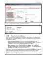
5.3. Configuration Menus . . . . . . . . . . . . . . . . . . . . . . . . . . . . . . . . . . . . . . . . . . . . . . . 5-5
5.3.1. The General Parameters Menus . . . . . . . . . . . . . . . . . . . . . . . . . . . . . . . . 5-6
5.3.2. The Serial Parameters Menu . . . . . . . . . . . . . . . . . . . . . . . . . . . . . . . . . . 5-9
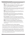
5.3.3. Plug Parameters Menus . . . . . . . . . . . . . . . . . . . . . . . . . . . . . . . . . . . . . 5-11
5.3.3.1. Plug Passwords and Co-Location Features . . . . . . . . . . . . . . . 5-12
5.3.3.2. The Boot / Sequence Delay Period. . . . . . . . . . . . . . . . . . . . . . 5-13
5.3.4. Network Parameters Menus . . . . . . . . . . . . . . . . . . . . . . . . . . . . . . . . . . 5-15
5.3.4.1. IP Security Feature . . . . . . . . . . . . . . . . . . . . . . . . . . . . . . . . . . 5-16
5.3.5. The Telnet Parameters Menus . . . . . . . . . . . . . . . . . . . . . . . . . . . . . . . . 5-18
5.3.6. Web Server Parameters Menus . . . . . . . . . . . . . . . . . . . . . . . . . . . . . . . 5-19
5.4. Save Configuration Parameters . . . . . . . . . . . . . . . . . . . . . . . . . . . . . . . . . . . . . . 5-20
6. Operation
. . . . . . . . . . . . . . . . . . . . . . . . . . . . . . . . . . . . . . . . . . . . . . . . . . . . . . . . . . . . 6-1
6.1. Operation via the Web Browser Interface . . . . . . . . . . . . . . . . . . . . . . . . . . . . . . . 6-1
6.1.1. The Plug Status Screen - Web Browser Interface . . . . . . . . . . . . . . . . . . 6-1
6.2. Operation via the Text Interface . . . . . . . . . . . . . . . . . . . . . . . . . . . . . . . . . . . . . . . 6-3
6.2.1. The Plug Status Screen - Text Interface . . . . . . . . . . . . . . . . . . . . . . . . . . 6-3
6.2.2. Switching and Reboot Commands - Text Interface . . . . . . . . . . . . . . . . . 6-4
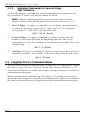
6.2.3. Applying Commands to Several Plugs - Text Interface . . . . . . . . . . . . . . 6-6
6.3. Logging Out of Command Mode . . . . . . . . . . . . . . . . . . . . . . . . . . . . . . . . . . . . . . 6-6
6.4. The Automated Mode . . . . . . . . . . . . . . . . . . . . . . . . . . . . . . . . . . . . . . . . . . . . . . . 6-7
6.5. Manual Operation . . . . . . . . . . . . . . . . . . . . . . . . . . . . . . . . . . . . . . . . . . . . . . . . . 6-8
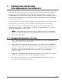
7. Saving and Restoring Configuration Parameters
. . . . . . . . . . . . . . . . . . . . . . . . . . . . 7-1
7.1. Sending Parameters to a File . . . . . . . . . . . . . . . . . . . . . . . . . . . . . . . . . . . . . . . . . 7-1
7.2. Restoring Saved Parameters . . . . . . . . . . . . . . . . . . . . . . . . . . . . . . . . . . . . . . . . . . 7-2
8. Upgrading the IPS Firmware
. . . . . . . . . . . . . . . . . . . . . . . . . . . . . . . . . . . . . . . . . . . . 8-1

ii
IPS-800/1600-D20 Series - User’s Guide
Appendices:
A. Interface Description
. . . . . . . . . . . . . . . . . . . . . . . . . . . . . . . . . . . . . . . . . . . . . . . . . Apx-1
A.1. Serial COM / RS232 Port Interface . . . . . . . . . . . . . . . . . . . . . . . . . . . . . . . . . . Apx-1
B. Specifications . . . . . . . . . . . . . . . . . . . . . . . . . . . . . . . . . . . . . . . . . . . . . . . . . . . . . . . .
Apx-2
C. Customer Service
. . . . . . . . . . . . . . . . . . . . . . . . . . . . . . . . . . . . . . . . . . . . . . . . . . . . Apx-3
Index . . . . . . . . . . . . . . . . . . . . . . . . . . . . . . . . . . . . . . . . . . . . . . . . . . . . . . . . . . . . . . . . . .Index-1
List of Figures
2.1. IPS-800 Back Panel (120 VAC Model Shown) . . . . . . . . . . . . . . . . . . . . . . . . . . . . . . . 2-1
2.2. IPS-1600 Back Panel (120 VAC Model Shown)
. . . . . . . . . . . . . . . . . . . . . . . . . . . . . . 2-1
3.1. Plug Status Screen - Web Browser Interface (IPS-800 Shown) . . . . . . . . . . . . . . . . . . .
3-3
3.2. Plug Status Screen - Text Interface (IPS-800 Shown)
. . . . . . . . . . . . . . . . . . . . . . . . . . 3-3
5.1. Plug Status Screen - Web Browser Interface (IPS-800 Shown) . . . . . . . . . . . . . . . . . . .
5-2
5.2. Plug Status Screen - Text Interface (IPS-800 Shown)
. . . . . . . . . . . . . . . . . . . . . . . . . . 5-4
5.3. General Parameters Menu - Web Browser Interface . . . . . . . . . . . . . . . . . . . . . . . . . . . .
5-6
5.4. General Parameters Menu - Text Interface . . . . . . . . . . . . . . . . . . . . . . . . . . . . . . . . . . .
5-7
5.5. Serial Parameters Menu - Web Browser Interface
. . . . . . . . . . . . . . . . . . . . . . . . . . . . . 5-9
5.6. Serial Parameters Menu - Text Interface . . . . . . . . . . . . . . . . . . . . . . . . . . . . . . . . . . . . .
5-9
5.7. Plug Parameters Menu - Web Browser Interface
. . . . . . . . . . . . . . . . . . . . . . . . . . . . . 5-11
5.8. Plug Parameters Menu - Text Interface
(Plug 1 Shown) . . . . . . . . . . . . . . . . . . . . . . . . 5-11
5.9. Network Parameters Menu - Web Browser Interface . . . . . . . . . . . . . . . . . . . . . . . . . .
5-14
5.10. Network Parameters Menu - Text Interface
. . . . . . . . . . . . . . . . . . . . . . . . . . . . . . . . . 5-14
5.11. IP Security Menu - Text Interface . . . . . . . . . . . . . . . . . . . . . . . . . . . . . . . . . . . . . . . . .
5-16
5.12. Telnet Parameters Menu - Web Browser Interface . . . . . . . . . . . . . . . . . . . . . . . . . . . .
5-18
5.13. Telnet Parameters Menu - Text Interface
. . . . . . . . . . . . . . . . . . . . . . . . . . . . . . . . . . . 5-18
5.14. Web Server Parameters Menu - Web Browser Interface . . . . . . . . . . . . . . . . . . . . . . . .
5-19
5.15. Web Server Parameters Menu - Text Interface . . . . . . . . . . . . . . . . . . . . . . . . . . . . . . .
5-19
6.1. Plug Status Menu - Web Browser Interface (IPS-800 Shown) . . . . . . . . . . . . . . . . . . . .
6-2
6.2. Plug Status Screen - Text Interface (IPS-800 Shown)
. . . . . . . . . . . . . . . . . . . . . . . . . . 6-3
6.3. The IPS Help Screen - Text Interface . . . . . . . . . . . . . . . . . . . . . . . . . . . . . . . . . . . . . . .
6-4
A.1. COM Port Interface . . . . . . . . . . . . . . . . . . . . . . . . . . . . . . . . . . . . . . . . . . . . . . . . . . .
Apx-1

1-1
1. Introduction
Electronic equipment sometimes "locks-up," requiring a service call just to flip
the power switch to perform a simple reboot. The IPS-800/1600-D20 Series
Internet Power Switches give you the ability to perform this function from
anywhere, just point your browser to the IPS’s IP address, enter the secure
password, and you’re just a click away from remote power On, Off or Reboot!
20 Amp Power Control
The IPS-800/1600-D20 Series Internet Power Switch provides plenty of power
for rack mount applications; two separate 20 Amp power circuits provide a
total of 40 Amps per IPS unit.
Intelligent Power Control
In addition to web browser access, the IPS can also communicate over any
TCP/IP network using standard Telnet, or out-of-band using an external
modem and basic VT100 type terminal emulation.
Security Features and Co-Location Features
To ensure security, web browser access requires the user to enter an assigned
user name and password. The IPS provides two levels of operational
passwords; the System Administrator Level, which allows access to all
configuration and switching functions, and the User Level, which only allows
access to assigned plugs and cannot be used to change unit configuration.
In addition to password security features, the IPS also includes an address
specific IP security mask, which can be employed to prevent unauthorized
network access to the IPS command mode.
Easy to Configure, Easy to Use
The IPS can be configured over the network, via modem, or locally via the IPS
COM port. Easy to use commands let you assign a location name, set system
parameters and view plug status. Outlets can be switched On, Off, or booted
using plug numbers or names.
Reliability and Support
The IPS is built in the USA and backed by a two year warranty. NetReach
products are installed in thousands of network sites world wide. Our
customers know they can depend on WTI for superior quality and reliability
for their most mission-critical operations.

1-2
IPS-800/1600-D20 Series - User’s Guide
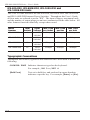
IPS-800-D20, IPS-800E-D20, IPS-1600-D20 and
IPS-1600E-D20 Units
This User’s Guide discusses the IPS-800-D20, IPS-800E-D20, IPS-1600-D20
and IPS-1600E-D20 Internet Power Switches. Throughout this User’s Guide,
all four units are referred to as the "IPS". The input voltages, maximum loads
and the number of output plugs per unit are summarized in the table below. All
other features function identically except where noted.
Model
Number
Total
Outlets
Input
Voltage
Max. Load
per Outlet
Max. Load
per Bus
Max. Load
per Unit
IPS-800-D20 8 100 to
120 VAC
15 Amps 20 Amps 40 Amps
IPS-800E-D20 8 100 to
240 VAC
15 Amps 20 Amps 40 Amps
IPS-1600-D20 16 100 to
120 VAC
15 Amps 20 Amps 40 Amps
IPS-1600E-D20 16 100 to
240 VAC
15 Amps 20 Amps 40 Amps
Typographic Conventions
Throughout this manual, typefaces and characters have been used to denote the
following:
COURIER FONT Indicates characters typed on the keyboard.
For example,
/ON 3 or /OFF 4.
[Bold Font] Text set in bold face and enclosed in square brackets
indicates a specific key. For example,
[Enter] or [Esc].

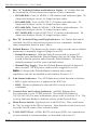
2-1
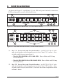
2. Unit Description
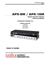
As shown in Figure 2.1 and Figure 2.2, the IPS back panel includes connectors,
LEDs and manual controls described below:
BUS
A
B
A-1 A-2 A-3 A-4 B-5 B-6 B-7 B-8
MAIN POWER
COM
10BaseT
ACT
RDY
ON
DEF
1
2
3
4
5
6
7
8
9
Figure 2.1: IPS-800-D20 Back Panel (120 VAC Model Shown)
➀
Bus "A" Power Inlet and Circuit Breaker: An IEC320-C20 AC inlet
and circuit breaker which supply power to the Circuit "A" outlets. Also
includes cable keeper (not shown.)
• Models IPS-800-D20 & IPS-1600-D20: Power Inlet and 20 Amp
Circuit Breaker.
• Models IPS-800E-D20 & IPS-1600E-D20: Power Inlet and 20 Amp
Circuit Breaker.
➁
Bus "B" Power Inlet and Circuit Breaker: An IEC320-C20 AC inlet
and circuit breaker which supply power to the Circuit "B" outlets. Also
includes cable keeper (not shown.) Includes the same components listed
in Item 1 above.
BUS
A
BUS
B
A-1 A-2 A-3 A-4 A-5 A-6 A-7 A-8
B-9 B-10 B-11 B-12 B-13 B-14 B-15 B-16
MAIN POWER
COM
10BaseT
ACTRDY
ON
DEF
1
2
3
4
5
6
7
8
9
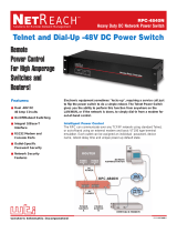
Figure 2.2: IPS-1600-D20 Back Panel (120 VAC Model Shown)

2-2
IPS-800/1600-D20 Series - User’s Guide
➂
Bus "A" Switched Outlets and Indicator Lights: AC Outlets that can
be switched On, Off or rebooted in response to user commands.
• IPS-800-D20: Four (4) NEMA 5-15R Outlets with indicator lights. 20
Amps total load per circuit; 15 Amps load per outlet.
• IPS-800E-D20: Four (4) IEC320-C13 Outlets with indicators. 20
Amps total load per circuit; 15 Amps load per outlet.
• IPS-1600-D20: Eight (8) NEMA 5-15R Outlets with indicators. 20
Amps total load per circuit; 15 Amps load per outlet.
• IPC-1600E-D20: Eight (8) IEC320-C13 Outlets with indicators. 20
Amps total load per circuit; 15 Amps load per outlet.
➃
Bus "B" Switched Plugs and Plug Indicators: AC Outlets that can be
switched On, Off or rebooted in response to user commands. Includes
same components listed in item 3 above.
➄
Default Button: This button can be used to either reset the unit to default
parameters or manually toggle all plugs On or Off:
• Default Parameters: With the Main Power switch set in the Off
position, press and hold the Default Button, then set the Main Power
switch in the On position and release the Default Button. All menu
defined parameters will be reset to default values.
• Manual Plug Toggle: Press the Default Button and hold it down for
three seconds. All IPS power outlets will be toggled On or Off.
Note: If desired, the Default Button’s manual plug control
capabilities can also be disabled as described in Section 5.3.1.
➅
Unit Status Indicators: Two LED Indicators which function as follows:
• ON: Lights when power is applied to the IPS Unit.
• RDY: Flashes continuously when the IPS is ready to recieve
commands.
➆
Network Port and Activity Indicator: An RJ45 Ethernet Port
for connection to your TCP/IP network. The default IP Address is
192.168.168.168, for more information, please refer to Section 5.3.4. The
Activity Indicator flashes to indicate activity at the Network Port.
➇
Main Power Switch: Applies power to the IPS Unit. This switch must
be "On" in order for the IPS to function. Note that this switch is not used
to set the On/Off status of the switched outlets.
➈
COM / RS232 Port: A DB9, RS232 serial port (DTE), for connection to
a local terminal or external modem, as described in Section 4.3.

3-1
3. Quick Start
This Quick Start Guide describes a simplified installation procedure for the
IPS-800-D20, IPS-800E-D20, IPS-1600-D20 or IPS-1600E-D20 hardware,
which will allow you to communicate with the unit in order to demonstrate
basic features and check for proper operation.
Note that this Quick Start Guide does not provide a detailed description of unit
configuration or discuss advanced operating features. For more information,
please refer to the Installation, Configuration and Operation sections in this
User's Guide.
3.1. Hardware Installation
3.1.1. Apply Power to the IPS
Refer to power rating nameplate on the IPS back panel, and then connect the
unit to an appropriate power source. Note that the IPS features two separate
AC inputs and two separate power busses; connect the power cables (supplied
with the unit) to the unit's Circuit "A" and Circuit "B" Power Inlets, install
the cable keepers, then connect the cables to an appropriate power source.
Refer to the table below for information concerning power requirements and
maximum loads.
Model
Number
Total
Outlets
Input
Voltage
Max. Load
per Outlet
Max. Load
per Bus
Max. Load
per Unit
IPS-800-D20 8 100 to
120 VAC
15 Amps 20 Amps 40 Amps
IPS-800E-D20 8 100 to
240 VAC
15 Amps 20 Amps 40 Amps
IPS-1600-D20 16 100 to
120 VAC
15 Amps 20 Amps 40 Amps
IPS-1600E-D20 16 100 to
240 VAC
15 Amps 20 Amps 40 Amps
Set the Main Power Switch in the ON position; the ON LED should light, and
the RDY LED should begin to flash.

3-2
IPS-800/1600-D20 Series - User’s Guide
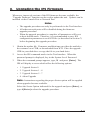
3.1.2. Connect your PC to the IPS
The IPS can either be controlled by a local PC, that communicates with
the unit via cable, controlled via external modem, or controlled via TCP/IP
network. In order to switch plugs or select parameters, commands are issued
to the IPS via either the Network Port or Console Port. Note that it is not
necessary to connect to both the Network and Console Ports, and that the
Console Port can be connected to either a local PC or External Modem.
• Network Port: Connect your 10Base-T or 100Base-T network interface
to the IPS Network port.
• Console Port: Use the supplied null modem cable to connect your PC
COM port to the IPS COM (RS232) Port.
• External Modem: Use a standard AT to Modem cable to connect your
external modem to the IPS COM (RS232) Port.
Note that when the IPS is shipped from the factory, RS232 Port Parameters
are set as follows: 9600 bps, 8 Data Bits, One Stop Bit, No Parity. Although
the IPS allows these parameters to be easily redefined, for the purpose
of this Quick Start procedure, it is recommended that you configure your
communications program to accept these default parameters.
3.2 Communicating with the IPS
The IPS offers two separate user interfaces: the Web Browser Interface and the
Text Interface. The Web Browser interface allows you to contact the IPS via
a TCP/IP network, using a standard, JavaScript enabled web browser (such as
Internet Explorer.) The Text Interface consists of a series of ASCII text menus,
which may be accessed via TCP/IP network, Local PC or modem.
Note: The IPS features a default IP Address (192.168.168.168) and
a default Subnet Mask (255.255.255.0). This allows initial network
access without first setting up the unit’s network parameters (providing
that you are contacting the IPS from a node on the same subnet.) When
attempting to access the IPS from a node that is not on the same subnet,
please refer to the User’s Guide for further configuration instructions.
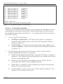
1. Access the Command Mode: This procedure differs slightly, depending
on whether you’re contacting the IPS via the Web Browser Interface or
Text Interface.
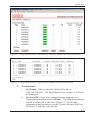
a) Web Browser Interface: Start your JavaScript enabled Web
Browser. Enter the IPS’s default IP address (192.168.168.168)
in your browser address bar and then press [Enter]. A password
prompt will be displayed. Since at this point, the user name and
password have not yet been defined, you can simply click OK
without keying in a user name or password. The Plug Status Screen
will be displayed as shown in Figure 3.1.

3-3
Quick Start
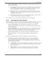
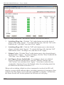
Figure 3.1: Plug Status Screen - Web Browser Interface (Model IPS-800-D20 Shown)
Internet Power Switch v1.41h Site ID: (undefined)
Plug | Name | Password | Status | Boot/Seq. Delay | Default |
-----+------------------+-------------+--------+-----------------+---------+
1 | (undefined) | (undefined) | ON | 0.5 Secs | ON |
2 | (undefined) | (undefined) | ON | 0.5 Secs | ON |
3 | (undefined) | (undefined) | ON | 0.5 Secs | ON |
4 | (undefined) | (undefined) | ON | 0.5 Secs | ON |
5 | (undefined) | (undefined) | ON | 0.5 Secs | ON |
6 | (undefined) | (undefined) | ON | 0.5 Secs | ON |
7 | (undefined) | (undefined) | ON | 0.5 Secs | ON |
8 | (undefined) | (undefined) | ON | 0.5 Secs | ON |
-----+------------------+-------------+--------+-----------------+---------+
“/H” for help.
IPS>
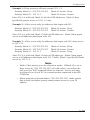
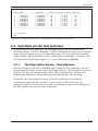
Figure 3.2: Plug Status Screen - Text Interface (Model IPS-800-D20 Shown)
b) Text Interface:
i. Via Telnet: Telnet to the IPS’s default IP address
(192.168.168.168). The Plug Status Screen (Figure 3.2) should
be displayed.
ii. Via Local PC: Start your communications program (e.g.,
Hyperterminal) and then press [Enter]. The Plug Status Screen
should be displayed as shown in Figure 3.2. The default
communications parameters for the Console Port are 9600 bps,
No Parity, 8 data bits, One stop bit.

3-4
IPS-800/1600-D20 Series - User’s Guide
iii. Via Modem: Use your communications program to dial the
number for the phone line which is connected to your external
modem. The Plug Status Screen should be displayed as shown
in Figure 3.2. Note that in order to communicate with the
unit via modem, you must first access the command mode via
Network or Local PC, and use the Serial Parameters Menu to
set the Port Mode to "Modem."
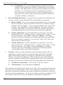
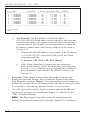
2. Test Switching Functions: You may wish to perform the following tests
in order to make certain that the IPS is responding to commands.
a) Reboot Outlet: If you are communicating with the unit via the Web
Browser Interface, select the button in the "Boot" column for Plug 1,
and then click on "Apply." If you are operating the unit via the Text
interface, type /BOOT 1 and press [Enter]. The status indicator
for Plug 1 should go off, pause for a moment, and then go back on,
indicating that the boot cycle has been successfully completed.
b) Switch Outlet Off: From the Web Browser Interface, select the
button in the "Off" column for Plug 1, and then click "Apply." From
the Text Interface, type
/OFF 1 and press [Enter]. The status
indicator for Plug 1 should go Off, indicating that the command has
been successfully completed. Leave Plug 1 in the "Off" state, and
then proceed to the next step.
c) Switch Outlet On: From the Web Browser Interface, select the
button in the "On" column for Plug 1, and then click "Apply." From
the Text Interface, type
/ON 1 and press [Enter]. The status
indicator for Plug 1 should then go back On, indicating that the
command has been successfully completed.
3. Log Out: When you have finished communicating with the unit it is
important to always log off by issuing the appropriate IPS command,
rather than simply closing your Telnet or communications program.
When you log off using the proper IPS command, this ensures that the
unit has completely exited from command mode, and is not waiting for
the inactivity timeout to elapse before allowing additional connections.
a) Web Browser Interface: Click on the "Log Out" button.
b) Text Interface: Type /X and press [Enter].
This completes the Quick Start Guide for the IPS. Prior to placing the unit into
operation, it is recommended to refer to the remainder of this User’s Guide for
important information regarding advanced configuration capabilities and more
detailed operation instructions. If you have further questions regarding the IPS
unit, please contact WTI Customer Support as described in Appendix C.

4-1
4. Installation
This Section provides further details regarding installation of the IPS unit.
4.1. Power Supply Connection
Connect the IPS unit to an appropriate power supply. Note that the IPS’s Main
Power switch must be "On" in order for the unit to operate.
CAUTIONS:
• Before attempting to install this unit, please review the warnings
and cautions listed at the front of the user's guide.
• This device should only be operated with the type of power
source indicated on the instrument nameplate. If you are not
sure of the type of power service available, please contact your
local power company.
• Reliable earthing (grounding) of this unit must be maintained.
Particular attention should be given to supply connections when
connecting to power strips, rather than directly to the branch
circuit.
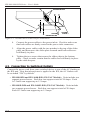
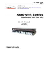
4.1.1. Installing the Cable Keepers
The IPS includes cable keepers, which are designed to prevent the power
supply cables from being accidentally disconnected from the unit.
• IPS-1600-D20 and IPS-1600E-D20: Sixteen-plug units include pre-
installed cable keepers. When attaching the power supply cables to the
unit, first swing the cable keepers out of the way, then plug the power
cables securely into the power inputs. When the cables are in place, snap
the cable keepers over each plug to secure the cables to the unit.
• IPS-800-D20 and IPS-800E-D20: The cable keeper for eight-plug units
must be installed by the user.
1. First make certain that
both of the IPS's two power cables are
disconnected from the power source.
2. Use the screws supplied with the cable keeper kit to attach the
bottom plate to the underside of the IPS-800 unit as shown in
Figure 4.1. When properly attached, the bottom plate will protrude
about one inch beyond the edge of the IPS-800 unit.
3. Use the screws supplied with the cable keeper kit to loosely attach
the slider plate to the bottom plate as shown in Figure 4.1. Make
certain that the slider plate moves freely, ensuring that it can be
easily moved into position once the power cables are in place.

4-2
IPS-800/1600-D20 Series - User’s Guide
4. Connect the power cables to the power inlets. Check to make sure
that both cables are firmly seated in the power inlet connectors.
5. Align the power cables with the two notches in the top of the slider
plate, and then move the slider plate forward until both cables are
held firmly in place.
6. Tighten the two screws that secure the slider plate to the bottom
plate. Check to make certain that the cables are held firmly in place
by the cable keepers.
4.2. Connection to Switched Outlets
Connect the power cord from your switched device to one of the AC Outlets on
the IPS unit. Note that when power is applied to the IPS, the AC Outlets will
be switched "ON" by default.
• IPS-800-D20 and IPS-1600-D20 (120 VAC Models): Units include two
separate power busses. Each bus can support a total of 20 Amps. Each
AC Outlet can support up to 15 Amps.
• IPS-800E-D20 and IPS-1600E-D20 (230 VAC Models): Units include
two separate power busses. Each bus can support a total of 20 Amps.
Each AC Outlet can support up to 15 Amps.
IPS UNIT
POWER INLETS
BOTTOM
PLATE
SLIDER
PLATE
SCREW
RECEPTACLES
Figure 4.1: IPS-800 Series Cable Keeper Installation

4-3
Installation
4.3. Serial COM / RS232 Port Connection
The COM Port is a male, RS232C DB9 connector, wired in a DTE
configuration. In the default state, the COM port is configured for 9600
bps, no parity, 8 data bits, 1 stop bit. The COM Port can be connected to
either an external modem or a local PC, but not both items at the same time.
Appendix A describes the COM Port interface.
4.3.1. Connecting a Local PC
Use the supplied null modem cable to connect your PC COM port to the IPS
COM (RS232 Port.) Make certain that the Serial Port Mode is set to "Console"
as described in Section 5.3.1.
4.3.2. Connecting an External Modem
When connecting directly to an external modem, use a standard AT to
Modem cable. Make certain that the modem is initialized at the same default
parameters as the IPS COM Port. Make certain that the IPS Serial Port Mode
is set to "Modem" as described in Section 5.3.1.
4.4. Connecting the Network Cable
The Network Port is an RJ45 Ethernet jack, for connection to a TCP/IP
network. Connect your 10Base-T cable to the Network Port. Note that the
IPS includes a default IP address (192.168.168.168) and a default subnet mask
(255.255.255.0.) When installing the IPS in a working network environment,
it is recommended to define network parameters as described in Section 5.3.4.
Note: The IPS features a 10Base-T Interface. When connecting to a
100Base-T interface, most router switches will autosense to determine
if the device is 100Base-T or 10Base-T, and then configure the network
interface accordingly. If your router switch does not autosense, the
network interface port must be manually set to 10Base-T.
This completes the IPS installation instructions. Please proceed to the next
Section for instructions regarding unit configuration.

4-4
IPS-800/1600-D20 Series - User’s Guide

5-1
5. Configuration
5.1. System Mode and User Mode
In order to restrict access to sensitive command functions, the IPS features two
operating modes; System Mode and User Mode.
• System Mode: Allows access to all configuration menus, switching
functions and status screens. The System Mode Status Screens show
On/Off conditions for all switched outlets, and lists all currently defined
system parameters.
• User Mode: Allows access to switching and reboot commands, but
does not allow access to configuration functions. Users may only issue
commands to, or view status of the plugs that are specifically allowed by
their password.
The IPS will display a password prompt when the unit is contacted via the
COM Port or Network Port. The password entered at this prompt determines
whether the unit will start-up in System Mode or User Mode. If the System
Password is entered, the System Mode will be active. If a Plug Password is
entered, the User Mode will be active. The System Password is defined via the
General Parameters menu (Section 5.3.1), and the Plug Passwords are defined
via the Plug Parameters Menus (Section 5.3.3.)
Notes:
• If you wish to restrict access to configuration menus, you must
define the System Password.
• If the System Password is not defined, the IPS will always start-up
in System Mode, allowing unprotected access to configuration and
switching functions.
• If the System Password is not defined, the Password Prompt will not
be displayed when you access the IPS via the Text Interface. The
prompt will always be displayed when the IPS is contacted via the
Web Browser Interface.
• When the IPS is contacted via Network, the password prompt will
also include a field for the user name. If you have not defined a user
name, then you may leave this field blank, and only the password
is required to gain access to the unit. The user name prompt is not
displayed when the unit is contacted via the Text Interface.

5-2
IPS-800/1600-D20 Series - User’s Guide
5.2. Communicating with the IPS
In order to configure the unit or invoke command functions, you must first
connect to the IPS and access command mode. As discussed in Section 3, the
IPS offers two separate command interfaces: the Web Browser Interface, and
the Text Interface.
The IPS also offers three different methods for accessing command mode; via
network, via external modem, or via local PC. The Web Browser Interface is
only available when the IPS is contacted via network, and the Text Interface is
available via network, modem or local PC. The sections that follow describe
the procedure for accessing the Web Browser Interface or the Text Interface.
Note: Configuration functions are only available when you have
logged into the IPS command mode using the System Password.
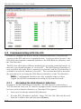
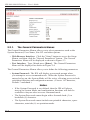
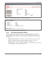
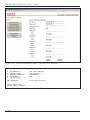
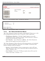
5.2.1. Accessing the Web Browser Interface
In order to use the Web Browser Interface, the IPS must be connected to a
TCP/IP network, and your PC must be equipped with a JavaScript enabled web
browser (such as Internet Explorer or Netscape® Navigator.)
1. Start your JavaScript enabled Web Browser.
2. Key the IPS’s IP address (default = http://192.168.168.168) into the web
browser’s address bar, and then press
[Enter].
Figure 5.1: Plug Status Screen - Web Browser Interface (IPS-800-D20 Shown)
Page is loading ...
Page is loading ...
Page is loading ...
Page is loading ...
Page is loading ...
Page is loading ...
Page is loading ...
Page is loading ...
Page is loading ...
Page is loading ...
Page is loading ...
Page is loading ...
Page is loading ...
Page is loading ...
Page is loading ...
Page is loading ...
Page is loading ...
Page is loading ...
Page is loading ...
Page is loading ...
Page is loading ...
Page is loading ...
Page is loading ...
Page is loading ...
Page is loading ...
Page is loading ...
Page is loading ...
Page is loading ...
Page is loading ...
Page is loading ...
Page is loading ...
Page is loading ...
Page is loading ...
Page is loading ...
Page is loading ...
Page is loading ...
Page is loading ...
Page is loading ...
-
 1
1
-
 2
2
-
 3
3
-
 4
4
-
 5
5
-
 6
6
-
 7
7
-
 8
8
-
 9
9
-
 10
10
-
 11
11
-
 12
12
-
 13
13
-
 14
14
-
 15
15
-
 16
16
-
 17
17
-
 18
18
-
 19
19
-
 20
20
-
 21
21
-
 22
22
-
 23
23
-
 24
24
-
 25
25
-
 26
26
-
 27
27
-
 28
28
-
 29
29
-
 30
30
-
 31
31
-
 32
32
-
 33
33
-
 34
34
-
 35
35
-
 36
36
-
 37
37
-
 38
38
-
 39
39
-
 40
40
-
 41
41
-
 42
42
-
 43
43
-
 44
44
-
 45
45
-
 46
46
-
 47
47
-
 48
48
-
 49
49
-
 50
50
-
 51
51
-
 52
52
-
 53
53
-
 54
54
-
 55
55
-
 56
56
-
 57
57
-
 58
58


Western Telematic IPS-1600-D20 User manual
- Category
- Networking
- Type
- User manual
- This manual is also suitable for
Ask a question and I''ll find the answer in the document
Finding information in a document is now easier with AI
Related papers
-
WTI IPS-400-CE User manual
-
-
Western Telematic IPS-800, IPS-800-CE, IPS-1600, IPS-1600CE User manual
-
 Western Telematic NBB-1600-D20, NBB-1600E-D20, NBB-1600CE-D16 User manual
-
 Western Telematic Switch CMS-16 User manual
-
 Western Telematic AFS-16-1 User manual
-
 Western Telematic APS-16 User manual
-
 Western Telematic PTS-8NE15-1 User manual
-
 Western Telematic APS-8 User manual
-
 Western Telematic RPC-4840N User manual


Other documents
-
Black Box SWI082 User manual
-
-
-
-
-
Runco DTV-873 User manual
-
-
-
 I-Tech Company Network Card CMS 6R4 Series User manual
-
 RDC Reporter D20 Operating Information & Installation Instructions

