Page is loading ...

British Gas Tested and Certified
G. C. No. 47 116 01
This boiler is for use with natural gas only
LEAVE THESE INSTRUCTIONS
ADJACENT TO THE GAS METER
BIASI U.K. Ltd
Unit 41, Planetary Road Industrial Estate, Neachells Lane
Willenhall, Wolverhampton WV13 3XB
Telephone: 01902 304400 --- Fax: 01902 304321
WALL HUNG FAN FLUE
ROOM SEALED GAS COMBINATION BOILER
MODEL

TABLE OF CONTENTS
boiler 20/1 MFS
sect. subject page No.
1 General information 1. . . . . . . . . . . . . . . . . .
1.1 Overall view 1. . . . . . . . . . . . . . . . . . . . . . . . . . .
1.2 Technical data 2. . . . . . . . . . . . . . . . . . . . . . . . .
1.3 Description 3. . . . . . . . . . . . . . . . . . . . . . . . . . .
1.4 Flue pipes optional extras 3. . . . . . . . . . . . . .
1.5 Design principles and operating sequence 4
2 General requirements 6. . . . . . . . . . . . . . . . .
2.1 Related documents 6. . . . . . . . . . . . . . . . . . . .
2.2 Location of appliance 6. . . . . . . . . . . . . . . . . .
2.3 Flue system 6. . . . . . . . . . . . . . . . . . . . . . . . . . .
2.4 Gas supply 6. . . .. . . . .. . . . .. . . . .. . . . .. . .
2.5 Air supply 7. . . . . . . . . . . . . . . . . . . . . . . . . . . .
2.6 Water circulation (central heating) 7. . . . . . .
2.7 Domestic water 8. . . . . . . . . . . . . . . . . . . . . . .
2.8 Electrical supply 8. . . . . . . . . . . . . . . . . . . . . . .
3 Installation 9. . . . . . . . . . . . . . . . . . . . . . . . . . .
3.1 Delivery 9. . . . . . . . . . . . . . . . . . . . . . . . . . . . . .
3.2 Measurements for installing the appliance 9
3.3 Assembling the wall mounting bracket 10. . .
3.4 Drilling the hole for the flue 10. . . . . . . . . . . . .
3.5 Unpacking the boiler 11. . . . . . . . . . . . . . . . . . .
3.6 Mounting the boiler on the bracket 12. . . . . . .
3.7 Mounting the flue exhaust pipes 13. . . . . . . . .
3.8 Flue terminal guard 15. . . . . . . . . . . . . . . . . . . .
3.9 Electrical connections 15. . . . . . . . . .. . . . .. . .
4 Commissioning 17. . . . . . . . . . . . . . . . . . . . . . .
4.1 Electrical installation 17. . . . . . . . . . . . . . . . . . .
4.2 Gas supply installation 17. . . . . . . . . . . . . . . . .
4.3 Filling the d.h.w. system 17. . . . . . . . . . . . . . . .
4.4 Initial filling of the system 17. . . . . . . . . . . . . . .
4.5 Setting the system pressure 18. . . . . . . . . . . .
4.6 Lighting the boiler 18. . . . . . . . . . . . . . . . . . . . .
4.7 Checking the gas pressure at the burner 19.
4.8 Checking the flue system 20. . . . . . . . . . . . . . .
4.9 Checking the full sequence control 20. . . . . .
4.10 Testing the d.h.w. system flow 20. . . . . . . . . . .
4.11 Selecting the pump operating modes 20. . . .
4.12 Instructing the user 21. . . . . . . . . . . . . . . . . . . .
5 Maintenance 22. . . . . . . . . . . . . . . . . . . . . . . . .
5.1 General 22. . . . . . . . . . . . . . . . . . . . . . . . . . . . . .
5.2 Recommended routine maintenance 22. . . . .
6 Servicing instructions 23. . . . . . . . . . . . . . . . .
6.1 Replacement of parts 23. . . . . . . . . . . . . . . . . .
6.2 To gain general access 23. .. . . . .. . . . .. . . . .
6.3 To drain the main circuit of the boiler 24. . . . .
6.4 To drain the d.h.w. circuit of the boiler 25. . . .
6.5 Setting gas pressures 25. . . . . . . . . . . . . . . . . .
6.6 Reducing the maximum output to meet
the central heating power requirements 25. .
6.7 Electronic regulation p.c.b. 26. . . . . . . . . . . . .
6.8 Full sequence control p.c.b. 26. . . . . . . . . . . .
6.9 Overheat thermostat 27. . . . . . . . . . . . . . . . . . .
6.10 Burner 27. . . . . . . . . . . . . . . . . . . . . . . . . . . . . ..
6.11 Injectors 28. . . . . . . . . . . . . . . . . . . . . . . . . . . . . .
6.12 Ignition and/or detection electrodes 28. . . . . .
6.13 Insulation panels 28. . . . . . . . . . . . . . . . . . . . . .
6.14 Gas modulator cartridge 28. . . . . . . . . . . . . . . .
6.15 On---off operator coils 29. . . . . . . . . . . . . . . . . .
6.16 Gas modulator coil 29. . . . . . . . . . . . . . . . . . . .
6.17 Gas valve 30. . . . . . . . . . . . . . . . . . . . . . . . . . . . .
6.18 Fan and venturi device 30. . . . . . . . . . . . . . . . .
6.19 Air pressure switch 31. . . . . . . . . . . . . . . . . . . .
6.20 Main heat exchanger 31. . . . . . . . . . . . . . . . . . .
6.21 Main circuit temperature probe 31. . . . . . . . . .
6.22 Pump 31. . . . . . . . . . . . . . . . . . . . . . . . . . . . . .. .
6.23 Main circuit flow switch 32.. . . . . . . . . . . . . . . .
6.24 Pump pressure switch 32. . . . . . . . . . . . . . . . .
6.25 Temperature---pressure gauge 33. . . . . . . . . .
6.26 By---pass 33. . . . . . . . . . . . . . . . . . . . . . . . . . . . .
6.27 Automatic air release valve 33. . . . . . . . . . .. .
6.28 Expansion vessel 33. . . . . . . . . . . . . . . . . . . . . .
6.29 Safety valve 34. . . . . . . . . . . . . . . . . . . . . . . . . . .
6.30 3---way valve 34. . . . . . . . . . . . . . . . . . . . . . . . . .
6.31 D.h.w. heat exchanger 35. . . . . . . . . . . . . . . . .
6.32 D.h.w. temperature probe 37. . . . . . . . . . . . . . .
6.33 D.h.w. flow switch 37. . . . . . . . . . . . . . . . . . . . .
6.34 Water unit 38. . .. . . . .. . . . .. . . . .. . . . .. . . . .
6.35 O---rings position on the d.h.w. heat exch. 40
7 Fault finding 41. . . . . . . . . . . . . . . . . . . . . . . . . .
7.1 Fault finding diagrams 41. . . . . . . . . . . . . .. . .
7.2 Using the fault finding diagrams 41. . . . . . . . .
7.3 Special defects 41. . . . . . . . . . . . . . . . . . . . . . . .
7.4 Water leaks 41. . . . . . . . . . . . . . . . . . . . . . . . . . .
7.5 Difficulty in lighting the burner 41. . . . . . . . . . .
7.6 Incorrect combustion 41. . . . . . . . . . . . . . . . . .
7.7 Traces of gas or exhaust flues 41. . . . . . . . . . .
7.8 Appliance completely shut down 42. . . . . . . .
7.9 Fault of full sequence control p.c.b. 44. . . . . .
7.10 Fault on d.h.w. --- c.h. switching 46. . . . . . . . .
7.11 Fault on modulation 48. . . . . . . . . . . . . . . . . . . .
8 Electric diagrams 50. . . . . . . . . . . . . . . . . . . . .
8.1 General wiring layout 50. . . . . . . . . . . . . . . . . .
8.2 Functional flow diagrams 51. . . . . . . .. . . . .. .
9 Short spare parts list 56. . . . . . . . . . . . . . . . .

1 GENERAL INFORMATION
1
rev. 17.09.93
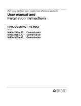
1.1 Overall view
22
1
2
3
4
12
7
34
8
15
(16)
(17)
9
10
11
21
14
23
Front view Rear view
36
26
35
33
30 282932 31
20
2524
18
5
19
13
6
27
1 Main heat exchanger
2 Manual vent cock
3 Combustion chamber
4 Burner
5 Overheat thermostat (probe)
6 Detection electrode
7 Main circuit flow switch
8 Main circuit temperature probe
9 Thermometer probe
10 Pump
11 Pump plug
12 D.h.w. flow switch
13 Pressuretestpointformeasuringoutletpressureat
the gas valve
14 Pressure test point for measuring inlet pressure at
the gas valve
15 Control panel
16 Electronic regulation p.c.b.*
17 Full sequence control p.c.b.*
18 Wiring diagram
19 Gas valve
20 Gas modulator
21 Ignition electrode
22 Fan
23 Venturi device
24 Flue gas sampling point
25 Air pressure switch
26 Expansion vessel
27 Data badge
28 Gas inlet
29 Central heating (c.h.) water return
30 C.h. water flow
31 Domestic hot water (d.h.w.) inlet
32 D.h.w. outlet
33 3---way valve
34 D.h.w. heat exchanger
35 D.h.w. temperature probe
36 Automatic air release valve
37 Safety valve
38 Divertor on 3---way valve
39 Injector
40 Pump pressure switch
41 D.h.w. filter
42 D.h.w. flow limiter
43 By---pass
44 Main circuit drainage cock
45 D.h.w. circuit drainage cock
46 Air intake
47 Flue outlet
* component enclosed in the control panel.

General information
2
rev. 17.09.93
1.2 Technical data
Heat input:
max 28,74 kW 98 080 Btu/h
min 12,40 kW 42 317 Btu/h
Heat output:
max 23.25 kW 79 344 Btu/h
min 8,71 kW 29 274 Btu/h
Central heating
Operating temperature:
max 85 °C
min 35 °C
Working pressure
max 3 bar 43,5 p.s.i.
Water content 6,25 lts. 1,37 gals.
Built in expansion vessel:
Total capacity 7,5 lts. 1,65 gals.
Pre---charge pressure 0,7 bar 10,1 p.s.i.
Available head at 1000 litres/hr (220 gals/hr)
3,2 m w.g. 126 ins w.g.
Temp. difference for
flow and return
20 °C
Flow rate of water
through the appliance
1 000 lts./h 220 gals./h
Max permissible coldwater capacity withoutadditional
expansion vessel*
71 lts. 15,6 gals.
Domestic hot water
Operating temperature:
max 65 °C
min 37 °C
Working pressure:
max 10 bar 145 p.s.i.
min 0,2 bar 2,9 p.s.i.
Water content 0,38/lts. 0,08 gals.
flow rate:
min 2,0 lts./min 0,4 gals./min
30 °C rise 11,1 lts./min 2,4 gals./min
35 °C rise 9,5 lts./min 2,0 gals./min
40 °C rise 8,3 lts./min 1,8 gals./min
Gas requirements
max gas rate 2,79 m
3
/h 98,5 ft
3
/h
min gas rate 1,04 m
3
/h 36,7 ft
3
/h
Inlet pressure 20 mbar 7,9 in w.g.
Burner pressure:
max 9,7 mbar 3,9 in w.g.
min 1,4 mbar 0,6 in w.g.
Burner injectors 12 x 1.35
Component details
Gas control valve SIT 827 nova
Burner Polidoro
Electrical data
Electrical supply 240 V~
Frequency 50 Hz
Power consumption 150 W
External fuse rating 3 A
Internal fuse rating F1 0,08 A T**
Internal fuse rating F2 1,6 A T**
Connections
Gas connection 15 mm o.d.
c.h. flow 22 mm o.d.
c.h. return 22 mm o.d.
D.h.w. inlet 15 mm o.d.
D.h.w. outlet 15 mm o.d.
Safety discharge pipe 15 mm o.d.
Flue pipes specifications
Outer diameters:
flue exhaust pipe 60 mm 2,36 ins
Air intake pipe 100 mm 3,93 ins
Standard length 850 mm 33,46 ins
Maximum length *** 3 000 mm 118,11 ins
Other specifications
Height 967 mm 38,1 ins
Width 400 mm 15,7 ins
Depth 370 mm 14,5 ins
Dry weight 50 kg 110 lb
* If required an external expansion vessel can be fitted
** Spare fuses are available in housing of the electronic regulation p.c.b.
*** Using one or more horizontally elongated flue pipes kit (see sect. 1.4).

General information
3
rev. 17.09.93
0.0
0.5
1.0
1.5
2.0
2.5
3.0
3.5
4.0
4.5
0 100 200 300 400 500 600 700 800 900 1000 1100 1200 1300 1400 1500
14,8
4,4 5,13,62,92,21,50,70
lts./h
gals./min5,54,74,03,32,51,81,10,4
13,1
11,5
9,8
8,2
6,6
4,9
3,3
1,6
0
441,1
392,4
343,4
294,3
245,2
196,2
147,1
98,1
49,3
0
mbar ft. head
m w.g.
fig. 1.1
Available pump head
The curve in fig. 1.1 shows the water pressure (head)
available to the central heating (c.h.) circuit as a func-
tion of flow; the load loss of the appliance has already
been subtracted.
1.3 Description
7
22
3
1
4
2
13
10
37
12
19
14
36
23
33
26
34
25
38
43
41
44
42
30
46
31
47
2928 32
39
45
24
40
fig. 1.2
The boiler 20/1 MFS is a combined central heating
(c.h.) and domestic hot water (d.h.w.) appliance.
It is produced as a room sealed category appliance
suitable for wall mounting applications only.
This boiler is suitable only for sealed systems.
It incorporates:
--- full sequence electronic ignition system
--- fan powered flue outlet with an annular co---axial
combustionairintakewhichcanberotatedthrough
360 degrees
--- circulating pump
--- expansion vessel
--- temperature and pressure gauge
--- safety valve
--- 3---way valve
1.4 Flue pipes optional extras
The following items are available.
The respective mounting instructions are included in
the carton containing the parts of the kit.
Horizontally elongated flue pipes
fig. 1.3
Morethanone sectionmaybeused butthe totallength
of the exhaust duct must not exceed 3 m (9,84 ft).
Every section allows to extend the duct by 825 mm
(32,48 ins).

General information
4
rev. 17.09.93
Supplementary elbow
fig. 1.4
Asinglesupplementaryelbowonly, canbeusedduring
installation: the length of the exhaust duct (standard
elbow + the supplementary elbow included) must not
exceed1800 mm (5,9 ft).
Vertically elongated flue pipes
fig. 1.5
The kit marked vertically elongated flue pipes allowsto
rise the axis of the horizontal part of the exhaust duct.
1.5 Design principles and operating
sequence
Water system design
The basic purpose of a boiler is to generate heat
through the combustion of gas and to direct the heat
through a water circuit, as required.
A combination---type appliance allows the heat to be
usedeitherfor heatingthe environmentand forheating
hot water for domestic use.
Main water circuit
This is an internal water circuit in the appliance which
passes through the main heat exchanger and absorbs
heat directlyfrom the combustion of gas. The water in
thiscircuit isthe same as thewater thatis circulatedby
the pump and flows through the c.h. system.
The path of the water in the main water circuit can be
changed by a 3---way valve.The main water circuit is
connected to the c.h. circuit during operation with the
c.h. system (see fig. 1.6).
Main heat exchanger
Main circuit
By---pass
Pump
C.h. circuit
flow switch
fig. 1.6
During operation as a d.h.w. heater, themain water cir-
cuit is directed throughthe d.h.w. heat exchanger(see
fig. 1.7).
Main heat exchanger
Flow switch
By---pass
Pump
D.h.w. heat
exchanger
D.h.w flow
switch
fig. 1.7
Also, a by---pass valveis installedin themain water cir-
cuit. The by---pass valve assures an adequate water
flow through the main heat exchanger regardless of
water flow conditions inthe water circuit, thus avoiding
damage due to temperature variations.
Safety devices
Inbothc.h.andd.h.w.modessafeoperatingisensured
by a pump pressure switch and a flow switch on main
water circuit.
Ifthepressureinthemainwatercircuitisinsufficientthe
pump pressure switch disconnects the supply to the
pump.
Iftheflowrate inthe mainwater circuitis insufficientthe
flow switch on main water circuit disconnects the sup-
ply to the full sequence control p.c.b.
In both cases the boiler is stopped in order to prevent
damages.
A overheat thermostat disconnects the two ON---OFF
operators on the gas valve; as a result, the burner is
shutdownand theshut-downwarninglightwillappear.
A safety valve is provided to relieve excess pressure
from the main circuit.
Theapplianceisequippedwithasafetysystem(venturi
deviceandairpressureswitch)whichsensestheveloc-
ity of the exhaust flues. If the air pressure switch does

General information
5
rev. 17.09.93
not sense the correct velocity, the burner will shut
down.
Operating sequence on central heating mode
The function switch must be set on position.
The water in the main circuit is sent to the c.h. system
whenthe3---wayvalveisinthec.h.position. Inthiscon-
figuration, the divertor is in the upper position and the
d.h.w. heat exchanger circuit is cut out.
Theapplianceiscontrolledbyanelectronicthermostat;
water deliverytemperature canbe adjustedfrom 35°C
to 85 °C.
When heat is requested, a command reaches the full
sequence control p.c.b.; this command starts the fan,
which switches the air pressure switch. After the air
pressure switch has been switched, the combustion
chamberispurgedofanyresidualunburnedgassesfor
a few seconds. Next , the lighting cycle begins with a
spark from the ignition electrode; at the same time,
electricalpowerisfedtothetwoON---OFFoperatorson
the gas valve.
If the flame detection electrode does not sense the
flamewithin4 secondsfromthe beginningof thecycle,
the full sequence control p.c.b. interrupts the lighting
cycle,the electricspark is shut off and thepower isdis-
connectedfromthetwoON---OFFoperatorsonthegas
valve; as a result, the burner is shut down.
At this point, the shut down warning light appears and
the reset push---button must be pressed to restart the
lighting cycle.
If the detection electrode senses flames within 4 sec-
ondsfrom the beginning of the cycle, the full sequence
control p.c.b. interrupts the electric sparks and holds
the burner alight.
At the same time, the temperature of the heatingcircuit
ismeasuredby themain circuittemperature probeand
this temperature is compared with the value set on the
c.h. temperature adjustment ( ).
After lighting has been accomplished, the amount of
flow from the gas valve is determined by the electronic
regulation p.c.b.:
--- when the temperature of the c.h. water is less than
thepresettemperature bya?tvalue(differencebe-
tweenoutputand inputtemperature)between 6°C
and 15 °C, the appliancewillsupply heating power
which ranges from 35 to 100% of its maximum ca-
pacity;
--- when the temperature of the c.h.water is less than
the preset temperature by a ?t value which is less
than 6 °C, the appliance will supply its minimum
heating power (35% of its maximum heating
power);
--- if the minimum power is greater than the heat
emitted from the radiators, the burner will shut
down.
Heating power can be varied from 35 to 100% of the
maximum rated power.
Operating sequence on d.h.w. mode
Wheneverad.h.w.tapisopened,thed.h.w.flowswitch
onthe d.h.w. system is activated and a signalis sentto
the electronic regulation p.c.b. This signal moves the
shutter on the 3---way valve and thus closes the c.h.
water circuit and opens the d.h.w. heat exchanger cir-
cuit.
The burner willoperateatnominalpower, orat apower
rating which keeps d.h.w. at the constant temperature
desired(aslongasthedemandforheatingpowerdoes
not exceed the nominal power supplied by the boiler).
Thus, burner operation depends on the amount of
d.h.w.usedandthetemperaturewhichhasbeenseton
the d.h.w. temperature adjustment ( ).
D.h.w. only operation
Whenthefunctionswitchisseton position,thec.h.
adjustment system is deactivated, the 3---way valve is
nolonger actuated, theshutter closeswater deliveryto
the c.h. circuitand opensdeliveryto thed.h.w. heat ex-
changer. Whend.h.w. iswithdrawnfromthed.h.w.sys-
tem, operation of the appliance will be the same as
operation with the function switch set on position.

2 GENERAL REQUIREMENTS
6
rev. 17.09.93
This appliance must be installed by a competent
person in accordance with the Gas Safety (installa-
tion & Use) Regulations 1984.
2.1 Related documents
Theinstallationofthisappliancemustbeinaccordance
withtherelevantrequirementsoftheGasSafety(Instal-
lation & Use) Regulations (1984), the Local Building
Regulations, the current I.E.E. Wiring Regulations, the
by---laws of the local water undertaking, and in Scot-
land, inaccordancewith the Building Standards (Scot-
land) Regulation. Health and safety document n° 635
”Electricity at work regs. 1989”.
It should be in accordance also with the following Brit-
ish Standard Codes of Practice:
Low pressure installa-
tion pipes
BS 6891 1988
Boilers of rated input
not exceeding 60 kW
BS 6798 1987
Forced circulation hot
water systems
BS 5449 1990
Installation of gas hot
water supplies for do-
mestic purposes
(2
nd
family gases)
BS 5546 1990
Flues BS 5540---1 1990
Air supply BS 5540---2 1989
2.2 Location of appliance
The appliance may be installed in any room or internal
space, although particular attention is drawn to the re-
quirements of the current I.E.E. Wiring Regulations,
andinScotland,theelectricalprovisionsoftheBuilding
Regulations applicable in Scotland, with respect to the
installation of the combined appliance in a room con-
taining a bath or shower.
Where a room--sealed appliance is installed in a
room containing a bath or shower, any electrical
switchor appliance control, utilising mainselectric-
ity should be so situated that it cannot be touched
by a person using the bath or shower.
Thelocationmust permitan adequatespace forservic-
ing and air circulation around the appliance
(see fig. 2.1).
a
b
c
d
a
b
c
d
155 mm
130 mm
500 mm
50 mm
6,1 ins
5,1 ins
19,7 ins
1,9 ins
fig. 2.1
The location must permit the provision of an adequate
flue and termination.
For unusual locations special procedures may be
necessaryandBS6798---1987givesdetailedguidance
on this aspect.
A compartmentused to enclosethe appliance mustbe
designed specifically for this purpose.
This appliance is not suitable for external installation.
2.3 Flue system
The provision for satisfactory flue termination must be
made as described in BS 5440---1.
Theappliancemustbeinstalledsothattheflueterminal
is exposed to external air.
It must not be installed so that the terminaldischarges
intoanotherroomorspaceas anouthouseorlean---to.
It is important that the position of the terminal allows a
free passage of air across at all times.
The terminal should be located with due regard for the
damage or discoloration that might occur to building
products in the vicinity.
In cold and/or humid weather water vapour may con-
dense on leaving the flue terminal; the effect of such
”steaming” must be considered.
The minimum acceptable spacing from the terminal to
obstructions and ventilation openings are specified in
fig. 2.2.
A
BC
D
E
F
G
HI
J
KL
F
G
Terminal position mm
A Directly below a open window or other opening 300. . . . . . . .
B Below gutters, solid pipes or drain pipes 75. . . . . . . . . . . . . . .
C Below eaves 200. . . . . . . . . . . . . . . . . . . . . . . . . . . . . . . .. . . . . .
D Below balconies or car port roof 200. . . . . . . . . . . . . . . . . . . . .
E From vertical drain pipes and soil pipes 75. . . . . . . . . . . . . . . .
F From internal or external corners 300. . . . . . . . . . . . . . . . . . . .
G Above ground or below balcony level 300. . . . . . . .. . . . . . . .
H From a surface facing a terminal 600. . . . . . . . . . . . . . . . . . . . .
I From a terminal facing a terminal 1 200. . . . . . . . . . . . . . . . . . .
J From an opening in the car port. . .
(e.g. door, window) into dwelling 1 200. . . . . . . . . . . . . . .
K Vertically from a terminal in the same wall 1 500. . . . . . . . . . .
L Horizontally from a terminal in the same wall 300. . . . . . . . . . .
fig. 2.2
2.4 Gas supply
Gas meter is connected to theservice pipe by the local
gas region or a local gas region contractor.
If the gas supply for the boiler serves other appliances
ensure that an adequate supplyis available both tothe

General requirements
7
rev. 17.09.93
boiler and the other appliance when they are in use at
the same time.
Pipework must be of adequate size. Pipes of a smaller
sizethantheboilerinletconnectionshouldnotbeused.
Installation pipes should be fitted in accordance with
BS 6891---1988andthecompleteinstallationshouldbe
tested for soundness.
2.5 Air supply
The room in which the boiler is installed does not re-
quire a purpose provided air vent.
If installed in a cupboard or compartment, ventilation is
also required for cooling.
Recommendations for air supply are detailed in
BS 5440---2 .
2.6 Water circulation (central heating)
DetailedrecommendationsaregiveninBS6798---1987
and BS 5449---1 1990; thefollowing notes are given for
general guidance.
Pipework
CoppertubingtoBS2871---11977isrecommendedfor
waterpipes. Jointingshouldbeeitherwithcapillarysol-
dered or with compression fittings.
Wherepossiblepipesshouldhaveagradienttoensure
air is carried naturally to air release points and water
flows naturally to drain taps.
The appliance has a built---in automatic air release
valve anyway, it should be ensured as far as possible
that the appliance heat exchanger is not a natural col-
lecting point for air.
Except where providing useful heat, pipes should be
insulated to prevent heat loss and to avoid freezing.
Particular attention should be paid to pipes passing
through ventilated spaces in roofs and under floors.
By--pass
The appliance includes an automatic by---pass valve
which protects the main heat exchanger in case of re-
ducedorinterruptedwatercirculationthroughtheheat-
ing system due to the closing of thermostatic valves or
cock---type valves within the system.
The by---pass iscalibratedtoassure a minimumflow of
500---600 lts/hr through the main heat exchanger.
System design
This boiler is suitable only for sealed systems.
A typical lay---out is illustrated in the following figure.
Gas supply pipe
Drain tap
(at lowest point)
Cold water inlet
Sink
Shower
fig. 2.3

General requirements
8
rev. 17.09.93
Thesemustbelocatedinaccessiblepositionstopermit
the draining of the whole systems. The taps must be
at least 15 mm nominal size and manufactured in ac-
cordance with BS 2870 1980.
Air release points
These must be fitted at all high points where air will
natural collect and must be sited to facilitate complete
fitting of the system.
The appliancehas an integralsealed expansion vessel
to accommodate the increase of water volume when
the system is heated.
It can accept up to 7 lts (1,5 gals.) of expansion water.
If the heating circuit has an unusually high water con-
tent, calculate the total expansion and add additional
sealed expansion vessel with adequate capacity.
Mains water feed: central heating
There must be no directconnection to the mains water
supplyeven througha nonreturn valve,without theap-
proval of the Local Water Authority.
Filling
A method for initially filling the system and replacing
water lost during servicing must be provided and it
must comply with local water authority regulations.
A possible method is shown in fig. 2.4.
C.h. return Cold water inlet
Temporary hose
Wall mounting
bracket
fig. 2.4
The installer should ensure that no leaks exist as fre-
quent fillingof thesystem couldcause prematurescal-
ing of the heat exchanger.
2.7 Domestic water
Thedomesticwatermust beinaccordancewiththerel-
evant recommendations of BS 5546. Copper tubing to
BS 2871---1 is recommended for water carrying pipe-
work and must be use for pipework carrying potable
water.
2.8 Electrical supply
Warning, this appliance must be earthed.
External wiring to the appliance must be carried outby
acompetentpersonandbeinaccordancewiththecur-
rent I.E.E. Regulations and local regulations which
apply.
The boiler 20/1 MFS is supplied for connection to a
240 V~ 50 Hzsupply. The supplymust be fused at 3A.
Themethodofconnectiontotheelectricitysupplymust
facilitate complete electrical isolation of the appliance
bythe useof afused doublepoleisolatorhavingacon-
tact separation of at least 3 mm in all poles or alterna-
tively, by the use of a 3A fused three pin plug and un-
switched shuttered socket outlet both complying with
BS 1363.
Thepointofconnectiontotheelectricitysupplymustbe
readilyaccessibleandadjacenttotheapplianceexcept
were the appliance is installed in a bathroom this must
be sited outside the bathroom.

3 INSTALLATION
9
rev. 17.09.93
3.1 Delivery
There will be 3 items:
1 the boiler fully assembled;
2 the wall mounting bracket with cocks and pipes;
3 Standardflueassemblywhichincludefluepipesand90°elbow.
3.2 Measurements for installing the appliance
a --- safety valve discharge pipe
b --- gas
c --- c.h. water return
d --- c.h. water flow
e --- d.h.w. inlet
252 (9,92)
a b c d e
Front view Top view
187 (7,36) 213 (8,38)
400 (15,7)
853 (33,6)
f
f --- d.h.w. outlet
61 (2,40)
25
(1)
54
(1,12)
49
(1,93)
45
(1,77)
40
(1,57)
145
(5,71)
83 (3,27)
78 (3,07)
122 (4,80)
228 (8,97)
50 130
(5,12)(2)
155 (6,1)500 (19,7)
Clearances required for servicing
All measurements are in millimetres (inches in brackets)
50 130
(5,12)(2)
180 (7)
Wall mounting bracket
Wall mounting bracket

installation
10
rev. 17.09.93
3.3 Assembling the wall mounting bracket
The carton marked wall mounting bracket contains the following:
1 mounting bracket;
2 1/2” cock for d.h.w. inlet;
3 3/4” cocks for c.h. flow and return;
4 1/2” nipples for d.h.w. and safety valve outlet;
5 3/4” gaskets;
6 3/4” nuts for mounting 3/4”cocks and gas pipe;
7 3/4” nipple for c.h. return;
8 ø 15 mm o.d.pipe for safety valve discharge;
9 ø 22 mm o.d. pipe for c.h. return with 3/4” connector nut;
10 ø 22 mm o.d. pipe for c.h. flow with 3/4” connector nut;
11 ø 15 mm o.d.pipes for d.h.w circuit;
12 ø 15 mm o.d.pipe for gas inlet;
13 c.h. return pipe with safety valve connection;
14 safety valve;
15 1/2” nuts for mounting the 1/2” cock and nipple;
16 1/2” gaskets;
17 1/2” connector nuts;
18 15 mm compression fitting cock for gas inlet.
18
2
3
5
6
1
8
11
10
9
12
14
13
15
16
17
7
4
--- Position the mounting bracket on the wall. Use a spirit level to
make sure that the support is level;
--- mark the attachment points through the holes indicated;
--- remove the wall mounting bracket and drill holes in the wall at
the points marked;
--- use screws with wall plugs ø 8 mm to attach the wall mounting
bracket to wall;
1
3.4 Drilling the hole for the flue
--- Drill a hole with a diameter of at least 110 mm (4,33 ins) in the
wall; for correct position see sect. 3.2.
Drill the hole in the direction of the flue exhaust pipe so that the
duct will have a slight downward inclination to the outside;
--- mount the cocksand fittingson thebottomofthe wallmounting
bracket and tighten with the nuts;
--- use the connector nuts to connect the pipes to their respective
cocks.
Be sure to use the correct gaskets when installing the pipes;
--- connect valves and pipes from right to left;
Wall mounting bracket (1)
(top view)
423712
15
5
6
16
17
1113 10

Installation
11
rev. 17.09.93
--- mountthecockforgasinlet(18)andthe3/4”cockforc.h.return
(3). Be sure to use the correct gaskets.
--- mount the pipe for c.h. return (9);
Wall mounting
bracket (1)
(front view)
3
5
18
13
12
9
--- mount the safety valve (14) on the c.h. return pipe (13) with a
1/2” gasket. The valve must be mounted with its outlet towards
the left hand.
--- Mount the 1/2” nipple (4) and the pipe for the safety valve dis-
charge (8) with the correct gaskets as indicated. Connect dis-
charge pipe to enable it to discharge externally at low level;
--- connect cocks to corresponding pipes within the appliance
using the correct washers supplied;
--- completetheinstallationconnectingthe pipestothe otherparts
of the plant. Make water heating and gas connections to the
appliance.
8
17
16
4 14
4
Towards the
safety valve.
13
3.5 Unpacking the boiler
--- Open the side of the carton marked opening side;
--- overturn the carton keeping the flaps open;

installation
12
rev. 17.09.93
--- lift up the carton;
--- rest the boiler on the floor and remove the polystyrene guards.
3.6 Mounting the boiler on the bracket
--- Remove the protection caps from the pipes on the boiler;
--- carefully clean the cocks and connections mounted on the wall
mounting bracket;
--- hang the appliance on the bracket;
--- remove the lower protection plate (sect. 6.2);
--- install connectors on the pipes (use the original gaskets
supplied with the wall mounting bracket);
--- tighten the connectors securely;
--- re---install the lower protection plate.

Installation
13
rev. 17.09.93
3.7 Mounting the flue exhaust pipes
Open the carton marked standard flue exhaust pipes.
It contains the following:
19 flue exhaust pipe with wind---resistant terminal;
20 pipe support
21 self---tapping screws 3,5 x 19 mm;
22 springs for the tightening band;
23 gasket tightening band;
24 gasket which seals the elbow to the flue duct;
25 gasket which seals the elbow to the surface of the appliance;
26 self---tapping screws 4,8 x 13 mm;
27 90° elbow;
28 suction pipe --- ø100 mm;
29 wall gaskets;
30 self---tapping screws 4,8 x 13 mm.
27
28
26
25
24
21
23
19
29
22
30
20
Cutting the flue exhaust pipes
Ifyourparticularinstallationrequiresyoutoshortentheduct,seethe
following instructions for cutting measures.
If you need to extend the flue duct or change its direction, optional
kits are available (sect. 1.4).
All measures are in millimetres (inches in brackets).
Both pipes must be cut on the side facing the elbow.
Rear outlet
Ls = Lx + 173 (6,81)
Le = Lx + 322 (12,68)
Ls max = 775 (30,51)
Le max = 928 (36,53)
6 (0,23)
Le
Lx
Wall mounting
Ls
20 (0,78)
61 (2,40)
bracket
Right side outlet
L1 min = 130 (5,11)
Ls = Lx + L1 + 134 (5,27)
Le = Lx + L1 + 287 (11,30)
Ls max = 775 (30,51)
Le max = 928 (36,53)
1
L
6 (0,23)
Ls
Le
Lx
20 (0,78)
61 (2,40)
Wall mounting
bracket
Left side outlet
L2 min = 50 (1,97)
Ls = Lx + L2 + 108 (4,25)
Le = Lx + L2 + 261 (10,27)
Ls max = 775 (30,51)
Le max = 928 (36,53)
2
L
6 (0,23)
Ls
Le
Lx
20 (0,78)
61 (2,40)
Wall mounting
bracket

installation
14
rev. 17.09.93
Mounting operations
--- Insert the exhaust pipe into the suction pipe so that the wind---
resistantterminalcontactstherimwhichislocatedon theinside
of the suction pipe;
19
28
--- introduce the pipe assembly, together with wind---resistant ter-
minal, into the hole you have drilled in the wall.
A20mm(0,78ins)lengthofthesuctionpipemustprotrudefrom
the wall;
--- mount the wall gaskets on the pipe;
--- position the gaskets so when the pipeis pulledback theymake
good seal against the wall;
19
28
20 mm
(0,78 ins)
2929
--- insert the pipe support;
--- insert the suction pipe on the tightening band;
--- install the gasket which seals the elbow to the duct by placing
thelargerinternaldiameterofthe gasketon theairsuctionpipe;
19
28
24
20
--- place the gasket on the surface of the appliance;
25
--- installtheelbowonthesupport;besurethatthefollowingcondi-
tions are met:
make sure that the flue exhaust pipe is firmly inserted into the
elbow;
besure thata distanceof 6mm (0,23ins) hasbeen leftbetween
the suction pipe and the elbow.
The purpose of this space is to allow the elbow to be removed
for maintenance after the pipe has been enclosed in the wall.
Therefore, never push the suction pipe into the elbow;
19
28
24
27
6 mm
(0,22 ins)
--- use the screws to attach the elbow to the surface of the
appliance;
--- use the gasket you previously installed to seal the connection
between the elbow and the duct;
--- use the gasket tightening band with springs and screws to
tighten the gasket;
--- make two ø 3,7 mm (0,14 ins) holes; one on the elbow and the
other on the intake pipe at the same level as the holes on the
gasket tightening band;
--- use the screws supplied with the kit to connect the elbow, the
band and the pipe together.
26
27
23
30
21

Installation
15
rev. 17.09.93
3.8 Flue terminal guard
Where codes of practise dictate a suitable guard should be fitted.
A suitable guard is available from:
TOWER FLUE COMPONENTS
Morley Road
Tonbridge
Kent TN9 1RA
When ordering guard, quote appliance model number.
The guard should be fitted centrally over the terminal.
3.9 Electrical connections
Connecting to the electricity supply
WARNING -- THIS APPLIANCE MUST BE EARTHED
The appliance is delivered with a flexible cable for electricalsupply.
The cable allows the electrical connection as detailed in sect. 2.8.
Theelectricalsupplycableisstoredinsidetheapplianceinthelower
rightzone of the control panel and it is marked with alabel stuck on
its edge.
Togainaccess totheelectricalsupplycable, removethe frontpanel
of the case and lower the control panel as explained in sect. 6.2.
--- Pass the cables (electrical supply cable and external controls
cable) through the rubber grommets fitted on the bracket indi-
cated;
--- make sure all cablestothe applianceare detailroute awayfrom
sharp edges and hot surfaces.
--- fit the lower protection plate.
Replacing the electrical supply cable
To replace the electrical supply cable proceed as follows:
--- remove the front panel of the case (sect.6.2)
--- unscrew the six screws ”A” and remove the service access
doors;
C
C
C
C
C
C
--- loosenthe screws ”B”ofthe mainterminalblock (marked Land
N) and the screw ”C” of the earth terminal;
--- loosen the screws ”D” and pull the cable removing it from the
clamp seat;
--- lower the control panel (sect.6.2); C
B
D D

installation
16
rev. 17.09.93
--- unscrew the four screws ”E” and remove the cover on the full
sequence control p.c.b.
--- remove the cable sliding it through the rubber grommet ”F”;
--- insert the new cable. A PVC insulated flexible cable must be
used. It must be a 3 core of size 0.75 mm
2
(24x0.2 mm) to BS
6500 table 16;
--- connect the cable to the terminals marked as follows:
Screws ”B”
L ---
N ---
Brown or Red wire (live)
Blue or Black wire (neutral)
Green/Yellow or Green wire (earth)Screw ”C”
E
E
E
E
F
--- The cable must be secured and connected so that should the
cable slip from the anchorage the current carrying conductors
become taut before the earthing conductor.
Connecting the external controls
(room thermostat, timeclock)
WARNING -- EXTERNAL CONTROL LINES MUST BE INSU-
LATED FROM ELECTRICAL SUPPLY LINES.
Ifcontrolsexternaltotheappliancearerequired,designoftheexter-
nalelectricalcircuits shouldbe undertaken bya competentperson.
Itisessentialthatallexternalcontrolcircuitsandwiringiswiredfrom
the same electrical isolator as serves the appliance. Factory fitted
internalwiring must not be disturbed when wiring external controls.
To connect an external control:
1 remove the front panel of the case and lower the control panel
(see sect. 6.2);
2 open the external control box removing the two screws indi-
cated;
3 removethe electriclink betweenTT andTConthe externalcon-
trol terminal block;
4 connect the external control as shown in the following figures.
If requested, external control must be earthed.
Timeclocks should be voltage free connections.
Connecting a ”simple contact” room thermostat.
TT
TR
TC
External control box
Connecting a room thermostat with delay resistor.
TT
TR
TC
External control box
Connecting a timeclock.
Do not insert any internal links on time locks.
Doing so may invalidate guarantee.
TT
TR
TC
External control box
M
L
N

4 COMMISSIONING
17
rev. 17.09.93
4.1 Electrical installation
Preliminaryelectricalsystemchecksto ensureelectricalsafetyshall
be carriedout bya competentperson. I.e. polarity, earth continuity,
resistance to earth and short circuit.
If a fault has occurred on appliancethe fault finding procedure should
be followed as specifiedunder theservicing section of this document.
4.2 Gas supply installation
1 Inspect the entire installation including the gas meter, test for
soundness and purge, all as described in BS 6891;
2 open the gas cock (drawn with the knob in ”open” position) on
theapplianceandcheck thegasconnectoronthe appliancefor
leaks.
4.3 Filling the d.h.w. system
1 Close all hot water draw---off taps;
2 open the cold water inlet cock as indicated;
3 slowly open each draw---off tap and close it only when clear
water, free of bubbles, flows out.
4.4 Initial filling of the system
1 Open central heating flow and return cocks as indicated;
2 unscrew the cap on the automatic air release valve one full turn
and leave open permanently;
3 close all air release valves on central heating system;
4 gradually open stopcock at the filling point connection to the
central heating system until water is heard to flow; do not open
fully;
5 openeach airreleasetap startingwiththe lowerpoint andclose
it only when clear water, free of bubbles, flows out;
6 remove the front panel of the case, the lower protection plate
and lower the control panel (sect. 6.2);
7 purge the air from the pump by unscrewingthe pump plugindi-
cated;releasethepumpbyturningtherotorinthedirectionindi-
cated by the arrow on the information plate;
8 close the pump plug;
9 continuefillingthesystemuntilatleast1,5bar(21,3 p.s.i.)regis-
ters on temperature---pressure gauge;
10 inspect the system for water soundness and remedy anyleaks
discovered.
11 make sure that the control lever on the 3---way valve (bottom
side of appliance) is positioned to the right;

Commissioning
18
rev. 17.09.93
When the installation and filling are completed turn on the cen-
tral heating system (sect. 4.6) and run it until the temperature
hasreached theboiler operatingtemperature.The system must
then be immediately flushed through.
The flushing procedure mustbe inline withBS7593: 1992 Treat-
ment of Water in Domestic Hot Water Central Heating Systems.
This procedure must be repeated twice more.
During thisoperation we highly recommend theuse of a central
heating flushing detergent, whose function it is to dissolve any
foreign matter which may be in the system. i.e. Fernox Super-
floc.
We also recommend the use of an inhibitor in the system such
as Fernox MB1 universal.
The above operation could save the invalidation of your boilers
guarantee and will also prevent problems which you may ex-
perience in the future if an inhibitor is not used.
4.5 Setting the system pressure
The actual reading should ideally be 1,5 bar (21,3 psi).
4.6 Lighting the boiler
If external controls are fitted (e. g. Timeclock, room thermostat) en-
sure they ”call for heat”.
Commissioning operations will be easier if controls are discon-
nected and terminals TT and TC are linked
(see sect. 3.9).
1 Switch on the mains electricity and turn the function switch ”A”
as indicated.
The boiler willnow gothrough anignition sequence and the burner
will light.
If during the ignition attempt period (4secs. approx.) the boilerfalls
to light, the full sequence control p.c.b. will go to lockout and the
shut---down warning light ”B” will appears.
To reset the boiler depress the reset push button ”C” marked with
the symbol:
A
B
C
/