Biasi Riva Compact M90E.24S, M90E.28S, M90E.32S User manual
- Category
- Water heaters & boilers
- Type
- User manual

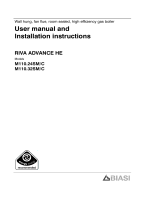
User manual and
Installation instructions
RIVA COMPACT
Models:
M90E.24S
M90E.28S
M90E.32S


Congratulations on your choice.
Your boiler is electronically controlled and has electr onic ignition.
The materials it is made of and the co ntrol systems it is equipped with give you safety, a high
level of comfort and energy savings to allow you to get the greatest benefit out of independent
heating.
Remember that...
n The manual must be read thoroughly, so
that you will be able to use the boiler in a safe
and sensible way;
must be carefully kept. It may be necessary
for reference in the future.
n First lighting up must be carried out by
competent and responsible engineer.
n The manufacturer disclaim all liability for
any translations of the present manual from
which incorrect interpretation may occur;
cannot be held r esponsible for non---observ-
ance of instructions cont ained in this manual
or for the consequences of any procedure
not specifically described.
Using the boiler...
n Before lighting the boiler,youaread-
vised to have a professionally qualified per-
son check that the installation of the gas
supply:
--- i s g a s --- t ig h t ;
---isofthecorrectgaugefortheflowtothe
boiler;
---is fitted with all the safety and control de-
vices required by the current Regulations;
Ensure that the installer has connected the
pressure relief valve outlet to a drain pipe.
The manufacturers are not responsible for
damage caused by opening of the pressure
relief valve and consequent escape of water,
if not connected correctly to the drain.
n On detecting the smell of gas
--- don’t operate any electrical switches, the
telephone or any device that may produce
sparks;
--- open the windows and doors at once to
create a draught of air which will purge the
area;
--- shut off the gas cocks;
--- get the assistance of a qualified person.
n Do not touch the appliance with parts of
thebodythatarewetordampand/orbare
feet.
n In case of structural wo rk or mainten-
ance near the exhaust duct and/or fume ex-
haust devices or their attachments, turn off
the appliance. On completion of the work,
have a professionally qualified person check
their efficiency.
n Repairs (under guarantee) must be car-
ried out only by an approved engineer, using
genuine spare parts. Thus do no more than
switching off the boiler yourself (see the in-
structions).
n Your boiler allows heating up of water to
a temperature less than boiling point;
--- must be connected to a central heating
system and/or a hot water supply system,
compatible with its performance and output;
--- can be used only for those purposes for
which it has been specially designed;
--- must not be touched by children or by
those unfamiliar with its operation;
--- must not be exposed to weather condi-
tions.

Safe handling of
substances
Biasi produ cts are manuf actured in accordance
with ISO 9000 and do not, and will not, contain any
hazardous materials or substances such as as-
bestos, mercury or C.F.C.’s.
The appliance packaging does not contain any
substances, which may be considered a hazard to
health.
Combustion chamber panels
Material: mineral fibers
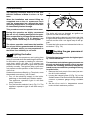
Known hazards --- Some people can suffer red-
dening and itching of the skin. Fibre entry into the
eye will cause foreign bod y irritation, which can
cause severe irritation to people wearing contact
lenses. Irritation to respiratory tract.
Precautions --- Dust goggles will protect eyes.
People with a history of skin complaints may be
particularly susceptible to irritation. High dust le-
vels are only likely to arise following harsh ab-
rasion. In general, normal handling and use will
not present high risk, follow good hygiene prac-
tices, wash hands before, touching eyes,consum-
ing food, drinking or using the toilet.
Firstaid --- Medicalattentionmustbesoughtfol-
lowing eye contact or prolonged reddening of the
skin.
Thermostat / Temperature gauge
Description --- Sealed phial and capillary contain-
ing liquid.
Known hazards --- irritating to skin, eyes and
throat. Vapour is h armful. Inflammable --- do not
extinguish with water.
Precautions --- Do not incinerate. Avoid contact
with broken/leaking phials. Do not purposely
puncture.
Firstaidmedicalattentionmustbesoughtfollow-
ing eyes/skin contact, wash with clean water.
Appliance category II
2H3+
Gas G20 20 mbar, G30 29 mbar, G31 37 mbar
Country of destination: United Kingdom (GB) Irealnd (IE)
This appliance conforms with the EEC directive 90/396 and, consequently, it has the right to make use
of the brand name
Moreover, the appliance conforms with the EEC directive 87/308 relative to the prevention and elimina-
tion of radio disturbances.
The appliance is b uilt to comply with the regulation now in force regarding gas appliance’s safety and
the European regulation now in force relative to safety of household and similar electrical appliances.
The manufacturer, in the continuous pocess to improve his products, reserves the right to modify the
data expressed in the present documentation at any time and without prior notice.
The present documentation is an informative support and it cannot be considered as a contract to-
wards third parties.

Boiler installation and commissioning tips
n The installation must be carried out by
a qualified person who will be responsible for
observing the current Regulations.
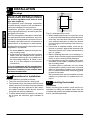
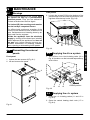
Installing the boiler...
n Donotforgettoremovethetransitcaps
and plugs from the boiler connections these
are fitted to every boiler.
n Keep the boiler clear of dust during in-
stallation and in particular do not allow any
dust or debris to enter the top of the boiler
where the flue connec tion is made. It is rec-
ommended that you put a dust sheet over the
top of the boiler until you are ready to make
the flue connection.
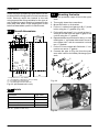
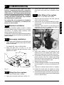
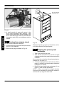
n Because every boiler is fired and tested
live at the factory, a small amount of water re-
mains within the boiler. It is possible for this
water to initially cause the pump to seize. It is
therefore recommended that the pump rotor
be manually turned to free its r o t atio n before
turning the boiler on.
n Remember to releas e the auto air purge
before filling the boiler. See the instructions to
identify the location of this device.
n Do not remove the cap of the pressure
test points of the air switch (top left side of the
boiler).
n You are strongly advised to flush out the
system both cold and hot in order to remove
system and installation debris.
n It is also sensible to initially fire and com-
mission the boiler before connecting any ex-
ternal controls such as a room thermostat. By
this method if you have a subsequent prob-
lem following the addition of an external con-
trol you can eliminate the boiler from your
fault analysis.
n Donotforgettorangeratetheboilerto
suit the system requirements. This pro-
cedure is covered in the commissioning sec-
tion of the installation manual.
n If the boiler is fitted with a digital pro-
grammer, when setting the times for auto-
matic operation, remember that for every
“ON” time there must be an “OFF” time to fol-
low and that on every occasion you enter a
time you must also indicate which days that
you want the boiler to follow the t i med set-
tings.
n Some products incorporate an anti cycl-
ing time delay. It is normal when first switch-
ing the boiler on for the boiler to operate on
heating for a few seconds then switch off.
After 3--- 4 minutes has elapsed the bo i ler will
then re ignite and operate perfectly normally.
The ignition delay cycle does not prevent
normal operation of the boiler to provide
d.h.w.
n If you are in any doubts as to the installa-
tion or operation of the boiler please read the
instruction manuals thoroughly and then if
necessar y contact Biasi UK for advice and
assistance.
Please remember that if you are in any doubt about the installation of this product you can contact our
Technical Helpli ne on tel. 0121 506 1350

TABLE OF CONTENTS
1 Appliance description 1..........
1.1 Overview 1......................
1.2 Control panel 1..................
1.3 Isolation valves 1.................
1.4 Technical data 1.................
2 Instructions for use 2............
2.1 Warnings 2......................
2.2 Refilling procedure 2..............
2.3 Ignition 3........................
2.4 C.h. circuit temperature 3..........
2.5 D.h.w. temperature 4..............
2.6 Extinguishing 4..................
2.7 Built in time switch A 5............
2.8 Built in time switch B 7............
3Usefuladvice 9.................
3.1 Central heating 9.................
3.2 F rost protection 9................
3.3 Periodic maintenance 9...........
3.4 External cleaning 9...............
3.5 Operational faults 9...............
4 Technical information 11..........
4.1 Overview 11......................
4.2 Main diagram 12..................
4.3 Hydraulic specifications 13.........
4.4 Expansion vessel 13...............
4.5 Technical data M90E.24S 14........
4.6 Technical data M90E.28S 16........
4.7 Technical data M90E.32S 18........
5 General requirements 20..........
5.1 Related documents 20.............
5.2 Location of appliance 20...........
5.3 Flue system 20....................
5.4 Gas supply 21....................
5.5 Air supply 21.....................
5.6 Ventilation 21.....................
5.7 Water circulation (c.h.) 21...........
5.8 Domestic water 22.................
5.9 Water treatment 22................
5.10 Electrical supply 22................
6 Installation 24....................
6.1 Warnings 24......................
6.2 Precautions for installation 24.......
6.3 Installing the bracket 24............
6.4 Overall dimensions 25.............
6.5 Joints 25.........................
6.6 Mounting the boiler 25.............
6.7 Fitting the flue system 26...........
6.8 Flue restrictors 26.................
6.9 Choice of flue 26..................
6.10 Electrical connections 28...........
6.11 External frost protection 30.........
7 Commissioning 31...............
7.1 Electrical installation 31............
7.2 Gas supply installation 31..........
7.3 Filling the d.h.w. system 31.........
7.4 Initial filling of the system 31........
7.5 Lighting the boiler 32..............
7.6 Checking the gas pressure
at the b urner 32...................
7.7 Adjusting the burner ignition 33.....
7.8 Adjustment of useful c.h. output 34..
7.9 Checking the ignition device 36.....
7.10 Checking the flue system 36........
7.11 Instructing the user 36.............
8 Gas conversion 37...............
8.1 Warnings 37......................
8.2 Procedures 37....................
9 Maintenance 39..................
9.1 Warnings 39......................
9.2 Dismantling the external panels 39...
9.3 Emptying the d.h.w. system 39......
9.4 Emptying the c.h. system 39........
9.5 Combustion analysis check 40......
9.6 Cleaning the primary
heat exchanger 40................
9.7 Checking the pressurisation
in the expansion vessel 41..........
9.8 Cleaning the burner 41.............
9.9 Checking the flue 41...............
9.10 Visual inspection of appliance 41....
9.11 Gas pressures and soundness 41...
Abbreviations used in the manual
C.h. = Central heating
D.h.w. = Domestic hot water
D .c.w. = Domestic col d water
USE
INSTALLATIONMAINTENANCE

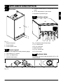
1 APPLIANCE DESCRIPTION
1
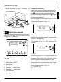
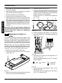
1.1 Overview
2
1
3
Fig. 1.1
1 Case front panel
2 Control panel
3 Control panel cover
1.2 Control panel
4 C.h. circuit temperature and pressure gauge
5 Time switch (c.h. control)
6 Lock --- out signal lamp
7 Lockout reset button
8 Function selector and c.h. temperature control
knob
9 D.h.w. temperature control knob
10 Appliance operation light
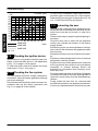
1.3 Isolation valves
13 1115 1214
Fig. 1.2 (bottom view of the boiler)
11 C .h. return valve
12 D.c.w. inlet valve
13 Gas inlet valve
14 D.h.w. outlet pipe
15 C.h. flow valve
1.4 Technical data
For detailed technical data see section 4.5 or 4.6
of this manual.
10 89 7 6 45
Fig. 1.3
USE

2 INSTRUCTIONS FOR USE
2
2.1 Warnings
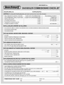
Biasi UK Ltd support the Benchmark initiat-
ive. The Benchmark Log Book is located a t
the back of this manual and should be com-
pleted by the Installing/Commisssioning
Engineer and ha nded over to the User for
future reference by other visiting En-
gineers. Also included is the Service Inter-
valRecordcardthatshouldbecompleted
by the Service Engineer following the a n-
nual service maintenance of the boiler and
system.
All CORGI Registered Installers carry a
CORGI ID card, and have a registration
number. Both should be recorded in your
Benchmark Log Book. You can check your
installer is registered by calling CORGI di-
rect on 01256 372300.
In order to guarantee safety and correct oper-
ation, it is essential that all the tests are carried
out by a competent and responsible service
engineer before lighting up the boiler.
The tests are described in the installation in-
structions in section 7 commissioning.
Ensure that the c.h. circuit is regularly filled
with water (even if the boiler is only used for
d.h.w. supply) checking that the pressure indi-
cated on the temperature and pressure gauge
4 is not lower than that shown in Fig. 2.2.
If the p ressure reading on the pressure gau ge
is below that shown in Fig. 2.2, then the system
will require topping up. A filling loop is normally
provided by the installer for this purpose.
If you are in any doubt regarding this pro-
cedure you are advised to contact your In-
staller or an Approved Engineer.
This appliance is provided with a built in anti---
freeze system that operates the boiler when
the temperature is below 4 ˚C
Therefore, when the boiler is not lit or used in
cold weather, with consequent risk of freezing
do not switch off the boiler at the fused spur
isolation switch or close the gas inlet cock.
When you do not expect to use the boiler for a
long period and the boiler is not to b e used for
frost protection then follow the instructions
giveninsection2.6onpage4.
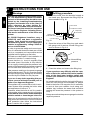
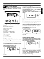
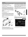
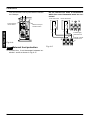
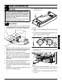
2.2 Refilling procedure
1 Isolate the boiler from the electrical supply at
the fused spur. Reconnect the filling loop as
demonstrated in Fig. 2.1.
Te mpo ra ry
connection
Control valve
Control valve
Double check valve
Supply pi pe
(cold water inlet)
C.h. return pipe
Fig. 2.1
2 Open the valves of the filling loop and watch
the gauge until it reaches normal filling pres-
sure as shown in Fig. 2.2.
4
Normal filling
pressure
Fig. 2.2
3 Close the valves and remove the filling loop.
If you experience any difficulty with the oper-
ation of the boiler, switch off the boiler immedi-
ately at the fused spur isolation switch and
contactyourInstalleroranapprovedService
Engineer
Air introduced into the boiler during this filling pro-
cess will vent through the automatic air purger
fitted to the boiler. You may also find it necessary
to vent air from your radiator circuit using your
radiator key, however be aware that excessive
venting will cause the pressure in the system to
drop.
Always ensure that the p ressure gauge is set at the
required pressure.
USE

Instructions for use
3
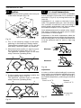
2.3 Ignition
1 Check that the valves located in the lower part
of the boiler are open (Fig. 2.3).
Open position
Fig. 2.3
2 Turn on the electricity supply to the boiler,
switching on the fused spur isolation switch.
The appliance operation light 10 (Fig. 2.4) will
flash every 4 seconds (stand--- by condition).
3 If the boileris to be used for c.h. and d.h.w p osi-
tion the function selector 8 as in Fig. 2.4.
The appliance operation light 10 will flash
every 2 seconds (operating boiler).
810
Fig. 2.4
4 If d.h.w. supply only is required, position the
function selector 8 as in Fig. 2.5.
The appliance operation light 10 will flash
every 2 seconds (operating boiler).
810
Fig. 2.5
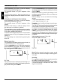
2.4 C.h. circuit temperature
The output temperature of c.h. water is adjustable
from a minimum of about 38°C to a maximum of
about 85°C (Fig. 2.6), by turning the function se-
lector (8).
Adjustment of c.h. output on the boiler is auto-
matic. The greatest output pre--- set in the factory
can, however, be reduced in level according to
actual system requirements; this does not affect
the maximum output in d.h.w. operation.
Such adju stments must be carried out by a quali-
fied person; therefore we advise you to contact
yourinstallerorServiceAgent.
Adjustment of the boiler temperature alters the
gas flow at the burner according to the thermal de-
mand in the system. So it is usual to see the burner
lit at the minimum level for more or less long
periods.
Minimum
Maximum
Fig. 2.6
Adjustment
In order to achieve optimal settings for economy
and comfort, we recommend adjusting the oper-
ating temperature of the c.h. water according to
the outside temperature, positioning the knob as
follows:
Lower than
--- 5 ˚C
From 5 to 15 ˚C
Between
--- 5 a n d + 5 ˚C
Fig. 2.7
USE

Instructions for use
4
Your qualified installer will be able to recommend
the most suitable adjustment for your system.
The temperature and pressure gauge (4, Fig. 1.3
on page 1) will allow you to check that the set tem-
perature is obtained.
2.5 D.h.w. temperature
The temperature of the d.h.w. leaving the boiler
can be varied from a minimum of about 35°Ctoa
maximum of about 55°C (Fig. 2.8), by turning the
temperature control knob 9.
Minimum
Maximum
9
Fig. 2.8
Adjustment of the d.h.w . temperature is complete-
ly separate from that of the c.h. circuit.
The adjustment system integrated within the
boiler automatically controls the flow of gas to the
burner in order to keep the temperature of d.h.w.
delivered constant, between the limits of maxi-
mum and minimum output.
Where the demand is at a low level or with the tem-
perature set to the minimum, it is normal to see a
cycle of lighting and extinguishing of the burner
when running.
Adjustment
It is advisable to adjust the d.h.w. temperature to
a level commensurate with the demand, minimis-
ing the need to mix with cold water. In this way, the
automatic control facilities will be fully exploited.
Moreover, where the amount of limescale p resent
in the water may be particularly great, not exceed-
ing the position in Fig. 2.9 of the d.h.w. tempera-
ture control knob 9 corresponding to about 50°C
(Fig. 2.9), minimises annoying incidences of scale
deposits and clogging.
9
Fig. 2.9
In these cases, however, it is advisable to install a
small water treatment device or softener. With
such a device you should avoid periodic descal-
ing.
Consequently, the d.h.w. heat exchanger will keep
its performance consistent for a longer period of
time with resulting gas savings.
If the demand for d.h.w. is so great as to prevent
reaching a high enough temperature, have the ap-
propriate output limiting valve installed by your in-
staller or an Authorised Service Engineer.
2.6 Extinguishing
To turn the boiler off set the function selector 8 to
the position shown in Fig. 2.10.
The appliance operation light 10 will flash every 4
seconds.
810
Fig. 2.10
When you do not expect to use the boiler for a long
period:
1 Switch off the electricity supply to the boiler, by
means of the fused spur isolation switch;
2 Shut off the gas supply cock 13 and the valves
for the water circuits fitted under the boiler
(Fig. 2.11).
USE

Instructions for use
5
3 Empty the water circuits, if necessary, as
shownintheinstallation instructions in the sec-
tion maintenance.
Closed position
13
Fig. 2.11
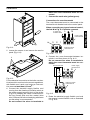
2.7 Built in time switch A
The combiboilers are equipped with a built in elec-
tronic time switch (5, Fig. 1.3 on page 1) which
controls the c.h. operation.
H
A
BCDEF
G
Fig. 2.12
Display and control panel
A Mode selector switch
B Reset button
C Enter button
D Increase “+” setting button
E Decrease “ --- ” setting button
F O n --- o f f b u t t o n
G Time display
H O N --- O F F d i s p l a y
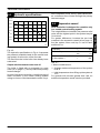
Setting the current time
Note: with a new unit or when the reset button B
has been pressed and the selector switch A is to
the
position, the time display G is flashing.
Set the mode selector switch A to the
position
and press the buttons D or E until the current time
appears in the display G.
The clock starts by moving the switch A to the
AUTO position.
Setting example shown in Fig. 2.13:
Current tim e 16.30.
A
Fig. 2.13
Setting the switching time
20 memory locations are available, corresponding
to 10 on--- off sequences.
Set the mode selector switch A to the C1 position.
The symbols shown in Fig. 2.14 appears in the
display.
A
Fig. 2.14
Press the buttons D or E to set the desired ON
time.
Press the “enter” button C to confirm the setting
and to continue programming the OFF time.
SettheOFFtimeasexplainedabovefortheON
setting and confirm by pressing the “enter” button
C. Proceed in the same way for other settings.
Setting example shown in Fig. 2.15:
A --- ON time 7.45.
B --- OFF time 10.30.
USE

Instructions for use
6
AB
Fig. 2.15
Activating the timed settings
Set the mode selector switch A to the AUTO posi-
tion shown in Fig. 2.16.
The current time appears in the display. The ON---
OFF display H indicates the current state of oper-
ation (according to the settings).
A
Fig. 2.16
Note: when the mode selector switch A is in the
AUTO position and the boiler is switched off at the
fused spur isolation switch, the display H indicates
only the OFF state. The other indications are
blanked.
Reading the timed settings
Set the mode selector switch A to the C1 position.
The symbols shown in Fig. 2.14 appears in the
display.
Press the “enter” button C. Each time the button
is pressed the display shows the details of the next
setting.
Changing or deleting the timed settings
Set the mode selector switch A to the C1 position.
The symbols shown in Fig. 2.14 appears in the
display.
Press the “enter” button C until the display shows
the setting to be modified or deleted.
Thetimesettingcanbemodifiednowbypressing
button D or E and the operation can be switched
on or off by pressing the button F.
To delete a time set press the button D or E until the
symbols shown in Fig. 2.14 appears in the time
display G.
The new settigs are memorized by moving the
switch A to a different position.
Manual operation
The operation of the time switch can be forced on
or off constantly or for a timed period.
To fo r c e constantly on or off the timer operation
set the mode selector switch A to the TIMER posi-
tion. The symbols shown in Fig. 2.17 appears on
the display.
Fig. 2.17
The operation can be switched permanently on or
off by pressing the button F and leaving the switch
AintheTIMER position.
To f o rce atimeddelayon or off operation, set the
mode selector switch A in the TIMER position.
Set the time delay by pressing the button D or E
and t he operation can be forced on or off by pres-
sing the button F.
Thetimedelaycanbesetwithinthefollowing
ranges:
1to23hourswithstepsof1hour
1to27dayswithstepsof1day
The time delay setting is activated by moving the
switch A to the AUTO position.
The ON--- OFF display H flashes indicating that the
current state of operation has been forced.
To delete the timed delay setting, set the mode se-
lector switch A in the TIMER position, press the
button D or E until the symbols shown in Fig. 2.17
appears in the display and then set the mode se-
lector switch A to the AUTO position
Setting example shown in Fig. 2.18:
forced ON state for 4 hours.
Fig. 2.18
Resetting
To completely reset the timer, press the reset but-
ton with a pointed object (pencil).
CAUTION: pushing the reset button will complete-
ly erase the settings as well as all the data, includ-
ing the current time.
USE

Instructions for use
7
2.8 Built in time switch B
The combiboilers are equipped with a built in elec-
tronic time switch which controls the c.h. oper-
ation.
H
A
BCD EF
G
Fig. 2.19
Display and control panel
A Mode selector switch
B Reset button
C OK button
D Increase “+” setting button
E Decrease “ --- ” setting button
F O n --- o f f b u t t o n
G Time display
H O N --- O F F d i s p l a y
Setting the current time
Press repeatedly the button A until the display
shows the symbol
Press the buttons D or E until the current time ap-
pears in the display G.
The clock starts by pressing the button A to show
the symbol AUTO.
Setting example shown in Fig. 2.20:
Current tim e 16.30, day Thursday.
A
Fig. 2.20
Setting the switching time
28 memory locations are available, corresponding
to 14 on--- off sequences.
Press repeatedly the button A until the display
shows the symbol C1 (Fig. 2.21)
The symbols shown in Fig. 2.21 appears in the
display.
A
Fig. 2.21
Press the buttons D or E to set the desired ON
time.
Press the “OK” button C to confirm the setting and
to continue programming the OFF time.
SettheOFFtimeasexplainedabovefortheON
setting and confirm by pressing the “enter” button
C. Proceed in the same way for other settings.
Setting example shown in Fig. 2.22:
A --- ON time 7.45.
B --- OFF time 10.30.
AB
Fig. 2.22
Activating the timed settings
The current time appears in the display. The ON---
OFF display H indicates the current state of oper-
ation (according to the settings).
A
Fig. 2.23
Note: when the display shows the symbol AUTO
and the boiler is switched off at the fused spur
isolation switch, the display H indicates only the
OFF state. The other indications are blanked.
Reading the timed settings
USE

Instructions for use
8
Press repeatedly the button A until the display
shows the symbol C1 (Fig. 2.21)
The symbols shown in Fig. 2.21 appears in the
display.
Press the “OK” button C. Each time the button is
pressed the display shows the details of the next
setting.
Changing or deleting the timed settings
Press repeatedly the button A until the display
shows the symbol C1 (Fig. 2.21)
The symbols shown in Fig. 2.21 appears in the
display.
Press the “OK” button C until the display shows
the setting to be modified or deleted.
Thetimesettingcanbemodifiednowbypressing
button D or E and the operation can be switched
on or off by pressing the button F.
To delete a time set press the button D or E until the
symbols shown in Fig. 2.21 appears in the time
display G.
The new settings are memorised by pressing the
button A.
Manual operation
The operation of the time switch can be forced on
or off constantly or for a timed period.
To fo r c e constantly on or off the timer operation
press repeatedly the button A until the display
shows the symbol TIMER. The symbols shown in
Fig. 2.24 appears on the display.
A
Fig. 2.24
The operation can be switched permanently on or
off by pressing the button F and leaving the dis-
play shows the symbol TIMER.
To f or c e atimeddelayon or off operation, press
repeatedly the button A until the display shows the
symbol TIMER.
Set the time delay by pressing the button D or E
and t he operation can be forced on or off by pres-
sing the button F.
Thetimedelaycanbesetwithinthefollowing
ranges:
1to23hourswithstepsof1hour
1to27dayswithstepsof1day
Press the button A untilthe display shows the sym-
bol AUTO.
The ON--- OFF display H flashes indicating that the
current state of operation has been forced.
To delete the timed delay setting, press repeatedly
the button A until the display shows the symbol
TIMER, press the button D or E until the symbols
showninFig.2.25appearsinthedisplayandthen
press the button A untilthe display shows the sym-
bol AUTO.
Setting example shown in Fig. 2.25:
forced ON state for 4 hours.
A
Fig. 2.25
Note:If during manual operation, power supply
turns off, timer must be set again following previ-
ous steps
Resetting
To completely reset the timer, press the reset but-
ton with a pointed object (pencil).
CAUTION: pushing the reset button will complete-
ly erase the settings as well as all the data, includ-
ing the current time.
USE

3 USEFUL ADVICE
9
3.1 Central heating
For reasonably economical service install a room
thermostat.
Never shut off the radiator in the area where the
room thermostat is installed.
If a radiator (or a convector) does not heat up,
check that no air is present in it and that its valve
is open.
If the ambient temperature is too high, do n ot alter
the radiator valves. Reduce the central heating
temperature instead by means of the room ther-
mostat and the function selector (8 in Fig. 3.1).
8
Fig. 3.1
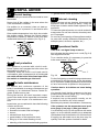
3.2 Frost protection
This appliance is provided with a built in anti---
freeze system that operates the boiler when the
temperature is below 4 ˚C
Therefore, when the boiler is not lit and used in
cold weather, with consequent risk of freezing do
not switch off the boiler at the fused spur isola-
tion switch or close the gas inlet cock.
3.3 Periodic maintenance
For efficient and continuous operation of the
boiler, it is advisable to arrange maintenance and
cleaning by an Authorised Service Centre En-
gineer, at least once a year.
During the service, the most important compo-
nents of the boiler will be inspected and cleaned.
This service can be p art of a maintenance con-
tract.
In particular, you are advised to have the following
checks carried out:
--- primary heat exchanger;
--- domestic hot water heat exchanger;
--- burner;
--- exhaust fume duct and flue;
--- pressurisation of the expansion tank;
--- filling up of the central heating circuit;
--- bleeding of air from the central heating system;
--- general check of the appliance’s operation.
3.4 External cleaning
Before carrying out any cleaning, disconnect the
appliance from the electrical mains, using the
fused spur isolation switch fitted adjacent to the
appliance.
To clean the external panels, use a cloth soaked in
soapy water. Do not use solvents, abrasive p owd-
ers or sponges.
Do not carry out cleaning of the appliance and/or
its parts with readily flammable substances (for
example petrol, alcohols, naphtha, etc.).
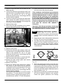
3.5 Operational faults
If the lock--- out signal lamp comes on
this indicates that the safety lock--- out 6 (Fig. 3.2)
has stopped the boiler
To re--- start the boiler, it is necessary to pr ess the
boiler reset button 7 (Fig. 3.2).
7
6
Fig. 3.2
For the first lighting up and following maintenance
procedures for the gas supply, it may be necess-
ary to repeat the resetting operation several times
so as to remove the air present in the pipework.
If noises due to a ir bubbles ar e heard during
operation...
you should check that the pressure on the tem-
perature and pressure gauge (Fig. 2.2 on page 2)
is not below the correct setting.
If required, top up the system correctly, as de-
scribed in the section 2.2 of this manual.
Bleed any air pr esent in the radiators, if necessary.
If the pressure on the temperature and pres-
suregauge(4onpage1)hasgonedown...
it is necessary to top up the appliance with water
again, so as to raise the pressure to an ad equate
level as described in the section 2.2 of this manual.
If topping up with water has to be done very fre-
quently, have the system checked for leaks.
USE

Useful advice
10
If water comes out of the pressure relief valve
Check on the temperature and pressure gauge (4
on page 1) that the pressure in the central heating
circuit is not close to 3 bars. I n this case, tempera-
ture rise in the circuit can cause the pressure relief
valve to open.
So that this does not happen and to decrease the
pressure to a normal value, it is advisable to vent
some of the water in the appliance through the
bleed valves present in the radiators.
If in time, a reduction in domestic hot water
supply is observed...
The likely causes may be impurities caught in the
domestic hot water flow switch filter or limescale
deposited in the domestic hot water heat ex-
changer. It is advisable to have the ap p liance
cleaned out by an Authorised Service Centre En -
gineer.
If water should occasionally leak from the
boiler...
shut off the valves positioned under the boiler
(Fig. 2.11 on page 5) and call an Authorised Ser-
vice Centre Engineer.
If the appliance operation light 10 (Fig. 3.3)
flashes very quickly the boiler is faulty.
10
Fig. 3.3
In this case or in case of problems other than
those mentioned here, switch off the boiler, as
describedinsection2.6onpage4andcalla
competent a nd responsible service engineer.
USE

4 TECHNICAL INFORMATION
11
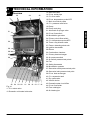
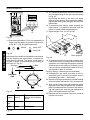
4.1 Overview
17
31
30
28
29
24
27
21
35
26
25 1822
34
19 16
32
33
2023
Fig. 4.1
11 C .h. return valve
12 Domestic cold water inlet valve
13 Gas inlet valve
14 D.h.w. outlet pipe
15 C.h. flow valve
16 D.h.w. temperature p robe NTC
17 Main circuit drain valve
18 C.h. pressure relief valve
19 Pump
20 Pump vent plug
21 Automatic air purger valve
22 D.h.w. flow switch
23 Modulation gas valve
24 Primary circuit flow switch
25 C.h. temperature probe NTC
2 6 T h r e e --- w a y d i v e r t e r v a l v e
27 Flame---detecting electrode
28 Ignition electrodes
29 Burner
30 Combustion chamber
31 Primary heat exchanger
32 Air pressure switch
33 Air switch pressure test points
34 Fan
35 Safety thermostat
36 Modulation operator
37 Gas valve outlet pressure test point
38 Gas valve inlet pressure test point
39 D.h.w. heat exchanger
40 C.h. expansion tank
4 1 B y --- p a s s v a l v e
42 Venturi device
43 Domestic water circuit filter
44 D.h.w. flow limiter
45 Flue outlet pipe
46 Air intake pipe
INSTALLATION

Technical information
12
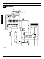
4.2 Main diagram
42
32
46
45
24
31
28
37
19
18
22
23
38
21
26
39
41
43
11
12
15
13
40
34
27
25
16
14
36
35
29
17
44
Fig. 4.2
INSTALLATION

Technical information
13
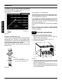
4.3 Hydraulic specifications
0.0
0.1
0.2
0.3
0.4
0.5
0.6
0 200 400 600 800 1000 1200 1400
0
10
20
30
40
kPa bar
l/h
60
50
Fig. 4.3
The hydraulic specifications in Fig. 4.3 represent
the pressure (available head for the central heat-
ing system) as a function of the flow rate.
The load loss due to the boiler has already been
subtracted.
Output with thermostat cocks shut off
The boiler is fitted with an automatic by--- pass
valve (41 on page 11), which protects the primary
heat exchanger.
In case of excessive reduction or total blockage of
water circulation in the central heating system
owing t o closure of the thermostatic valves or sys-
tem component cocks, the by---pass valve ensur-
es a minimum flow of water through the primary
heat exchanger.
4.4 Expansion vessel
Note:thisboilerisdesignedforoperationonly
in a sealed central heating system
The height difference between the pressure relief
valve and the highest point in the system may be
7m at most.
For greater differences, increase the pre--- load
pressure in the expansion vessel (40 on page 11)
and the system, when cold, by 0.1 bar for each
additional 1m.
Capacity
l 6,0
P r e --- l o a d p r e s s u r e kPa
bar
100
1,0
Maximum volume of water
in the system *
l 104
Tab . 4 . 1
* Where conditions are:
--- Average maximum temperature of the system
is 80°C
--- Initial temperature when filling up the system is
10°C
F o r systems with volumes greater than 104l, an
additional expansion vessel must be provided.
INSTALLATION

Technical information
14
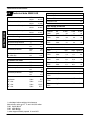
4.5 Technical data M90E.24S
Nominal heat input kW
BTU/h
26,6
90 754
Minimum heat input kW
BTU/h
11,0
37 530
Maximum useful output kW
BTU/h
24,3
82 906
Minimum useful output kW
BTU/h
9,1
31 047
Central heating
Maximum temperature ˚C 85
Minimum temperature ˚C 38
Maximum pressure kPa
bar
250
2,5
Minimum pressure kPa
bar
30
0,3
Available h ead
(in 1000 l/h)
kPa
bar
27
0,27
Domestic hot wa ter
Maximum temperature ˚C 55
Minimum temperature ˚C 35
Maximum pressure kPa
bar
1 000
10
Minimum pressure kPa
bar
30
0,3
Flow rate
minimum l/min 2,5
30˚ rise l/min 11,6*
35˚ rise l/min 10,0*
40˚ rise l/min 8,7*
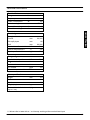
Injectors
Natural G20 130
Butane G30 77
Propane G31 77
Gas supply pressures
Gas norm. min max
Natural
G20
Pa
mbar
2 000
20
1 700
17
2 500
25
Butane
G30
Pa
mbar
2 900
29
2 000
20
3 500
35
Propane
G31
Pa
mbar
3 700
37
2 500
25
4 500
45
Gaspressuresattheburner
Gas min max Ignition
Natural
G20
Pa
mbar
180
1,8
1 170
11,7
600
6,0
Butane
G30
Pa
mbar
500
5,0
2 760
27,6
1 200
12
Propane
G31
Pa
mbar
610
6,1
3 570
35,7
1 300
13
Gas rate
Gas min max
Natural
G20
m
3
/h 1,16 2,82
Butane
G30
kg/h 0,87 2,09
Propane
G31
kg/h 0,85 2,06
* calculated values subject to tolerance
Net calorific value at 15 ˚C and 1013,25 mbar
G 20 34,02 MJ/m
3
G 30 45,6 MJ/kg
G 31 46,4 MJ/kg
1 mbar approximately equals 10 mm H
2
O
INSTALLATION
Page is loading ...
Page is loading ...
Page is loading ...
Page is loading ...
Page is loading ...
Page is loading ...
Page is loading ...
Page is loading ...
Page is loading ...
Page is loading ...
Page is loading ...
Page is loading ...
Page is loading ...
Page is loading ...
Page is loading ...
Page is loading ...
Page is loading ...
Page is loading ...
Page is loading ...
Page is loading ...
Page is loading ...
Page is loading ...
Page is loading ...
Page is loading ...
Page is loading ...
Page is loading ...
Page is loading ...
Page is loading ...
Page is loading ...
Page is loading ...
Page is loading ...
Page is loading ...
-
 1
1
-
 2
2
-
 3
3
-
 4
4
-
 5
5
-
 6
6
-
 7
7
-
 8
8
-
 9
9
-
 10
10
-
 11
11
-
 12
12
-
 13
13
-
 14
14
-
 15
15
-
 16
16
-
 17
17
-
 18
18
-
 19
19
-
 20
20
-
 21
21
-
 22
22
-
 23
23
-
 24
24
-
 25
25
-
 26
26
-
 27
27
-
 28
28
-
 29
29
-
 30
30
-
 31
31
-
 32
32
-
 33
33
-
 34
34
-
 35
35
-
 36
36
-
 37
37
-
 38
38
-
 39
39
-
 40
40
-
 41
41
-
 42
42
-
 43
43
-
 44
44
-
 45
45
-
 46
46
-
 47
47
-
 48
48
-
 49
49
-
 50
50
-
 51
51
-
 52
52


Biasi Riva Compact M90E.24S, M90E.28S, M90E.32S User manual
- Category
- Water heaters & boilers
- Type
- User manual
Ask a question and I''ll find the answer in the document
Finding information in a document is now easier with AI
Related papers
-
 Biasi Riva Advance M110.24SM/C, M110.32SM/C User manual
-
 Biasi Riva Plus HE M296.24SM/C, M296.28SM/C User manual
-
 Biasi Garda Plus M110.24SM/E, M110.32SM/E User manual
-
Biasi Activ A 30C User manual
-
Biasi Advance Plus 25S, 30S User manual
-
 Biasi Parva HE M96.28SR/P, M96.32SR/P User manual
-
 Biasi Advance System User manual
-
 Biasi ActivA 18S, 25S, 30S User manual
-
 Biasi Advance 25C User manual
-
 Biasi Advance Combi User manual


Other documents
-
 Protherm 23 BTVE User, Installation And Servicing Instructions
-
Sime SUPER 80 Installation guide
-
-
-
-
-
-
Optima Company Optima 1001 User manual
-
 Unical FOKOLUS Installation guide
-
Ariston Benchmark System A 30 RFF User manual

