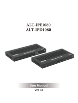
Wyrestorm NHD-200-TX User manual

Category
Networking
Type
User manual

This manual is also suitable for

WyreStorm HD over IP Solutions
Part Number NHD-000-CTL
NHD-200-TX
NHD-200-RX
NHD-210-RX
HD over IP AV distribution solution
utilising H.264 compression for
AV switching and video wall
functionality over a LAN
Instruction Manual
Thank you for choosing this WyreStorm product.
Please read these instructions carefully before installing to avoid complications later.
2
Technical Support: support@wyrestorm.com US: +1 866 677 0053 EU: +44 (0) 1793 230 343
CONTENTS
Contents
1
Introduction
2
Features
3
Safety Precautions
4
In the Box
5
Before Installation
6
Specications
7
Panel Description
8
Connection
9
Typical Application
i. One Encoder to One Decoder
ii. One Encoder to Multiple Decoders
iii. Multiple Encoders to Multiple Decoders
iv. Video Wall
10
Switch Settings and Requirements
11
NHD-000-CTL Browser Conguration & Control
i. Matrix Switching Commands
ii. TX/RX Settings
iii. CTL Settings
12
NetworkHD™ Console Conguration
i. NetworkHD™ Console Software Installation
ii. Searching Devices
iii. Setting Device Parameters
iv. Device Settings
v. Creating Scenes
vi. Sample Video Wall Set Up
vii. Video Wall Conguration
viii. Video Wall Properties
ix. Conguration File Management
x. Serial Control
xi. CEC Control
xii. Viewing the Encoders Preview Stream
xiii. Log
13
Additional Information
14
NetworkHD™ Protocol
15
Troubleshooting
16
FAQ
17
Maintenance
18
Provided Service
19
Mail In Service
20
Warranty
21
Warranty Limits and Exclusions
22
Disclaimer
23
Installation Reference Logs
3
Technical Support: support@wyrestorm.com US: +1 866 677 0053 EU: +44 (0) 1793 230 343
INTRODUCTION AND FEATURES
1. Introduction
WyreStorm
®
NetworkHD™ 200 is our agship H.264 HD over IP distribution platform. With its simple system conguration
and powerful video wall functionality it is the best all round solution for commercial AV installs. Enabling the distribution of
multiple video formats over a dedicated IP network switch for commercial AV applications.
NetworkHD™ 200 series facilitates the transmission of an HDMI, DVI, Component & VGA signals (including Full HD 1080p video with
2.1 audio) to any number of HDMI displays over standard Ethernet (Cat5e/6) infrastructure. The NHD-200-RX enables the display of a
single image on a display whilst the NHD-210-RX decoder adds video wall playback to the system.
The modular system architecture of NetworkHD™ 200 removes the limitations of a traditional xed platform I/O matrix system without
compromising quality or reliability, whilst oering signicant cost savings when designing large scale installations. Adding encoders and
decoders as required enables the system to grow with the needs of the application.
NetworkHD™ 200 uses multiple technologies to automatically congure and discover system components, making setup a breeze.
Functioning on 10/100 or Gigabit Layer2 SMART switches, NetworkHD™ 200 does not require advanced integrator network
experience to install, nor does it require complicated VLAN congurations or PC software, making it one of the simplest HD over IP
systems available. Conguring network switches takes minutes through your browser and even the largest distributions can be quickly
and easily congured and expanded.
The NHD-000-CTL controller creates a simple, single interface to congure, manage and control the entire NetworkHD™ 200 system,
whilst also capable of fully integrating with leading control brands including WyreStorm Enado
TM
for the highest quality total HD
distribution and control solution over a network.
For further information on this product and other WyreStorm ranges, visit our website or download our latest product guide at
wyrestorm.com
2. Features
Highly scalable, visually lossless HD over IP solution using the most ecient compression technology to allow for
very large commercial AV deployments
Powerful video wall functionality (NHD-210-RX only) up to 4 x 4 displays.
Multi-format DVI-I input selectable to HDMI, DVI, Component, VGA & Composite input
Plug and Play setup with automatic networking conguration and auto discovery of components
Quick Sync
TM
technology for virtually instantaneous, seamless switching
CEC One-Touch Play & Standby or RS-232 control of connected displays
Supports video previewing on a PC or third party device. NetworkHD™ 200 outputs simultaneous IP streams. One
full resolution for the NHD-200-RX. The other small one supports resolutions of 352 x 288 @ 5Hz to easily preview
a video from the encoder on a PC or Mac
Use with the new NHD-000-CTL controller for simple conguration and control via the LAN, as well as for allowing
control from third party control system such as AMX, Crestron, Control4, RTI & WyreStorm
TM
Enado.
Supports PoE to enable remote powering from POE network switches, eliminating the need for a nearby power
outlet
Full PC control suite available free of charge at wyrestorm.com
Supports HDCP
Audio Breakout on both Encoder & Decoder
Congurable encoding bit rate up to 40 Mbps
4
Technical Support: support@wyrestorm.com US: +1 866 677 0053 EU: +44 (0) 1793 230 343
SAFETY PRECAUTIONS AND IN THE BOX
3. Safety Precautions
WARNING
To reduce the risk of re, electric shock
or product damage:
4
Technical Support: [email protected] US: +866 677 0053 EU: +44 (0) 1793 230 343
FEATURES AND SAFETY PRECAUTIONS
MX0404-QI
Quick and easy installation – set up in seconds straight out of
the box.
Simplied ports - Input: HDMI – Output: integrated RJ45
connectors for a single Cat5e/6/7 UTP cable to each display
point for ease of installation.
Conforms to IEEE-568B standards
Each HDMI port also supports DVI signals.
Each Output port can be fed to multiple displays (cascaded).
Enables up to 4 HDMI video/audio devices to be independently
switched through up to 4 HDMI displays or projectors for
uncompressed digital distribution.
Each output able to show any connected source simultaneously
regardless of whether the input carries HDCP encryption.
Rened for Custom Install and Home Theatre Installations.
Reads and copies EDID from connected devices with additional
EDID configuration through customisable DIP switch settings if
necessary.
2k resolution supported.
Fully 3D compatible – Frame sequential 3D (Blu-ray) and
interlaced stereoscopic 3D (satellite broadcasts etc.)
Supports all high denition resolutions up to and including
1080p and standard video formats.
RS232 port.
Choose from 6 switching modes – infrared remote control, front
panel buttons, local IR, IR call-back, LAN and RS232.
Simple switching remote control included, which can also be
learned into a universal remote handset to allow the control of
multiple devices from one handset.
Fully compatible for integration with market leading control systems.
4 x IR 3.5mm mini-jack ports for each output to link IR from
control system to control display
Additional infrared extension port for longer IR connections
HDMI v.1.3
Supports 24Bit Colour depth
Signalling rate of 6.75 Gbps
Pack comes complete with 1 x 4x4 Matrix with 19” rack
brackets, 4 x 40m IR receivers with mounting brackets, IR
receivers, emitters and a Matrix remote control handset.
Additional features included on the RX-1UTP-IR-40
Transmits one-way signal together with the HDMI signal over a
single Cat5e/6/7 cable.
Receivers capable of 1080p transmissions up to 40m (131ft)
under ideal conditions*
For even greater control and ne tuning, each receiver features
a fully adjustable EQ distance range for optimising the
transmission signal.
2. Features
3. Safety Precautions
1. Do not expose this apparatus to rain, moisture, sprays,
drips or splashes and ensure that no objects containing
liquids are placed on the apparatus, including cups,
glasses and vases.
2. Do not place this unit in a confined space such as
enclosed shelving, cabinets or bookshelves. Ensure the
unit is adequately ventilated.
3. To prevent the risk of electric shock or fire hazard due to
overheating, do not cover the unit or obstruct ventilation
openings with material, newspaper, cardboard or
anything that may restrict airflow into the unit.
4. Do not install near external heat sources such as
radiators, heat registers, boilers or any device that
produces heat such as amplifiers or computers and do
not place near sources of naked flame.
5. Unplug apparatus from power supply during lightening
storms or when unused for long periods of time.
6. Protect the power cable from being walked on, pinched
or restricted in any way, especially at plug connections.
7. Only use attachments/accessories specified by the
manufacturer.
8. Units contain non-servicable parts - Refer all servicing to
qualified service personnel.
WARNING
To reduce the risk of fire, electric shock
or product damage:
Protection against ESD (electrostatic discharge) included within
the unit to further stabilise transmission.
LED indications for clear power and video signal selection.
5v mains supply included but receivers may be powered through the
USB port of the display using Wyrestorm USB to 5v power adaptor)
Fully cascadable to further lengthen transmission.
*NOTE: ideal conditions denote cable run is within
specified distance range of product, no electrical
interference, the use of straight cable runs with no bends
or kinks and no patch panels or wall outlets used. Please
be advised that the presence of any of these factors in
your installation may compromise bandwidth and signal
strength. For longer transmission distances, RS232 control
and Ethernet pass-through, please see our full HDBaseT
or HDBT Lite range of matrices, transmitters, receivers and
extender sets.
USB to 5V Cable
Part Number
CAB-USB-5V
1. Ventilation is crucial to consistent operation of this product. Units should be mounted with at least (2.5cm) 1 inch clearance of
vents. WyreStorm highly recommends the use of the NHD-000-RACK for absolute correct mounting best practice.
2. Do not expose this apparatus to rain, moisture, sprays, drips or splashes and ensure that no objects containing liquids are placed
on the apparatus, including cups, glasses and vases.
3. Do not place this unit in a conned space such as enclosed shelving, cabinets or bookshelves. Ensure the unit is adequately
ventilated.
4. To prevent the risk of electric shock or re hazard due to overheating, do not cover the unit or obstruct ventilation openings with
material, newspaper, cardboard or anything that may restrict airow into the unit.
5. Do not install near external heat sources such as radiators, heat registers, boilers or any device that produces heat such as
ampliers or computers and do not place near sources of naked ame.
6. Unplug apparatus from power supply during lightening storms or when unused for long periods of time.
7. Protect the power cable from being walked on, pinched or restricted in any way, especially at plug connections.
8. Only use attachments/accessories specied by the manufacturer.
9. Units contain non-servicable parts - Refer all servicing to qualied service personnel
4. In the Box
NHD-200-TX
1 x NHD-200-TX Main Unit
1 x Power Adapter (12V 1A DC)
3 x Detachable International Plugs
1 x HDMI to DVI Converter
1 x VGA to DVI Converter
1 x Component to DVI Converter
2 x Phoenix Connector (Male, 3.5 mm, 3 pin)
2 x Mounting Ears
NHD-200-RX
1 x NHD-200-RX Main Unit
1 x Power Adapter (12V 1A DC)
3 x Detachable International Plug s
3 x Phoenix Connector (Male, 3.5 mm, 3 pin)
2 x Mounting Ears
NHD-210-RX
1 x NHD-210-RX Main Unit
1 x Power Adapter (12V 1A DC)
3 x Detachable International Plug s
3 x Phoenix Connector (Male, 3.5 mm, 3 pin)
2 x Mounting Ears
NHD-000-CTL
1 x NHD-000-CTL Main Unit
1 x Power Adapter (12V 1A DC)
3 x Detachable International Plug s
1 x Phoenix Connector (Male, 3.5 mm, 4 pin)
2 x Mounting Ears
5
Technical Support: support@wyrestorm.com US: +1 866 677 0053 EU: +44 (0) 1793 230 343
BEFORE INSTALLATION
5. Before Installation
Introduction
This guide is intended for installation project managers to ensure you are aware of WyreStorm’s installation best practice guidelines that
we know will improve the installation experience. These issues have been gathered from thousands of installation reports, support calls
and our own personal experiences to prevent issues that cost hours in troubleshooting and protracted site visits to x.
Preparation
Build and test the rack and all hardware components o site. Doing so will nd any issues before moving to the hectic and time
sensitive environment of the install itself. Knowing that a unit was working properly before makes it far easier to pinpoint the cause of
the problem saving time and money.
Network Equipment & Switches
NetworkHD™ can be operated with recommended Layer 2 Gigabit Smart Switches provided the overall switching capacity or
backplane capacity of the switch meets the requirements of the number of encoders/decoders you have on your network.
WyreStorm NetworkHD is built to run over a standard network infrastructure, however the quality of this infrastructure is critical. We
have tested many brands of switches all of which perform well in small system congurations of around 10 Encoders and Decoders.
However, for larger installations, WyreStorm highly recommends using CISCO SG500 or CATALYST series switches.
NetworkHD requires a Layer 2 managed switch with support for Multicast & IGMP snooping enabled. Do not connect any encoders to
the switch until this has been congured. For recommended switches and PDF conguration guides please see the ‘downloads’ section
of any NetworkHD device at wyrestorm.com.
It is not necessary to change the IP addresses of the TX and RX units – AutoIP is used to congure correct IP addresses. DHCP or
Static IP addresses are not recommended unless absolutely required. Failure to note or errors in the IP settings of a unit may result in a
complicated reset procedure.
Most NetworkHD installations use POE (Power Over Ethernet) to power the RX & TX units. NetworkHD 100 & 200 components are
Class 0 rated POE devices meaning that they can require up to 15.4W of power each, however their real power draw is between 5-7W.
In order to calculate the number of devices that can be used on a switch please divide the total POE power capability of the switch
by 15.4 and round down. For Example the CISCO SG300-52P with a POE power output of 375W: 375 / 15.4 = 24.35. Therefore 24
devices can be powered by this switch.
In order to have all ports powered by POE on a switch an MP series should be used in this example an SG300-52MP which provides
740W. 740 / 15.4 = 48. Therefore 48 devices can be powered by this switch.
Each NHD-100-TX encoder will produce up to 50Mb/s of data > therefore 10 x encoders will require 10 x 50Mb/s = 0.5 Gbps.
!
If you are unsure about the network requirements for your NetworkHD™ system please contact WyreStorm or your
local WyreStorm distribution partner for support. WyreStorm are not liable if network bandwidth is to blame for poor
performance from the NetworkHD™ system.
NetworkHD™ does not require multiple VLANs to be configured. Third-party controllers communicate directly with the NHD-000-CTL
rather than the Ethernet switch.
Visit wyrestorm.com for guides on detailed switch configuration and recommended switch suggestions for different sized
NetworkHD™ systems.
Power
Your installation is nothing without power. Use a UPS (Uninterruptible Power Supply) to ensure a clean, consistent power supply to all
components in the rack. Be sure to calculate your total load and run time requirements ahead and leave enough room in the rack.
Heat
High temperatures are the biggest killer of electronic products. Just a 3° Celsius rise in external temperature can equate to a 15° degree
rise in internal temperature and trigger thermal runaway. Ensure proper rack design and passive or active cooling strategies are used to
properly move heat away from the components in the rack. Poor installation of cables looks messy and creates hotspots that prevent
heat moving away from components – avoid this at all costs.
6
Technical Support: support@wyrestorm.com US: +1 866 677 0053 EU: +44 (0) 1793 230 343
BEFORE INSTALLATION
The NHD-IP-RACK & NHD-000-RACK have been designed for optimal mounting of the NetworkHD Encoders in the rack and should
always be used. Encoders and decoders should never be laid at or stacked on top of each other. At least 1.5 inches of clearance
should be left by the vents to ensure adequate airow through the units.
Software
Where possible WyreStorm ship all components with the most up to date rmware and software, however before starting any
installation please check the downloads section of the products on WyreStorm.com to ensure there are no updates to your system
components. Please also try to use the latest rmware on all related hardware – particularly switches and TVs. Please check with the
relevant manufacturer for upgrade instructions.
Redundancy
With all the planning in the world, even the most experienced installers make mistakes and accidents will always happen. For this
reason, it is best practice to always run two cables to each Decoder location. This may increase the cost of cabling but is nothing
compared to replacing a single or even multiple defective cables that have been sealed into the wall.
Although WyreStorm are incredibly proud of the reliability and robustness of our products from time to time units can fail. Therefore,
mission critical products such as the CTL and Decoders in hard or impossible to access locations should be installed with spare,
redundant units that can be swapped to if required.
Mounting/Installation
All WyreStorm products should be mounted so that the logo and text printed on the unit is correctly aligned. This will allow for the
optimal airow through the product. As already stated the vents should not be obstructed with adequate clearance. Units should be
secured using suitable xings such as those supplied in the box.
Source & Display settings
WyreStorm NetworkHD components use the highest quality encoders available to provide visually lossless compression over a large
number of displays. However, the compression can only be as good as the source content that is put in. NetworkHD 100/200 series
use H.264 compression that is not compatible with interlaced sources. Please ensure that all source content is set to Progressive scan
(720p/1080p) and not interlaced (1080i).
On the displays and sources – low power modes should be disabled to ensure the system is always fed with content. The customer
does not want to be troubleshooting if the source has gone into standby.
The displays should have CEC enabled so that NetworkHD can power them on and o. This setting is called dierent things by dierent
manufacturers and is not always enabled by default. Any screens that are used in video walls must also have Over Scan disabled. This
setting is always enabled by default and often hidden in advanced settings menus. Without it disabled the video wall will not align.
Testing & Certication
WyreStorm products are manufactured and testing to the highest standards but the best installation environment is paramount to
successful installation. The only way to guarantee the installation is t for purpose is to test and certify cables. All IT cable companies
will certify cables throughout a network as standard, yet they are passing a fraction of the data in short bursts that NetworkHD
transmits 24/7. Although testing a cable proves that it is correctly terminated, it does not show how much interference on the run is
aecting bandwidth. Certication of every cable should always be performed before and after walls are sealed.
Cable Type & 4K support
WyreStorm are always striving to improve our technologies and although your system is the best available today – what lies ahead is
not always clear. All you can do is prepare your installation as best you can for future technologies. Running extra cables to all display
locations to provide extra bandwidth for future technologies. Ensuring source components are located next to transmitters with HDMI
cables that are as short as possible as HDMI distances will reduce as content bandwidth increases. Use trunking so that cables can be
easily replaced down the line. Never seal HDMI cables in the wall as they cannot be re-terminated or replaced easily.
7
Technical Support: [email protected] US: +1 866 677 0053 EU: +44 (0) 1793 230 343
SPECIFICATIONS
6. Specications
NHD-200-TX
TECHNICAL
Input Video Ports 1 × DVI IN
Input Video Type HDMI, DVI 1.0, VGA, Component
Input Video Resolutions
HDMI:
640 x 480 @ 60Hz, 480p @ 60Hz, 576p @ 50Hz, 800 x 600 @ 60Hz, 1024 x 768 @ 60Hz,
720p @ 50Hz, 720p @ 60Hz, 1280 x 800 @ 60Hz, 1280 x 1024 @ 60Hz, 1360 x 768 @ 60Hz,
1366 x 768 @ 60Hz, 1400 x 1050 @ 60Hz, 1440 x 900 @60Hz, 1680 x 1050 @ 60Hz,
1080p @ 24Hz, 1080p @ 25Hz, 1080p @ 30Hz, 1080p @ 50Hz, 1080p @ 60Hz,
1920 x 1200 @ 60Hz
DVI:
640 x 480 @ 60Hz, 480p @ 60Hz, 576P @ 50Hz, 800 x 600 @ 60Hz, 1024 x 768 @ 60Hz,
720p @ 50Hz, 720p @ 60Hz, 1280 x 800 @ 60Hz, 1280 x 1024 @ 60Hz, 1360 x 768 @ 60Hz,
1366 x 768 @ 60Hz, 1400 x 1050 @ 60Hz, 1440 x 900 @ 60Hz, 1680 x 1050 @ 60Hz,
1080p @ 24Hz, 1080p @ 25Hz, 1080p @ 30Hz, 1080p @ 50Hz, 1080p @ 60Hz,
1920 x 1200 @ 60Hz
VGA:
640 x 480 @ 60Hz, 800 x 600 @ 60Hz, 1024 x 768 @ 60Hz, 1280 x 1024 @ 60Hz,
1280 x 720 @ 60Hz, 1280 x 768 @ 60Hz, 1280 x 800 @ 60Hz, 1360 x 768 @ 60Hz,
1366 x 768 @ 60Hz, 1440 x 900 @ 60Hz, 1400 x 1050 @ 60Hz, 1680 x 1050 @ 60Hz,
1920 x 1080 @ 60Hz, 1920 x 1200 @ 60Hz
Component:
720 x 480p @ 60Hz, 720 x 576p @ 50Hz, 1280 x 720p @ 50Hz, 1280 x 720p @ 60Hz
Input Video Signal 0.5 ~ 1.2 V p-p
Encoding Data Rate Up to 30 Mbps, congurable
Output Video Ports 1 x LAN
Output Video Type H.264/MPEG-4 AVC
Output Video Resolutions
Large IP stream: 480p @ 60Hz ~ 1920 x 1200 @ 60Hz
Small IP stream: 352 x 288 @ 5Hz
Video Impedance 100 Ω
Input DDC Signal 5 V p-p (TTL)
End-to-End Time Latency
About 60 ms-90 ms (Low latency mode)
About 250 ms-300 ms (High quality mode)
AUDIO
Input Audio Ports 1 x Audio Jack
Input Audio Format Stereo
Output Audio Ports 1 x Phoenix Connector
Output Audio Format Stereo
8
Technical Support: [email protected] US: +1 866 677 0053 EU: +44 (0) 1793 230 343
SPECIFICATIONS
CONTROL
Control Method Rear panel source switch, PC congurator and RS-232
GENERAL
Operating Temperature +32°F ~ +113°F (0°C ~ +45°C) 10% ~ 90%, non-condensing
Storage Temperature -4°F ~ 140°F (-20°C ~ +70°C) 10% ~ 90%, non-condensing
Power 12V 1A DC
Power Consumption 6W (Max.)
ESD Protection
Human body model:
±8kV (air-gap discharge)
±4kV (contact discharge)
Surge Protection Voltage ±1 kV
Case Dimensions (WxHxD) 310mm x 76mm x 180mm / 12.2’’ x 3.0’’ x 7.1’
Product Dimensions (WxHxD) 200mm x 25 mm x 94mm / 7.9’’ x 1.0’’ x 3.7’
Weight 0.48 Kg
Certication CE, FCC, RoHS compliant
NHD-200-RX & NHD-210-RX
TECHNICAL
Input Video Ports 1 × LAN
Input Video Type H.264/MPEG-4 AVC
Input Video Resolutions 480p @ 60Hz ~ 1920 x 1200 @ 60Hz
Output Video Ports 1 x HDMI
Output Video Type HDMI 1.3
Output Video Resolutions
HDMI
480p @ 60Hz, 576p @ 50Hz, 800 x 600 @ 60Hz, 1024 x 768 @ 60Hz, 720p @ 50Hz,
720p @ 60Hz, 1280 x 800 @ 60Hz, 1280 x 1024 @ 60Hz, 1366 x 768 @60Hz, 1440 x 900 @ 60Hz,
1600 x 1200 @ 60Hz, 1680 x 1050 @ 60Hz, 1080p @ 24Hz, 1080p @ 25Hz, 1080p @ 30Hz,
1080p @ 50Hz, 1080p @ 60Hz, 1920 x 1200 @ 60Hz
Video Impedance 100 Ω
End-to-End Time Latency About 60 ms-90 ms (Low latency mode)
About 250 ms-300 ms (High quality mode)
AUDIO
Input Audio Ports 1 x LAN
Input Audio Format Audio embedded in streaming media input
Output Audio Ports 1 x Phoenix Connector
Output Audio Format Stereo
9
Technical Support: [email protected] US: +1 866 677 0053 EU: +44 (0) 1793 230 343
PANEL DESCRIPTIONS
CONTROL
Control Method PC congurator and RS-232
GENERAL
Operating Temperature +32°F ~ +113°F (0°C ~ +45°C) 10% ~ 90%, non-condensing
Storage Temperature -4°F ~ 140°F (-20°C ~ +70°C) 10% ~ 90%, non-condensing
Power 12V 1A DC
Power Consumption 6W (Max.)
ESD Protection
Human body model:
±8kV (air-gap discharge)
±4kV (contact discharge)
Surge Protection Voltage ±1 kV
Case Dimensions (WxHxD) 310mm x 76mm x 180mm / 12.2’’ x 3.0’’ x 7.1’
Product Dimensions (WxHxD) 228mm x 25 mm x 111mm / 9’.0’ x 1.0’’ x 4.4’
Weight 0.6 Kg
Certication CE, FCC, RoHS compliant
7. Panel Description
NHD-000-CTL Front
1
Reset Button
2
Status Indicator:
ON - NHD-000-CTL works properly.
O - NHD-000-CTL is not in the normal working state.
3
Power indicator:
ON - NHD-000-CTL is powered on.
O - NHD-000-CTL is powered o.
2 3
1
10
Technical Support: [email protected] US: +1 866 677 0053 EU: +44 (0) 1793 230 343
PANEL DESCRIPTIONS
NHD-000-CTL Rear
1
AV LAN (POE) - connect to the same switch/VLAN
as the NHD Encoders & Decoders
2
CONTROL LAN (POE) - connect to the same
switch/VLAN as the control system and conguring PCs.
3
RS232 - connects to a RS-232 device such as a
computer for debugging and upgrading the NHD-000-
CTL
4
Power Input - Connects to a power adapter, 12V
1A DC.
2 3 4 51
NHD-200-TX Front
1
Power indicator:
ON - NHD-200-TX is powered on.
O - NHD-200-TX is powered o.
2
Status Indicator:
ON - NHD-200-TX works properly.
O - NHD-200-TX is not in the normal working state.
21
NHD-200-TX Rear
1
AV IN - connects to an HDMI, DVI, VGA,
Component and video source such as a DVD player
or computer. DVI, VGA, Component input can be
embedded with the audio from LINE IN.
2
LINE IN - connects to an audio input device
such as a computer, a Tablet and a
3
AUDIO OUT - connects to an audio output de-
vice such as an amplier and an earphone for audio
de-embedding output.
4
LAN (POE) - used for streaming media output.
5
RS-232 - connects to a RS-232 device such as
a computer for debugging and upgrading IPE2000.
6
DIP Switch - Selects a source input from HDMI,
DVI, VGA, Component video sources. For more
information, see Dip Switch Settings section.
7
Power Input - Connects to a power adapter,
12V 1A DC.
2 3 4 65 71
Note: If the NHD-200-TX is connected to an HDMI video source and HDMI source input is selected, the audio
output from both streaming media and AUDIO OUT is delivered by the HDMI video source rather than the
embedded audio of LINE IN.
11
Technical Support: [email protected] US: +1 866 677 0053 EU: +44 (0) 1793 230 343
CONNECTION
If the NHD-200-TX is connected to a DVI, VGA, Component video source and the corresponding source input
is selected, the audio output from both streaming media and AUDIO OUT is delivered by the embedded audio
of LINE IN.
NHD-200-RX / NHD-210-RX Front
1
Power indicator:
ON - NHD-200-RX is powered on.
O - NHD-200-RX is powered o.
2
Status Indicator:
ON - NHD-200-RX works properly.
FLASHING - NHD-200-RX is not linked to NHD-200-TX
21
NHD-200-RX / NHD-210-RX Rear
1
Grounding Screw - connects to the ground for
preventing from electric shock and device damage.
2
Power Input - connects to a power adapter, 12V 1A
DC.
3
LAN (POE) - connects to a switch for streaming
media input.
4
HDMI OUT - connects to an A/V device such as a
display for A/V output.
5
AUDIO OUT - connects to an audio output device
such as an amplier and a speaker for de-embedded
stereo output.
6
RS-232 1 - connects to a RS-232 device such as a
computer for debugging NHD-200-RX.
RS-232 2 - connects to a RS-232 device for serial
communication with this device via PC congurator.
2 3 4 5 61
8. Connection
!
Ensure good quality cabling is used throughout your system, with no electrical interference, bends, twists, kinks,
or other issues that may interfere with signal transmission, including the use of patch panels or wall outlets. Cable
connectors should also be in good condition and correctly terminated to required standards, with straight cable runs used
where possible and plugs securely connected to ports without straining port enclosures.
The presence of any of these factors in your system can jeopardize successful signal distribution and should be
eliminated wherever possible.
Ethernet Wiring Guide
The quality of termination
for every RJ45 is essential.
Poor terminations leads to intermittent performance and longer
install times.
Ethernet Cable Performance Guide
NHD-200 Series
0ft 328ft32ft 65ft 98ft 131ft 164ft 197ft 230ft 262ft 295ft
0m 100m10m 20m 30m 40m 50m 60m 70m 80m 90m
12
Technical Support: [email protected] US: +1 866 677 0053 EU: +44 (0) 1793 230 343
TYPICAL APPLICATION
9. Typical Application
i. One Encoder To One Decoder
!
In order to use NetworkHD™ components in this configuration, the units must first have the signal correctly
routed between them. In order to facilitate this, they must first be connected to a network so that the NHD-000-CTL or
NetworkHD™ Software Console can be used to route the signal.
NHD-200-TX
NHD-200-rX
Personal computer
Display Output
ii. One Encoder To Multiple Decoders
Media server
Display OutputDisplay OutputDisplay Output
NHD-200-TX
NHD-200-rX
NHD-200-rX
NHD-200-rX
13
Technical Support: [email protected] US: +1 866 677 0053 EU: +44 (0) 1793 230 343
TYPICAL APPLICATION
iii. Multiple Encoders To Multiple Decoders
Media server
Display Output
Display Output
Display Output
Blu-ray
NHD-200-TX
NHD-200-TX
NHD-000-CTL
NHD-200-rX
NHD-200-rX
NHD-200-rX
iv. Video Wall
Display Output
NHD-200-TX
NHD-200-rX
NHD-210-rX
NHD-210-rX
NHD-210-rX
NHD-210-rX
Media server
video Wall
14
Technical Support: [email protected] US: +1 866 677 0053 EU: +44 (0) 1793 230 343
SWITCH SETTINGS & REQUIREMENTS AND NHD-000-CTL BROWSER CONFIGURATION & CONTROL
10. Switch Settings & Requirements
Network Equipment & Switches
NetworkHD™ can be operated with recommended Layer 2 Gigabit Smart Switches provided the overall switching capacity or
backplane capacity of the switch meets the requirements of the number of encoders/decoders you have on your network.
WyreStorm NetworkHD is built to run over a standard network infrastructure, however the quality of this infrastructure is critical. We
have tested many brands of switches all of which perform well in small system congurations of around 10 Encoders and Decoders.
However, for larger installations, WyreStorm highly recommends using CISCO SG500 or CATALYST series switches.
NetworkHD requires a Layer 2 managed switch with support for Multicast & IGMP snooping enabled. Do not connect any encoders
to the switch until this has been congured. For recommended switches and PDF conguration guides please see the ‘downloads’
section of any NetworkHD device at wyrestorm.com.
It is not necessary to change the IP addresses of the TX and RX units – AutoIP is used to congure correct IP addresses. DHCP or
Static IP addresses are not recommended unless absolutely required. Failure to note or errors in the IP settings of a unit may result in a
complicated reset procedure.
Most NetworkHD installations use POE (Power Over Ethernet) to power the RX & TX units. NetworkHD 100 & 200 components are
Class 0 rated POE devices meaning that they can require up to 15.4W of power each, however their real power draw is between 5-7W.
In order to calculate the number of devices that can be used on a switch please divide the total POE power capability of the switch
by 15.4 and round down. For Example the CISCO SG300-52P with a POE power output of 375W: 375 / 15.4 = 24.35. Therefore 24
devices can be powered by this switch.
In order to have all ports powered by POE on a switch an MP series should be used in this example an SG300-52MP which provides
740W. 740 / 15.4 = 48. Therefore 48 devices can be powered by this switch.
Each NHD-100-TX encoder will produce up to 50Mb/s of data > therefore 10 x encoders will require 10 x 50Mb/s = 0.5 Gbps.
!
If you are unsure about the network requirements for your NetworkHD™ system please contact WyreStorm or your
local WyreStorm distribution partner for support.
WyreStorm are not liable if network bandwidth is to blame for poor performance from the NetworkHD™ system.
NetworkHD™ does not require multiple VLANs to be configured. Third-party controllers communicate directly with the NHD-000-CTL
rather than the Ethernet switch.
Visit wyrestorm.com for guides on detailed switch configuration and recommended switch suggestions for different sized
NetworkHD™ systems.
11. NHD-000-CTL Browser Conguration & Control
Ensure all NetworkHD™ components are connected to the network and powered up correctly.
!
If you receive a ‘server unavailable’ system message after entering this address into your browser, ensure your PC is
on the same subnet as the CTL box by following these steps:
15
Technical Support: [email protected] US: +1 866 677 0053 EU: +44 (0) 1793 230 343
NHD-000-CTL BROWSER CONFIGURATION & CONTROL
1
Click Start menu, go to Control
Panel > Network and Sharing center
> Change Adapter Settings > Local
Area Connection. Right click and choose
Properties.
2
Highlight Internet Protocol Version
4 (TCP/IPv4) then click Properties.
3
Check Use the following IP
address, for the IP address enter
192.168.11.x (if unsure use 192.168.11.5)
Enter subnet mask number 255.255.0.0
Click OK, then click OK again.
4
Return to your browser and try entering the default IP again (192.168.11.243)
i. Matrix Switching Commands
Tabs at the top of the Home Screen page are used to access settings for Matrix, TX/RX Settings and System Settings. All pages display
Telnet API boxes where commands can be entered from the NetworkHD™ API.
1
Click the Load Matrix button, and the table of devices will appear with TX units across the top and the RX down the left hand side.
2
Press the box that links each TX & RX to test switching of the video to each RX. Devices who’s names starts with EX131 are
encoders where as devices that start EX141 are decoders.
16
Technical Support: [email protected] US: +1 866 677 0053 EU: +44 (0) 1793 230 343
NHD-000-CTL BROWSER CONFIGURATION & CONTROL
Device online
Device offline
A green bar represents corresponding TX
and RX are connected.
Clicking the green bar changes colour to
clear to signify the corresponding TX and
RX are disconnected.
A red bar denotes TX/RX connection is
being processed
A clear bar signifies corresponding TX and
RX are not connected. Click to connect.
!
To remove unwanted offline TX or RX units from the scene use the ‘X’ icon next to its name in the matrix or use the
API command: config set device remove name (name is the alias or the device number).
ii. TX/RX Settings
The TX/RX Settings section enables IP settings and alias of each TX and RX to be configured as well as rebooting the system and
factory resetting the devices.
Get started by selecting the device to be configured from the list displayed and configure options as below:
GUI Element Description
Auto IP Obtain IP address automatically
DHCP IP address assigned by DHCP server
Static IP address manually configured
IP Address IP address of TX/RX
Subnet Mask Subnet mask of TX/RX
Default Gateway Default gateway of TX/RX.
17
Technical Support: [email protected] US: +1 866 677 0053 EU: +44 (0) 1793 230 343
NHD-000-CTL BROWSER CONFIGURATION & CONTROL
Encoder Setup
GUI Element Description
Rate Control
CBR
Constant Bit Rate - Best used in systems where bandwidth is limited and must
match exactly the calculated amount.
VBR Variable Bit Rate - Best used for optimal quality/bandwidth usage trade off
FixQP
Fixed Quantization Parameter - QP is an index used to derive a scaling matrix.
Quantization in an H.264 encoder is controlled by a quantization parameter, QP, that
ranges from 0 to 51.
Avg Bitrate The bitrate that the encoder will inject into the network
Prole
The H.264 standard defines a sets of capabilities, which are referred to as profiles,
targeting specific classes of applications.
H.264 Baseline Profile
Primarily for applications that require low latency and additional data loss robustness,
this profile is most suited for use in video conferencing applications.
H.264 Main Profile This profile is best used where a compromise between latency and quality is required.
H.264 High Profile
This profile is useful particularly for high-definition/high quality applications where
latency is not a concern.
GOP: Group of Pictures
The GOP is a group of successive pictures within a coded video stream. From the
pictures contained in it, the visible frames are generated. The higher the value the
higher the image quality.
FPS: Frames Per Second
The FPS rating is used to set the frequency at which the encode captures the video
stream. The higher the value the higher the image motion quality.
Transport Type
RAW transmits the H.264 bit stream without any container information. TS wraps the
bit stream in an MPEG2 container. There is no difference in quality between the two
settings.
Alias
!
Changing the IP address of TX/RX devices requires a restart for the settings to take affect. Please use the reboot
button at the bottom of TX/RX Settings page
Alias’ can be used to make identification of system components easier e.g. TV12 or Bluray1. They can also be used instead of device
identifiers in API commands.
GUI Element Description
Alias Rename TX/RX alias for easier identification and use from API commands
18
Technical Support: [email protected] US: +1 866 677 0053 EU: +44 (0) 1793 230 343
!
Alias cannot contain any of the following symbols or combinations of letters/numbers: ‘,’ ‘;’ ‘_’ ‘@’, ‘*’, ‘&’, ‘TX’, ‘RX’’,
‘ ’, ‘NHD’.
Commands
GUI Element Description
Factory Default Restore CTL to factory default settings
Reboot Reboot CTL
Shutdown Shutdown CTL
1. CTL Settings contains the settings for the IP control box itself, comprising of two separate network connections for communication
with RX/TX devices and communication to the PC/control system.
2. Each setting must be on the same subnet as other devices to enable communication between all devices.
3. The default Auto IP setting is recommended for RX & TX communication - devices will use Bonjour to discover each other
iii. CTL Settings
IP Setup (TX and RX communication)
GUI Element Description
IP Address IP address for TX and RX communication
Subnet Mask Subnet mask for TX and RX communication
Default Gateway Default gateway for TX and RX communication
NHD-000-CTL BROWSER CONFIGURATION & CONTROL
19
Technical Support: [email protected] US: +1 866 677 0053 EU: +44 (0) 1793 230 343
NETWORKHD™ CONSOLE CONFIGURATION
IP Setup (Telnet/Browser communication)
GUI Element Description
IP Address IP address for Telnet client and web
Subnet Mask Subnet mask for Telnet client and web
Default Gateway Default gateway for Telnet client and web
Web Password
GUI Element Description
Web Password Login password for Web UI management page
Default password “admin” can be used to restore to factory settings if the user password is unknown
Debug Log
!
Debug files can only be used with the guidance of WyreStorm support.
12. NetworkHD™ Console Conguration
!
Included in the download package is the Bonjour SDK installer. This must be installed prior to installing
the NetworkHD™ Console software.
i. NetworkHD™ Console Software Installation
1
Download the latest installation package of the NetworkHD™ Configuration Software from wyrestorm.com
and double-click Setup.exe to start the installation process. Complete the installation following the instructions in the
installer package.
!
Your operating System must be Windows XP or later.
2
The NHD-200-TX, NHD-200-RX and NHD-210-RX are configured by default to IP addresses in the range of
169.254.xxx.xxx, commonly referred to as Auto IP addresses. This is not a DHCP assigned address.
This addressing enables the NHD-000-CTL to automatically discover NHD TX & RX units without any configuration on
any network. Changing an RX or TX devices IP settings will prevent this auto discovery and the system components will
require a reset.
20
Technical Support: [email protected] US: +1 866 677 0053 EU: +44 (0) 1793 230 343
NETWORKHD™ CONSOLE CONFIGURATION
NOTE: The example below is based on operation using
Windows 7 - steps may differ slightly depending on your
operating system.
!
NetworkHD Console.exe is Windows only. For
configuration from other operating systems the NHD-
000-CTL must be used. If a ‘Windows Security Alert’
appears, check both boxes and click ‘Allow access’ (with
Administration Authority).
3
Click Start menu, go to Control
Panel > Network and Sharing center
> Change Adapter Settings > Local
Area Connection. Right click and choose
Properties.
4
Highlight Internet Protocol Version
4 (TCP/IPv4) then click Properties.
5
Check Use the following IP
address, for the IP address enter
169.254.xx.xx (if unsure use 169.254.2.5)
Enter subnet mask number 255.255.0.0
Click OK, then click OK again.
ii. Searching for devices
1
Open the NetworkHD Console and click Search in the Device list area to begin the search – a green progress bar will illustrate
process % remaining.
  • Page 1 1
  • Page 2 2
  • Page 3 3
  • Page 4 4
  • Page 5 5
  • Page 6 6
  • Page 7 7
  • Page 8 8
  • Page 9 9
  • Page 10 10
  • Page 11 11
  • Page 12 12
  • Page 13 13
  • Page 14 14
  • Page 15 15
  • Page 16 16
  • Page 17 17
  • Page 18 18
  • Page 19 19
  • Page 20 20
  • Page 21 21
  • Page 22 22
  • Page 23 23
  • Page 24 24
  • Page 25 25
  • Page 26 26
  • Page 27 27
  • Page 28 28
  • Page 29 29
  • Page 30 30
  • Page 31 31
  • Page 32 32
  • Page 33 33
  • Page 34 34
  • Page 35 35
  • Page 36 36

Wyrestorm NHD-200-TX User manual

Category
Networking
Type
User manual
This manual is also suitable for

Ask a question and I''ll find the answer in the document

Finding information in a document is now easier with AI