Page is loading ...

BUILDER - AFTER READING
THESE INSTRUCTIONS
INSTALLATION
& OPERATING
INSTRUCTIONS
PLEASE HAND TO OWNER

CONTENTS
1.
Installation of Universal model into a new Home
2.
Installation of Universal model into existing masonry fireplace
3.
Installation of Hex, Lynx and Victor models
4.
Installation of Falcon and Heron models
5.
Installation of Built-in Barbecues
9.
General Hints
6.
Gas-operated built-in barbecues
Installation of free-standing barbecues
7.
8.
Operation of Jetmaster Fireplace Units (Solid fuel)
10.
Contact Details
To print this chapter select pages 3 to 6 in the print setup window.
To print this chapter select pages 7 to 9 in the print setup window.
To print this chapter select pages 10 to 13 in the print setup window.
To print this chapter select pages 14 to 15 in the print setup window.
To print this chapter select pages 16 to 20 in the print setup window.
To print this chapter select pages 21 to 22 in the print setup window.
To print this chapter select pages 23 to 24 in the print setup window.
To print this chapter select pages 25 to 26 in the print setup window.
To print this chapter select pages 27 to 28 in the print setup window.
To print this chapter select page29 in the print setup window.

1.1 Size of Unit
For satisfactory heating the size of the Jetmaster fireplace unit should be
related to the size of the room. If rooms interlead without provision for
closing by means of doors or heavy curtains, the entire cu bic ca pac ity
must be taken into account.
The heating capacities of all units are shown in the catalogue. However,
please note that these capacities are conservative and the heating capacity
may be increased by up to 25% with a well packed fire.
1.2 Chimney Flues:
(a) Recommended flue sizes are:
Model Square Round
or Rectangular
500, 600, 700S, 700D 200 x 200mm 225mm
700 Double-sided 300 x 300mm 350mm
850 200 x 300mm 250mm
1050 200 x 400mm 300mm
1200/1500 350 x 500mm 450mm
The cross-sectional area of the flue must be within 20% of the above-
mentioned sizes throughout its length and preferably straight.
(b) It is recommended that moulded flue liners (square or rectangular)
with matching 45E (side or back) bends if required, be used as they
provide a perfect flue of the correct size throughout. When liners are
used, surrounding brickwork can be reduced to 110mm. Savings on
brickwork and plastering offset the cost of the liners.
(c) Steel square or rectangular flues can be manufactured on request
where an exposed flue is desired or where a masonry chimney has
not been provided for.
(d) If flue liners are not used, a straight flue is preferable, but if there are
any bends ensure that there is no reduction in area at these points
and that there is no mortar blockage. The inside brickwork of the
chimney must be plastered to a semi-smooth finish.
(e) If the flue extends outside a wall the moulded flue must be
supported to ground level on a concrete foundation in brickwork.
1.3 Insulation
(a) When installing, all the built-in surfaces of the Jetmaster firebox
and smoke gather must be insulated with the fibreglass supplied with
the unit. This should be held in position with adhesive tape.
1.
Installation of Universal model into a new Home
1
Back to
content page

The reason for insulating the unit is not only to reduce heat transfer
to the brickwork, but to provide an expansion joint to prevent
cracking of masonary or plaster when the unit is in use. DO NOT
compress the insulation material more than necessary.
(b) Ensure that the gap between the moulded flue liner and the smoke
gather is packed with fibreglass, but make certain that the fibreglass
does not impinge on the smoke outlet.
1.4 Special Points to Note
(a) It is strongly recommended that the Jetmaster fireplace unit is built
in at the initial stages of brickwork construction. By just leaving an
opening for the later installation of the firebox and smoke gather
will involve considerably more work and patching.
(b) Where a Superjet i.e. rear fan unit is to be installed, ensure that the
electrical connection has been provided for and that the air inlet
cover plate allows for easy access to the fan. All electrical
connections must be performed by a licensed wireman and
connected according to local authority specifications.
(c) It is better to build the chimney flue slightly too large than too small.
Ensure that the chimney height is at least 0,5 metres higher than
the roof apex, unless the chimney flue is at least 3 m from the
apex, and that the top of the chimney is weathered (see Fig. 1) or a
Jetmaster cowl is fitted (refer Fig. 8).
(d) With thatch - or timber-roofed homes always ensure that the
chimney extends above the apex of the roof by 1 m minimum. If a
cowl is necessary, a Jetmaster rotating cowl or a spark arrestor
should be fitted
(e) DO NOT under any circumstances recess the frame of the firebox
more than 150 mm behind the face of the brickwork or plaster.
(f) The air inlet at the lower front of the firebox MUST be left open and
unobstructed.
(g) Where two or more units are provided for in one stucture, ensure
that each unit has its own flue right to the top of the chimney.
(h) IMPORTANT: Combustible materials should not be fitted within
200 mm of the sides of the firebox or 450 mm above the firebox
unless adequate provisions are made to insulate such materials.
(i) A non-combutible hearth must be constructed (tiles, marble,
granite, slate etc.) at least 200 mm wider on each side of firebox and
at least 400mm to the front. Make sure the air inlet is unobstruc-
ted.
2
Back to
content page

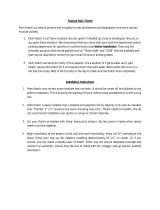
Installation of Universal model into a new home
Fig. 1 - Typical flush installation
Fit a Jetmaster cowl
(refer Fig. 8)
110 mm brickwork is adequate
if liners are used.
Moulded flue liner
Seal joint with fibreglass
insulation (supplied)
Fibreglass
insulation
Hot air
Smoke
Air inlet - leave open
Hearth -
by builder
Please read written instructions in conjunction with these diagrams.
3
Min: Height
3.6 Metres +
Back to
content page

Fig. 2 - Recessed installation using optional steel lintel and showing the
Superjet fan box
Weather top of chimney as
shown or fit Jetmaster cowl
(refer Fig. 8)
110 mm brickwork is adequate
if liners are used.
Moulded flue liner
Seal joint with fibreglass
insulation (supplied)
Fibreglass
insulation
Hot air
Max. recess 150 mm
Superjet fanbox and
air inlet cover plate
Smoke
Air inlet - leave open
Hearth -
by builder
Please read written instructions in conjunction with these diagrams.
4
Min: Height
3.6 Metres +
Back to
content page

5
Additional heat can be obtained from an existing fireplace by installing a
Jetmaster unit either from the regular range or custom-built to fit with a minimum
of building work.
2.1 Unit size and chimney flue
The size of Jetmaster firebox that can be installed into your existing
masonry fireplace is determined by the minimum dimensions of the
chimney flue.
Minimum flue areas are:
Model
2
500, 600 - 300 cm
2
700S, 700D - 366 cm
2
700 Double sided - 950 cm
2
850 - 510 cm
2
1050 - 730 cm
2
1200 - 1175 cm
2
1500 - 1475 cm
Before installing the firebox, ensure that the flue is of the correct area
throughout its entire length.
This can be done by lowering a torch (attached to strong cord) down the
chimney.
2.2 (a) Recess too large:
If the size of the firebox is smaller than the size of the recess, this can be
reduced by laying bricks at the sides and/or back and where necessary
between the top of the unit and the underside of the lintel or a plinth
can be constructed (refer Fig. 3). Leaving enough room for the
insulation.
(b) Recess too small:
The recess can be made deeper by removing the roll back and
smokeshelf. If too narrow cut away brickwork at sides and if height is
too low, remove the lintel and replace it at the required height.
NOTE: Allow 25 mm all round for the fibreglass insulation.
2.3 The two flue outlets must marry up with the existing chimney as indicated
in Fig. 3.
2.4 Any cracks or cavities in the recess must be repaired and sealed.
2.5 Tape the insulation to the back and sides of the Jetmaster and slide into the
recess, taking care not to snag the fibreglass insulation against the sides.
2.
Installation of Universal model into existing masonry fireplaces
Back to
content page

Installation of Universal model into existing masonry fireplaces
(Usually installed with bolt-on smoke gather removed)
Existing chimney gather
Hot air
Cement filler
Existing chimney breast
Fig. 3 - Section
Do not block
smoke outlets
Lintel
Max. recess 150 mm
Air lintel - leave open
Form plinth if required
Existing hearth
Smoke
Masonry fill for
spaces more than 75 mm
Please read written instructions in conjunction with these diagrams.
Fibreglass insulation (supplied)
NOTE: (a) Do not recess the frame of the firebox more than 150 mm.
(b) Ensure the smoke outlet openings are not obstructed.
(c) Air inlet at lower front of unit must not be obstructed.
2.6 Seal the firebox into position using masonry and mortar, ensuring that any
air leakage around the frame is eliminated. Non-combustible strips may be
required as indicated in Fig. 4. Mortar can be packed between the firebox
side and brickwork by hand through the damper opening.
2.7 Allow the masonry work to cure for a minimum of four days before
lighting a fire.
6
Back to
content page

Fig. 4 - Plan view
A
Fireplace recess slightly too
large (less than 75 mm) - pack
with extra layers of fibreglass
insulation
B
Fireplace recess too large
(more than 75 mm) - use
bricks to build up and reduce
size
Fibreglass
insulation
(supplied)
Infill strips of marble/stone/
tiles 10 mm overlap in front
or behind frame
Close gap with non-combustible
strip screwed to frame
Fireplace surround
Smoke outlets
Hearth
Please read written instructions in conjunction with these diagrams.
7
Back to
content page

3.1 Carefully cut a hole through the ceiling in a position away from any timber
beams or brandering, making sure that the opening is approx. 25 mm
larger than the steel flue. Use the ceiling escutcheon plate as a template
and add 12 mm all round to that dimension.
NOTE: To position the flue between the beams and brandering hammer a
nail downwards through the ceiling in the roof space.
3.2 Remove roof tiles in the immediate area or cut a similar hole through the
roofing material.
3.3 If a hearth is to be constructed (e.g. in a carpeted room), use a plumb line
from the centre of the hole in the ceiling to determine the position of the
hearth.
3.4 In the case of installing the Victor model, measure the position of the rear
securing bracket off the unit and fix the bracket to the wall by means of wall
plugs.
3.5 Position the fireplace unit and flue section.
NOTE: With the Hex and Lynx model, ensure that the butterfly damper is at
the base and rear of the flue.
3.6 The chimney flue must now be flashed at roof level with galvanised iron or
lead flashing. (Normally done by a plumber.) If a Rotating Hex model is
to be installed, the flashing top is circular in shape to allow the steel flue to
turn.
3.7 Push down the weathering collar over the flue until it covers the top of the
flashing by about 50 mm. Seal this against the flue using the black silicone
sealer (supplied).
3.8 Fit the cowl. In extremely windy areas it may be necessary to secure the
cowl to the flue by means of self-tapping screws.
3.9 If the flue is on more than one section it is advisable to seal the joint with
black silicone sealer (supplied) and secure the sections by means of self-
tapping screws. This is essential with the rotating Hex models.
3.10 Insulate the steel flue between the roof and ceiling with the insulation
material supplied, binding the fibreglass into position with light-gauge wire
meshing (also supplied).
3.11 Fix the escutcheon plate to the exposed ceiling to ensure a neat join where
the flue passes through.
8
3.
Installation of Hex, Lynx and Victor models
Back to
content page

3.12. Ensure flue is of sufficient length (see Fig. 10). Extra flue is available.
3.13. After installation paint exposed steel flue, cowl, etc above the roof line
with good quality external enamel to protect against corrosion. This will
require repainting from time to time.
3.14. With rotating Superjet Hex model, fireplace unit and flue rotate through
180E. Ensure that electrical connection is spiral flexible conduit.
3.15. Ensure rotating cowl turns freely and safety screw is engaged.
NOTE: THATCH OR TIMBER ROOFS
(a ) Where one of the above models is used in a thatch or timber-roofed
home, the space between the steel flue and the thatch should be
very well packed with the fibreglass insulation material. Please
ensure that the steel flue is thoroughly insulated. A galvanised
sleeve through the thatch should be provided for as shown in Fig. 6.
(b) It is advisable to have the top of the steel flue above the apex of the
roof. Do not fit fixed steel chimney cowl. If wind downdraught is
apparent, fit Jetmaster rotating cowl.
9
Back to
content page

Fig. 5 - Conventional roofs
Installation of Hex, Lynx and Victor models
Cowl (supplied)
Galvanised/lead flashing by
plumber to suit flue size and
pitch (see Fig 6 for rotating
Hex and thatched roofs).
Escutcheon plate
(supplied)
Seal with black silicone sealer
(supplied)
Seal joint at collar with black
silicone sealer (supplied) and
secure with self-tapping screws
if necessary
Secure fibreglass between
ceiling and roof with wire mesh
(supplied)
Fibreglass insulation (supplied)
Leave gap between ceiling
and chimney flue
Seal with black silicone sealer
(supplied) on inside at base of
flue (Hex model), or outside at
base of flue (Victor model).
Hearth by builder
Please read written instructions in conjunction with these diagrams.
10
Back to
content page

Fig. 6 - Thatched or Timber Roofs and Rotating Hex
With thatched or timber roof, omit
cowl (supplied) or fit rotating
Jetmaster cowl.
Galvanised/lead flashing
by plumber to suit size
andpitch (with rotating
Hex, top of flashing must
be circular)
Seal with black silicone sealer
(supplied)
Weathering collar (supplied)
Fibreglass insulation between
galvanised/lead sleeve and
chimney flue
T
h
at
c
h
Ra
r
fte
Galvanised/lead sleeve
50 mm larger than steel flue
Please read written instructions in conjunction with these diagrams.
11
Back to
content page

4.1 These models are usually installed on a raised hearth of non-combustible
material.
4.2 It is preferable to install these units into a masonry chimney with Jetmaster
moulded flue liners. Alternatively, a steel flue can be supplied at extra cost.
This is merely bolted against the wall by means of securing brackets. The
steel flue is then sealed at roof level in the same way as the Victor model,
referred to previously (see Fig. 5).
4.3 The steel flue elbow is designed for 110 mm or 220 mm wall thickness.
Select the correct end and fit to the unit.
4.4 Tape the fibreglass supplied to the back of the unit to reduce heat transfer
to the brickwork, Excess can be trimmed after installation.
4.5 Position the unit against the wall and prop the base to suit the height of
hearth required. Heron model requires air inlet to be built into hearth.
NOTE: (a) In the case of a facebrick wall the unit can be set against the
brickwork and the elbow built in.
(b) In the case of a plastered finish wall, the unit should be set slightly
proud of the stock brickwork and the plasterer should then plaster
up to and slightly behind the back of the unit.
4.6 The brickwork chimney can then be built ensuring that the internal size of
the flue is not less than the size of the elbow outlet throughout its length
(refer 1.2. chimney flues)
4.7 The top of the chimney stack must be weathered as shown or a Jetmaster
cowl fitted (refer Fig.8).
12
4.
Installation of Falcon and Heron models
Back to
content page

Please read written instructions in conjunction with these diagrams.
Installation of Falcon and Heron models
Fig. 7
Weather top of chimney as
shown or fit Jetmaster cowl.
(refer Fig. 8).
110 mm brickwork is adequate
if liners are used.
Moulded flue liner
Seal joint with fibreglass
insulation (supplied)
Correct side of elbow selected
to suit wall thickness
Fibreglass insulation
(supplied)
Hot air
o
k
e
S
m
Hearth by builder
Note: With Heron model air
inlet duct must be accommo-
dated in brickwork hearth.
13
Back to
content page

General
5.1 Please refer to figures 1 to 3 in addition to the written instruction.
5.2 The Jetmaster BIB unit should preferably be built in at the initial stages of
construction. Later installation of the BIB results in more and unnecessary
work and patching. When installing the 1500 or 1200 barbecue box, the
support pins for the lower door must remain free to move .
5.3 The face of the unit should not be recessed more than 150 mm behind the
face of the brickwork or plaster.
5.4 When installing the barbeque, choose a comfortable height for the grilling
surface, based on the height of the person who will usually be operating it.
If this is not known, a height of approximately 1000 mm to 1 200 mm from
finished floor level to the grilling surface is generally suitable.
5.5 It is preferable to support the 1500 and 1200 Super De Luxe models
primarily along their bottom side and back edges. If most of the weight of
these units is taken centrally, the base of the barbecue box may tend to bow
upwards.
5.6 If storage space is required beneath the barbecue box for chopped wood,
untensils, etc, the box should be supported on pre-pressed concrete lintels.
Positioned directly under and extending beyond the sides of the box to rest
on the supporting structure, these lintels will take the weight of the
brickwork chimney above. Refer to Fig. 8.
5.7 A grill is attached to the back plate of the motor box. Where feasible this
should be connected to an outside vent, such as a small pipe or similar. This
will provide a through draught, thereby reducing the build-up of excessive
heat in the motor box.
Insulation
5.8 In order to reduce heat transfer from the barbecue box to the surrounding
brickwork and provide an expansion joint to prevent cracking of masonry
or plaster once the unit is in use, your Jetmaster barbecue box and smoke
gather must be insulated with fibreglass. Care has to be taken that the
fibreglass does not get into the inside of the smoke gather where it will
disturb the smoke flow. Refer to Fig. 8.
5.9 Insulation material should not be compressed more than necessary. A
convenient material can be used to hold the fibreglass in place during
construction, if needed.
14
5.
Installation of Built-in Barbecues
Back to
content page

Please read written instructions in conjunction with these diagrams.
Fig. 8 - Installation of built-in barbecues
Fit Jetmaster cowl
(fixed or rotating)
110 mm brickwork is
adequate if liners are
used
Moulded flue liners
Cement in position
Fibreglass insulation
up to 200 mm above
top of smoke gather
Minimum 2000 mm
Pre-stressed concrete lintels
if storage beneath
required
Concrete lintel
(essential)
Electrical connection
Refer to Fig. 9 for
specific details
Seal joint with
fibreglass insulation
Smoke gather
5.10 Combustible materials should not be fitted closer than 200 mm to any
side of the barbecue box, or within 450 mm of the top of the barbecue
box, unless adequate provision is made to insulate such materials.
15
Back to
content page

Fig. 9 - Electrical connections
3 core stove wire
1000 De Luxe BIB
Plug point needed for
connecting
light duty motor
1500 & 1200 Super De Luxe BIB's
1000 De Luxe & 700 standard BIB's
3 core stove wire
220 V electrical source
2 lever switch box:
- One switch controls
light (standard)
- Second switch controls spit motor
(optional)
220 V motor
Leads from switch box
to motor
Spit
Spit
220 V electrical source
Please read written instructions in conjunction with these diagrams.
Electrical connection
5.11 Electrical work should only be carried out by a qualified electrician.
5.12 Please refer to Fig. 9 in addition to the written instructions.
5.13 All built-in models require a 220 V electrical connection for the light
fitting forming part of the outer barbecue box. The light fitting must be
earthed.
5.14 A light switch is needed for the 700 Std, 1000 Std ,1200 Std and 1000
De Luxe. Use insulated stove wire (supplied) to connect.
5.15 1500 and 1200 Super De Luxe models require internal wiring. A two
way switch inside the motor box is used to operate the light as well as the
220 V spit motor. The spit motor must be earthed.
5.16 For connecting each light fitting, a length of 3-core electrical stove wire is
supplied with each barbecue box. The sheath is fitted over the wire
where it passes through the wall of the barbecue box.
5.17 If the electrically-driven spit is incorporated into the 1000 De Luxe, a
suitable plug point to which the 220 V motor can be connected
should be provided.
16
5.18 The spit when fitted should never be turned by hand as you will strip the
gearing inside. To turn the spit turn the motor on and then off.
Back to
content page

Chimney flues and flue liners
5.19 Recommended flue sizes for the different models are:
1500 & 1200 Super De Luxe: 500 mm x 350 mm;
1000 De Luxe/Standard: 400 mm x 200 mm;
700 Standard: 300 mm x 200 mm
1200 Standard: 300mm x 300mm
5.20 Build the chimney flue slightly larger than smaller if you cannot
adhere to the recommended size. The internal flue size should under no
circumstances be smaller than the dimension of the smoke outlet at the
top of the gather.
5.21 The use of a Jetmaster moulded flue liner will ensure a perfect flue of the
correct size throughout. When such a liner is used, surrounding
brickwork can be reduced to 110 mm. Savings on brickwork and
plastering the inside of the chimney offset the costs of the liners.
5.22 The inside brickwork of the chimney needs to be plastered if a flue liner is
not used.
5.23 Ensure that the flue damper is erected the right side up.
5.24 The chimney flue should be at least 2 meters long to provide and
adequate draught, thereby preventing smoke from being expelled to the
front of the barbecue.
5.25 The level of the top of the chimney varies depending on roof type. Refer
to Fig. 10.
5.26 In the case of a thatch or timber-roofed home always ensure that the
chimney extends at least 1 m above the apex of the roof, irrespective of
the distance between chimney and roof apex. Only a Jetmaster rotating
cowl should be fitted. Never fit a fixed cowl in the case of a thatched roof.
5.27 A Jetmaster cowl (fixed or rotating) should be fitted to the top of the
chimney to prevent rain from entering the flue and causing unnecessary
corrosion of the barbecue box. This cowl also prevents downdraughts
and resultant smoking problems. In areas where there is high corrosion,
repaint the unit at least once a year with Jetmaster heat resistant paint.
5.28 In multiple installations, each barbecue unit should have its own flue
extending to the top of the chimney.
17
Back to
content page

Fig. 10 - Chimney heights
Chimney
(excl. cowl)
At least 1 m
Uppermost
roof level
If 600 mm or
less
If more than
600 mm
1 m
An opening or an
adjacent structure
If within 1,5 m
At least 1 m
Opening or adjacent structure
Chimney
(excl. cowl)
Chimney
(excl. cowl)
At least
600 mm
#
Roof pitch less than 10
#
Roof pitch of 10 or more
18
Back to
content page
/