Jetmaster JM Quadro User manual

Category
Fireplaces
Type
User manual

Jetmaster JM Quadro, your new outdoor wood fire and BBQ grill, is the perfect addition to your backyard. With its durable construction and innovative design, this versatile appliance offers endless possibilities for outdoor cooking and heating. Experience the joy of grilling your favorite foods, roasting marshmallows, or simply gathering around the温暖的fire on a chilly evening. Unleash your culinary creativity and embrace the great outdoors with Jetmaster JM Quadro.

Jetmaster JM Quadro, your new outdoor wood fire and BBQ grill, is the perfect addition to your backyard. With its durable construction and innovative design, this versatile appliance offers endless possibilities for outdoor cooking and heating. Experience the joy of grilling your favorite foods, roasting marshmallows, or simply gathering around the温暖的fire on a chilly evening. Unleash your culinary creativity and embrace the great outdoors with Jetmaster JM Quadro.

IMPORTANT: Read all instructions carefully before starting installation. Failure to follow these instructions
may result in afire hazard and will void the warranty.
Due to continued product improvement, The Fireplace Ltd reserves the right to change product specifications without prior notification.
Please check to ensure you have the latest installation instructions.
TYPICAL JETMASTER IN-BUILT TIMBER FRAME & MASONRY
FIREBOX INSTALLATION INSTRUCTIONS FOR
QUADRO OUTDOOR WOOD FIRE & BBQ GRILL
08/2022 1
CONTENTS
Before you start - IMPORTANT…………………………
Firebox Dimensions ………………………………………
Timber Cavity Framing Dimensions ………………......
Timber Frame Plan & Section ………………………….
Hebel Cell Diagram ………………………………………
Front Face Margin ……………………………………...
Firebox Installation……………………………………….
Masonry Cavity Plan & Section …………………….…
Firebox Installation and Margins………………….…….
Flue Installation …………………………………………..
Flue Penetration & Chimney Chase Air Ventilation…..
Floor Protector requirements …………………………….
Hebel Cut Out Schedule…………………………….
3
4
4
5
6
7
8
9
10
11
12
13
14
2
HeadOffice &Showroom
12 Tawari St, Mt Eden,Auckland
Ph: 09 623 6990
thefireplace.co.nz
AS/NZS2918:2001 GENERAL NOTES SOLID FUEL
THE APPLIANCE AND FLUE SYSTEM SHALL BE INSTALLED IN ACCORDANCE WITH AS/NZS2918:2001
AND THE APPROPRIATE REQUIREMENTS OF THE RELEVANT BUILDING CODE OR CODES.
MIXING OF APPLIANCE OR FLUE SYSTEM COMPONENTS FROM DIFFERENT SOURCES OR
MODIFYING THE DIMENSIONAL SPECIFICATION OF COMPONENTS MAY RESULT IN HAZARDOUS
CONDITIONS. WHERE SUCH ACTION IS CONSIDERED, THE MANUFACTURER SHOULD BE
CONSULTED IN THE FIRST INSTANCE.
CRACKED AND BROKEN COMPONENTS, e.g. GLASS PANELS OR CERAMIC TILES, MAY RENDER THE
INSTALLATION UNSAFE.
DO NOT USE FLAMMABLE LIQUIDS OR AEROSOLS TO START OR REKINDLE THE FIRE OR IN THE
VICINITY OF THIS APPLIANCE WHEN OPERATING.
DO NOT STORE FUEL WITHIN HEATER INSTALLATION CLEARANCES.
WHEN OPERATING THIS APPLIANCE AS AN OPEN FIRE USE A FIRE SCREEN.
THIS APPLIANCE SHOULD BE MAINTAINED AND OPERATED AT ALL TIMES IN ACCORDANCE WITH
THESE INSTRUCTIONS.
USE OF SOME TYPES OF PRESERVATIVE-TREATED WOOD AS A FUEL CAN BE HAZARDOUS.
IF INSTALLED IN ACOMMERCIAL SETTING ASACRIFICIAL PLATE MUST BE FITTED TO THE BACK
OF THE FIRE TO COMPLY WITH JM FIREBOX WARRANTY CONDITIONS.
THE FLUE SYSTEM SHOULD BE CLEANED EVERY 12 MONTHS.
AS/NZS2918:2001 GENERAL NOTES SOLID FUEL
AS/NZS5601:2013GENERAL NOTES GAS
THE JETMASTER UNIT IS TO BE INSTALLED BY ACERTIFIED FIREPLACE
INSTALLER , APPROVED NZHHA INSTALLATION TECHNICIAN
IMPORTANT
3
CAVITY FRAMING A B C D E F
1050 1400 800 500 850 2 x 160 dia. or 2 x (100 x200) 1275 height of Hebel cell
Timber frame-out with 75mm Hebel cell on a steel base.
IMPORTANT: If the firebox is raised it must be placed on
top of a 75mm Hebel panel which is placed on top of a
steel structure or masonry blocks. Height of 500mm is
recommended.
A TIMBER BASE IS NOT ACCEPTABLE
Please note that these dimensions (based on Hebel
Block margins) are the absolute minimum sizes - widths
(A & B) maybe increased if desired.
Table 1
TIMBER FRAME DIMENSIONS
JETMASTER FIREBOX DIMENSIONS
4
Note: All dimensions are in (mm)
min 2 x 160mm dia. or equal square or rectangle shaped
air vents to be wall mounted
Hebel
Maximum 100mm recess
Floor Protector (refer to Table 4)
800mm + recess
value (refer to
Table 2)
1400mm
Non Combustible material
(e.g Promatect H)
100
min
75
Flue Pipe Casing
S/S Flue Pipe
Hebel
Rock Wool
Insulation
Hebel Block
Non Combustible material
(e.g Promatect H)
Maximum 100mm recess
Secure firebox with 2 x12mm
dynabolts for earthquake
retraints
Maintain the air intake
unobstructed
Floor Protector
C(see Table 2)
Note: All external air vents must be bird & rodent
proofed with permanently fixed screen
Rebate to suit tiles or other non
combustible material on Floor
Protector
It is important to ensure the Jetmaster firebox is seated at the
required finished Floor Protector level
see Table 5
min 25mm from flue pipe casing to combustible material
25 25
Drawing Not To ScaleDrawing Not To Scale
Optional
Finishing:
Stone, Brick,
Plaster on
Brick
min 2 x 160mm dia
or equal square or
rectangle shaped air
vents to be wall
TIMBER FRAME CROSS SECTION -RECESS
DETAIL
TIMBER FRAME PLAN -RECESS
DETAIL
5
Note:If the appliance is exposed not under protective cover please recess the appliance
.Min =40mm/Max recess =100mm
Rock Wool
Insulation
(Glue rock wool
using fire cement
to the firebox &
gather)
6
All Hebel Block margins have been made to fit firebox timber frame trim out dimensions (see
Hebel cut-out plan). Suggested method to cut Hebel Block -skill saw fitted with masonry
blade.
Under no circumstance is the width of the vertical margin legs to be less than 150mm and the
height of the margin lintel to be less than 300mm
Where aboard finish is required around the fire, ensure allowance is made to place non combustible
internal wall lining (eg:Promatect H) to cover the extent of the Hebel panel surround (shown shaded).
Directly touching the firebox with any board or plaster finish will cause cracking from heat expansion.
Allow 2mm minimum space away from the firebox.
J et ma st er
Margin Lintel
min 300mm
Timber Framing
75mm min Hebel Block or
100mm Concrete
Note:Ensure allowance
made for firebox to sit
on top of finished Floor
Protector level
Margin leg to be no less than
150mm wide
Bond Hebel Block together using appropriate adhesive eg: Gorilla Grip or
similar (non-solvent based) &secure with screws for added strength
MARGIN SET
Non Combustible Board
7
Refer to the minimum framing dimensions as per table 2. Allow atemporary lintel height (see table
2‘B’) from the finished floor protector level until the firebox and flue system is installed.Install front
nogs on edge to increase chimney chase dimension.
Ensure suitable air vents (2 x 160mm diameter or equivalent) in place to vent firebox space -these
maybe located in the floor or in the side wall space.Ensure vents must be bird and vermin proofed.
FIREBOX INSTALLATION
All dimensions shown for the framing trim out and Hebel cell are based on a maximum
frontal clearance between the timber framing and the rear of the firebox fascia, being not
more than 15mm.
Locate floor protector in trim out cavity. If on a concrete floor, suggest a mortar screed to the
underside of the floor protector. If on a wooden floor, screw or dynabolt in place.
Locate stud openings on both sides.
Position and ensure a strip of glass rock wool insulation is between the inner hebel leg face and
the firebox. Nail through stud into hebel leg to secure in place.
Locate and position firebox, fit and seal gather in cavity. Earthquake restraints may be
positioned by drilling through firebox into the floor protector, in a position midway beneath the
log-pan. Two 12mm dynabolts or similar will suffice. Do not over tighten and deform firebox.
Attach rock wool to the sides & back of the firebox and gather. DO NOT BLOCK OFF the air
entry between the inner flue pipe and flue pipe casing or the air circulation between the vent
holes in the cavity.
Once the flue system is installed, place a minimum 300mm hebel block over the front face
of the firebox and gather.
Ensure the hebel block does not rest on top of the firebox. A Lintel Bar may be required.
TIMBER FRAMING PREPARATION
8
IMPORTANT:The appliance must be located aminimum of 1200mm away from
combustible adjacent walls (e.g. exterior of house)
The appliance, gather, flue and Hebel panel weighs approx.400kg.Ensure the base
structure can withstand this load.
MODEL A B Temporary Lintel CDE -Vents
1050 1150 700 1200 100 860 2 x 160dia. or 2 x 100x 200
Table 2
MASONRY MINIMUM CAVITY SIZE
Fig. 11
PLAN -RECESS DETAIL
min. 25mm clearance 25
25 min. 25mm clearance
700mm + recess
Masonry or Hebel block
minimum ‘A
Refer to Table 4 for Floor Protector dimension
RECESS REQUIRED (40mm Min. 100mm Max)
Allow gas line into
firebox
(if applicable)
Air Vent
Refer to Table 5 for Floor
Protector dimension
Air Vent
min. 2 x 100 x 50mm or 80mm diam
wall of floor mounted air vents
Drawings Not To Scale
9
Note: If the appliance is exposed not under protective cover please recess the appliance .
Min =40mm/Max recess = 100mm. Add recess dimension to B dimension in Table 2.
100
700mm + recess
Allow 5mm gap
around all four
sides of the firebox
to fit Stainless
Steel cover & allow
for firebox
expansion
RECESS REQUIRED
40mm Min.
-100mm Max recess
CROSS SECTION
min 2 x 160mm dia. or equal square or rectangle shaped
air vents to be wall mounted
FIREBOX INSTALLATION
1. Locate and position firebox, fit and seal gather in cavity using fire cement (exhaust cement) and
bolts (supplied), to the firebox.
2. Note:Pop rivet back of gather to firebox if required (refer to Cross Section).Earthquake
restraints may be positioned by drilling through firebox into the floor protector, in aposition
midway beneath the log-pan.Two 6mm dynabolts or similar will suffice.Do not over tighten and
deform firebox.
2. Attach rock wool (supplied) to the sides of the firebox and gather (using fire cement).
3. DO NOT BLOCK OFF the air entry between the inner flue pipe and flue pipe casing or the air
circulation between the vent holes in the cavity.
3. Refer to Table 4, for minimum hearth size.
A minimum 75mm thick Floor protector is only required if finished surface is combustible e.g:timber.
Please note that these dimensions (based on Masonry margins) are the absolute minimum sizes -
widths (A & B) maybe increased if desired. If you intend on recessing the firebox, please add the
recess value to Dimension ‘B’.
WARNING: Minimum cavity sizes leave NO MARGIN FOR ERROR . If the cavity is larger than
minimum dimensions (A & B) close up the lateral sides using Hebel block, concrete block
or similar (do not use any combustible material).
Refer to Table 2 for the minimum cavity dimensions and temporary lintel height measurements,
until the firebox and flue system is installed. Note: Temporary lintel height is measured from
finished floor protector level.
Ensure suitable air vents (min. 2 x 160mm diameter or equivalent) in place to vent firebox space -
these maybe located in the rear or in the side wall space; make allowance (min. 2 x 160mm
diameter or equivalent) at the top of the chimney chase, Pg. 13. Ensure vents are bird and vermin
proofed.
CAVITY PREPARATION
Allow 5mm gap between plaster and flange to
ensure stainless steel cover can be fitted to the
box. DO NOT PLASTER OVER THE FLANGE.
Jetmaster
Flange
10
1. Install first length of flue pipe crimped end down, inside gather collar. Rivet flue pipe in 3 places around
gather collar. Place bottom flue spider bracket around gather flue pipe collar, secure in position by
tightening up coach bolt/screw (supplied). Seal flue with fire
2. Install second length of the flue pipe crimped end down and fix by riveting in at least 3 places around the
flue pipe joint.
3. Install first length of the flue pipe casing by positioning on installed bottom flue spider bracket crimped
end up.
4. Position flue spacer at the flue pipe joint.
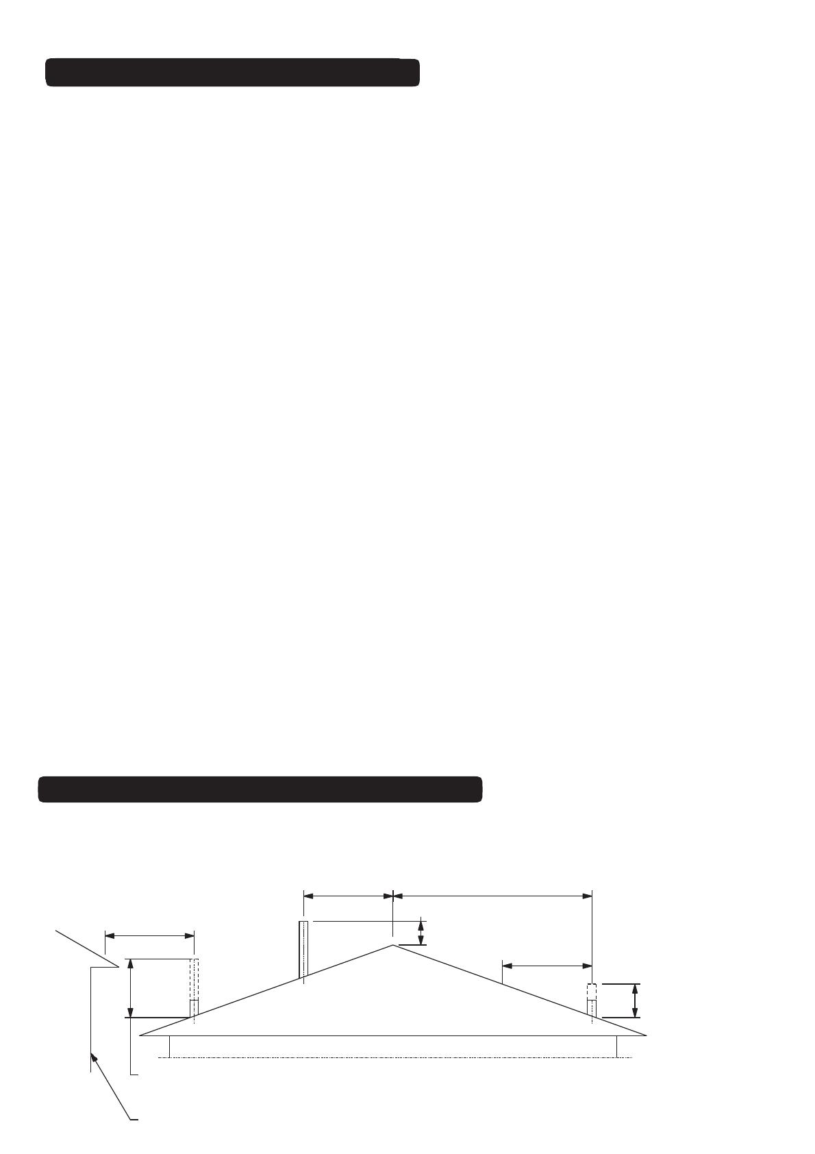
5. Repeat steps 1 - 4 to the required flue height. As per AS/NZS2918:2001 4.9.1
a. “the flue pipe shall extend not less than 4.6m above the top floor protector”.
b. “the minimum height of the flue system within 3m distance from the highest point of the roof
shall be 600mm above that point”.
c. “the minimum height of a flue system further than 3m from the highest point of the roof shall be” a
minimum “1000mm above roof penetration”.
d. “no part of any building lies in or above a circular area described by a horizontal radius of 3m
about the flue system exit”.
6. The last length of flue pipe needs to extend past the flue pipe casing by at least 150mm or flush with
the top of the casing cover spigot when fitted - sizing/measuring and cutting down should be carried out
prior to the flue pipe casing being fitted over the flue pipe.
7. Before fitting casing cover, place the spider in opposition with the spider post facing down between the
flue pipe and flue pipe casing. Secure spider in position. Place the casing cover over the flue pipe, press
down firmly onto the spider. Check airway around the casing cover is clear, then secure in position
using three stainless steel rivets.
8. Fit cowl to top of flue - DO NOT RIVET IN POSITION. In high wind areas, it is recommended that the
cowl be secured in position with a stainless steel self tapping screw, this will enable the cowl to be
removed for cleaning. Discuss Bird Proofing needs with your installer.
9. If flue is concealed in a chase, allow for air vents (2 x 80mm diam. or equivalent) at the highest possible
point on the chimney chase or alternatively, allow a min 25mm air space between the casing cover spigot
and the outer casing. Refer to pg. 12.
FLUE INSTALLATION SOLID FUEL
3000
or less
3000
More than 3000
600 min.
3000
increase from 1000mm
minimum until clear within
3000mm of flue top
increase as necessary
until nothing within
3000mm of flue top
Any nearby structure
As per AS/NZS 2918:2001 4.9.1 Fig 4.9
MINIMUM HEIGHT OF FLUE SYSTEM EXIT
Note:2xflue lengths are supplied as aminimum for free standing outdoor built installations.If
the outdoor fire structure is attached to the house the flue will need to be extended and meet
the following requirements;
11
50 25
25
Air Ventilation Through Chimney Chase Air Ventilation Through Top Flashing
Drawings Not To Scale
Non combustible material
Hebel Block or
12 mm Promatect H board
or similar under the flashing
Oversized casing cover
is necessary
150 mm
minimum
150 mm
minimum
Spigot flashing to suit
flue pipe casing
Drip
Line Drip
Line
flue pipe
flue pipe casing
25
25
Typical Cowl
Casing Cover
Air Gap
Top Spider
Approved
Flashing
Air
Vents
min 2 x 80mm dia
or equal square or
rectangle shaped
area
min 25mm gap between flue
pipe casing &combustible
surface
EXTERNAL REQUIREMENTS SOLID FUEL
Refer to AS/NZS2918:2001; 4.9.1
Note:All external air vents &
ceiling penetrations must be bird
&rodent proofed with permanently
fixed screens
Drawing Not To Scale
Minimum 25mm gap between
flue pipe casing
&combustible surface
Air Vent
min 2 x 80mm diam. or equal square or rectangle shaped area
Promina Board or similar
Hebel Block
Note: All external air vents &ceiling penetrations must be bird &rodent proofed with permanently fixed screens
FLUE PENETRATION
CHIMNEY CHASE AIR VENTILATION
12
X
Y
X
Y
Flue Pipe
Min. 25mm Clearance
Min. 25mm Clearance
Flue Pipe Casing
MODEL FLUE SYSTEM MINIMUM TRIM OUT DIMENSION
X(min) Y(min)
1050 300/400 450 450
Table 3
Dimensions in mm
Note: Aminimum 25mm clearance from flue pipe casing to combustible material must be maintained.
AMinimum clearance of 200mm above Heat Shield must be maintained.
CHIMNEY CHASE MINIMUM TRIM OUT
MODEL A B C
Floor Level 1400
800
75
Raised 500mm 1400
1000
75
A
B
C
*A minimum 75mm thickness refers only to Hebel Block for solid fuel installations. Minimum 100mm thickness
required if poured concrete
.
Table 4
MINIMUM FLOOR PROTECTOR SIZE
13
14
  • Page 1 1
  • Page 2 2
  • Page 3 3
  • Page 4 4
  • Page 5 5
  • Page 6 6
  • Page 7 7
  • Page 8 8
  • Page 9 9
  • Page 10 10
  • Page 11 11
  • Page 12 12
  • Page 13 13
  • Page 14 14

Jetmaster JM Quadro User manual

Category
Fireplaces
Type
User manual

Jetmaster JM Quadro, your new outdoor wood fire and BBQ grill, is the perfect addition to your backyard. With its durable construction and innovative design, this versatile appliance offers endless possibilities for outdoor cooking and heating. Experience the joy of grilling your favorite foods, roasting marshmallows, or simply gathering around the温暖的fire on a chilly evening. Unleash your culinary creativity and embrace the great outdoors with Jetmaster JM Quadro.

Ask a question and I''ll find the answer in the document

Finding information in a document is now easier with AI