Page is loading ...

NOTE: DIAGRAMS & ILLUSTRATIONS ARE NOT TO SCALE.
1
NOTE: DIAGRAMS & ILLUSTRATIONS ARE NOT TO SCALE.
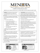
ASSEMBLY AND INSTALLATION INSTRUCTIONS FOR SURROUND KITS
FOR USE ON CONTEMPORARY LINEAR VIEW DIRECT-VENT GAS FIREPLACES
P/N 900079-07
Rev. B 01/2016
HEARTH PRODUCTS
KITS AND ACCESSORIES
SURROUND KIT
FOR CONTEMPORARY LINEAR GAS FIREPLACES
[MODEL NUMBERS SIRIUS42TEN/P, SIRIUS54TEN/P, DRL3042TEN/P, AND DRL3054TEN/P]
Gas Shutoff
Valve Door
Barrier
Mounting
Bracket
(bottom)
Figure 1 - Linear View Surround
Size Finish Flange Size Cat. No.
42 in. Surround
Black 1” Return Flange F2261
Stainless Steel 1” Return Flange F2263
Black 1-1/2” Return Flange F2265
Stainless Steel 1-1/2” Return Flange F2267
54 in. Surround
Black 1” Return Flange F2260
Stainless Steel 1” Return Flange F2262
Black 1-1/2” Return Flange F2264
Stainless Steel 1-1/2” Return Flange F2266
Table 1 - Surround Kits
REQUIRED TOOLS
• 3/8 in. Hex-head nut driver
• Safety glasses
• Protective work gloves
NOTICE
• READ ALL STEPS BEFORE STARTING INSTALLATION.
• LEAVE THESE INSTRUCTIONS WITH THE APPLIANCE.
• All warnings, precautions, and instructions in the Installation and
Operation Manual provided with the appliance also apply to these
instructions.
• If you encounter any problems, need clarification of these instructions,
or are not qualified to properly install this kit, contact your local
distributor or dealer.
KIT CONTENTS
• Stainless steel surround
• Gas line extension and bracket
• Top surround section (1)
• Bottom surround section (1)
• Side surround sections (2)
• Side support bars (2)
• #10-16 X 3/8 hex-head sheet metal screws (17)
• Gas line assembly brackets (4)
• Barrier mounting brackets (4) (not shown)
• These instructions
RIGHT Side
Surround Section
(rear view)
LEFT Side
Surround Section
(rear view)
Side Support Bars
Top Surround Section (rear view)
Bottom Surround Section (rear view)
Figure 2 - Kit Contents
DANGER
HOT GLASS WILL CAUSE BURNS.
DO NOT TOUCH GLASS UNTIL COOLED.
NEVER ALLOW CHILDREN TO TOUCH GLASS.
• Install only when fireplace is OFF and COLD.
• Fireplace surfaces get EXTREMELY HOT!
• The glass on the front of the fireplace reaches EXTREMELY HIGH
temperatures and can cause severe burns if touched. Even after
the gas is turned off, fireplace surfaces remain extremely hot.
• A barrier designed to reduce the risk of burns from the hot viewing
glass is provided with this appliance and shall be installed for the
protection of children and other at-risk individuals.

INNOVATIVE HEARTH PRODUCTS • LINEAR VIEW GAS FIREPLACES • SURROUND KIT
2
NOTE: DIAGRAMS & ILLUSTRATIONS ARE NOT TO SCALE.
GENERAL INFORMATION
This document contains instructions for assembling and
installing the enclosed surround for use with Contemporary
Linear direct-vent gas fireplaces manufactured by Innovative
Hearth Products.
NOTE: For easier installation, remove the fireplace front door
before installing the surround. Refer to the Installation and
Operation Manuals (PN 900079-00 and 900079-02) for more
information.
NOTE: Make sure you have the correct kit and all required
parts before starting installation.
INSTALLATION INSTRUCTIONS
NOTE: Ensure the work surface is free of debris that
may damage the surround finish. Any such DAMAGE
IS NOT COVERED by the manufacturer's warranty.
When the work surface is ready, peel the clear
protective plastic film from all surround sections.
Step 1. Lift barrier up from mounting brackets and pull away
from fireplace. Remove clean-face frame (Figure 3).
NOTE: The side support bar has small notches that
face the front of the surround.
Figure 3 - Clean Face Frame (Shaded)
Step 2. Lay out the parts of the surround face down. Arrange
the parts as shown in Figure 4 (the surround must be
assembled from the back side).
Figure 4 - Lay Out the Surround Parts
Step 3. Insert the side support bar under the lip of the edge of
the side surround section, as shown in Figure 5.
Figure 5 - Insert Side Support Bar
Step 4. Slide the upper end of the side support bar under the
lip of the top surround section (Figure 6).
Figure 6 - Align Side Support Bar with Surround Section
Step 5. Align the two holes in the upper lip of the side
surround section with the corresponding holes in the
top surround section, and secure using two (2) of the
provided #10-16 x 3/8 hex-head screws (Figure 7).
Figure 7 - Attach Side Support to Surround Section
Step 6. Repeat Step 2 through Step 5 for the other side of the
surround.
Step 7. Attach the bottom surround section in the same
manner, and secure using four (4) of the provided
#10-16 x 3/8 hex-head screws (2 per side)

3
INNOVATIVE HEARTH PRODUCTS • LINEAR VIEW GAS FIREPLACES • SURROUND KIT
NOTE: DIAGRAMS & ILLUSTRATIONS ARE NOT TO SCALE.
Step 8. Carefully attach the assembled surround to the
fireplace using nine (9) of the provided #10-16 x 3/8
hex-head screws (3 at the top and 6 at the bottom),
take care not to scratch or damage the finish on the
surround. See Figure 9.
Step 9. (Optional) Installing the gas shut-off valve;
a. Pull gas flex line out from inside, beneath fireplace
floor.
b. Place shut-off valve in valve bracket, threading flex
line through gap in back.
c. Use coupler to attach additional flex line to shut-off
valve.
d. Bend up tab on the side of valve bracket to hold
shut-off valve in place (Figure 8).
e. Attach valve bracket to unit with two screws.
f. Attach shut-off valve to incoming gas line with field-
supplied coupler.
Gap
(thread
flex
gas line
here)
Back Side
Tab (bend up
to hold valve)
Figure 8 - Gas Shutoff Valve Bracket
Step 10. Place unit in wall framing.
NOTE: The provided non-combustible fiber board
may be faced with any NON-combustible finish
material appropriate for use (brick, tile, stone, high-
temperature paint, etc.). For painted wall finish, use
two (2) coats of quality primer and high-temperature
paint on provided fiber board.
Step 11. Secure nailing flanges to wall framing.
Step 12. Secure heat shield to top front of unit with two screws.
NOTE: Refer to the Instruction Manual (P/N 900079-00)
for finishing details.
Step 13. Place insulation flat across the top of the fireplace
lengthwise behind heat shield.
Step 14. Cut noncombustible fireboard to size and install flush
with top of frame pieces.
Step 15. Finish out wall with 1/2" finishing materials – paint
with high-temperature paint, etc.
Step 16. Attach surround in frame using screws a minimum of
six at specified locations (Figure 9).
Figure 9 - Attach the Surround to the Fireplace
Step 17. Install barrier mounting brackets on side of surround.
Step 18. If removed, reinstall door and secure with three
screws.
Step 19. Install Gas Shutoff Valve Door (Figure 1).
Step 20. Install barrier on barrier mounting brackets.

INNOVATIVE HEARTH PRODUCTS • LINEAR VIEW GAS FIREPLACES • SURROUND KIT
4
P900079-07
Printed in U.S.A. © 2015 Innovative Hearth Products
P/N 900079-07 Rev. B 01/2016
IHP reserves the right to make changes at any time, without notice, in design, materials,
specifications, and prices, and also to discontinue colors, styles, and products. Consult your
local distributor for fireplace code information.
1508 Elm Hill Pike, Suite 108 • Nashville, TN 37210
/