Page is loading ...

1
NOTE: DIAGRAMS AND ILLUSTRATIONS ARE REPRESENTATIVE AND ARE NOT DRAWN TO SCALE.
www.IHP.US.com
P900253-00
ASSEMBLY AND INSTALLATION INSTRUCTIONS FOR SURROUND KITS
FOR USE ON CONTEMPORARY LINEAR VIEW DIRECT-VENT GAS FIREPLACES
P/N 900253-00 Rev. NC 10/2014
HEARTH PRODUCTS
KITS AND ACCESSORIES
SURROUND KIT
FOR CONTEMPORARY LINEAR VIEW GAS FIREPLACES
[MODEL NUMBERS SIRIUS42TEN/P, SIRIUS54TEN/P, DRL3042TEN/P AND DRL3054TEN/P]
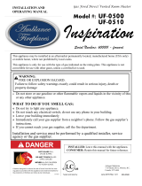
Figure 1: Contemporary Linear View Surround
Size Finish Cat. No. Model No.
42 in. Surround Black Satin H8654 LDV42-SB
54 in. Surround Black Satin H8652 LDV54-SB
Table 1: Surround Kits for Contemporary Linear View Gas
Fireplaces
KIT CONTENTS
• Top surround section (1)
• Bottom surround section (1)
• Side surround sections (2)
• Side support bars (2)
• #10-16 x 3/8 Hex-head sheet metal screws (17)
RIGHT Side
Surround Section
(rear view)
LEFT Side
Surround Section
(rear view)
Side Support Bars
Top Surround Section (rear view)
Bottom Surround Section (rear view)
Figure 2: Kit Contents
REQUIRED TOOLS
• 3/8 in. Hex-head nut driver
• Safety glasses
• Protective work gloves
GENERAL INFORMATION
This document contains instructions for assembling and
installing the enclosed surround for use with Elite™ Linear View
direct-vent gas fireplaces manufactured by Innovative Hearth
Products.
NOTICE
•READ ALL STEPS BEFORE STARTING INSTALLATION.
•LEAVE THESE INSTRUCTIONS WITH THE APPLIANCE.
•All warnings, precautions, and instructions in the Installation
Instructions and Care and Operation Instructions provided with the
appliance also apply to these instructions.
•If you encounter any problems, need clarification of these
instructions,orarenotqualiedtoproperlyinstallthiskit,contact
your local distributor or dealer.
NOTE:For easier installation, remove the fireplace front
door before installing the surround. Refer to the Care and
Operation Instructions (PN 900079-00) for more information.
NOTE: Make sure you have the correct kit and all required
parts before starting installation.
INSTALLATION INSTRUCTIONS
NOTE: Ensure the work surface is free of debris that
may damage the surround finish. Any such DAMAGE
IS NOT COVERED by the manufacturer's warranty.
When the work surface is ready, peel the clear
protective plastic film from all surround sections.
Step 1. Lay out the parts of the surround face down. Arrange
the parts as shown in Figure 3 (the surround must be
assembled from the back side)
Step 2. Insert the side support bar under the lip of the edge of
thesidesurroundsection,asshowninFigure 4.
NOTE: The side support bar has small notches that
face the front of the surround.
Step 3. Slide the upper end of the side support bar under the
lip of the top surround section (Figure 5).
DANGER
HOT GLASS WILL CAUSE BURNS.
DO NOT TOUCH GLASS UNTIL COOLED.
NEVER ALLOW CHILDREN TO TOUCH GLASS.
• Install only when fireplace is OFF and COLD.
• Fireplace surfaces get EXTREMELY HOT!
• The glass on the front of the fireplace reaches EXTREMELY HIGH
temperatures and can cause severe burns if touched. Even after the
gas is turned off, fireplace surfaces remain extremely hot.
• Keep children away from an operating fireplace. Closely supervise
children in any room where a fireplace is operating to prevent contact
with glass.

INNOVATIVEHEARTHPRODUCTS•LINEARVIEWDIRECT-VENTGASFIREPLACE•REQUIREDANDOPTIONALACCESSORIES
2
Printed in U.S.A.
© 2014 INNOVATIVE HEARTH PRODUCTS, LLC
NOTE: DIAGRAMS AND ILLUSTRATIONS ARE REPRESENTATIVE AND ARE NOT DRAWN TO SCALE.
P/N 900253-00 Rev. NC 10/2014 P900253-00
1508 Elm Hill Pike, Suite 108
Nashville, TN 37210
IHP.US.com
Figure 3: Lay Out the Surround Parts
Figure 4: Insert Side Support Bar
Step 4. Align the two holes in the upper lip of the side
surround section with the corresponding holes in the
topsurroundsection,andsecureusingtwo(2)ofthe
provided #10-16 x 3/8 hex-head screws (Figure 6).
Step 5. Repeat Step 1 through Step 4 for the other side of
the surround.
Step 6. Attach the bottom surround section in the same
manner,andsecureusingfour(4)oftheprovided
#10-16 x 3/8 hex-head screws (2 per side)
Figure 5: Align Side Support Bar with Surround Section
Figure 6: Attach Side Support to Surround Section
Step 7. Carefully attach the assembled surround to the
fireplace using nine (9) of the provided #10-16 x 3/8
hex-headscrews(3atthetopand6atthebottom),as
shown in Figure 7,takecarenottoscratchordamage
the finish on the surround.
Step 8. Attach the Modesty Panel with three magnets (see
Figure 8).
Figure 7: Attach the Assembled Surround to the Fireplace
Figure 8: Placing Magnets for Modesty Panel
/