
Digital Multi Switcher
MSD-62 Series
MSD-6203/MSD-6204
<User Guide>
Ver.2.6.0
⚫ Thank you for choosing our product.
⚫ To ensure the best performance of this product, please read this user guide fully and carefully before using
it and keep this manual together with the product for future reference as needed.
IDK Corporation

MSD-62 Series User Guide
2
Trademarks
⚫ HDBaseT™ and the HDBaseT Alliance Logo are trademarks of the HDBaseT Alliance.
⚫ The terms HDMI and HDMI High-Definition Multimedia Interface, and the HDMI Logo are trademarks or
registered trademarks of HDMI Licensing Administrator, Inc. in the United States and other countries.
⚫ SDVoE™ and SDVoE logo are trademarks of SDVoE Alliance.
⚫ Audinate® is a registered trademark of Audinate Pty Ltd. Dante® is a registered trademark of Audinate Pty
Ltd.
⚫ All other company and product names mentioned in this document are either registered trademarks or
trademarks of their respective owners. In this document, the “®” or “™” marks may not be specified.
⚫ ©2018 IDK Corporation, all rights reserved.

MSD-62 Series User Guide
3
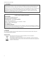
Before reading this manual
⚫ All rights reserved.
⚫ Some information contained in this User guide such as exact product appearance, diagrams, menu
operations, and so on may differ depending on the product version.
⚫ This User guide is subject to change without notice. You can download the latest version from IDK’s
website at: www.idkav.com
The reference manual consists of the following two volumes:
■ User guide (this document):
Provides explanations and procedures for operations, installation, connections among devices,
I/O adjustment and settings.
■ Command guide: Please download the command guide from the website above.
Provides explanations and procedures for external control using RS-232C and LAN communications.

MSD-62 Series User Guide
4
FCC STATEMENT
Note: This equipment has been tested and found to comply with the limits for a Class A digital device,
pursuant to part 15 of the FCC Rules. These limits are designed to provide reasonable protection against
harmful interference when the equipment is operated in a commercial environment. This equipment
generates, uses, and can radiate radio frequency energy and, if not installed and used in accordance with
the instruction manual, may cause harmful interference to radio communications. Operation of this
equipment in a residential area is likely to cause harmful interference, in which case the user will be
required to correct the interference at his own expense.
(Class A)
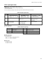
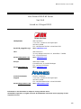
Supplier’s Declaration of Conformity
47 CFR § 2.1077 Compliance Information
Unique Identifier
Type of Equipment: Digital Multi Switcher
Model Name: MSD-6203, MSD-6204
Responsible Party – U.S. Contact Information
Company Name: IDK America Inc.
Address: 72 Grays Bridge Road Suite 1-C, Brookfield, CT 06804
Telephone number: +1-203-204-2445
URL: www.idkav.com
FCC Compliance Statement
This device complies with Part 15 of the FCC Rules. Operation is subject to the following two conditions: (1)
This device may not cause harmful interference, and (2) this device must accept any interference received,
including interference that may cause undesired operation.
(FCC SDoC)
CE MARKING
This equipment complies with the essential requirements of the relevant European health, safety and
environmental protection legislation.
WEEE MARKING
Waste Electrical and Electronic Equipment (WEEE), Directive 2002/96/EC
(This directive is only valid in the EU.)
This equipment complies with the WEEE Directive (2002/96/EC) marking requirement.
The left marking indicates that you must not discard this electrical/electronic equipment in
domestic household waste.

MSD-62 Series User Guide
5
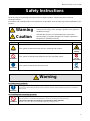
Safety Instructions
Read all safety and operating instructions before using this product. Follow instructions and heed
warnings/cautions.
Instructions and warnings/cautions for all products are provided. Some of them may not be applicable to your
product.
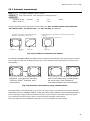
Warning
Indicates the presence of a hazard that may result in death or
serious personal injury if the warning is ignored or the product is
handled incorrectly.
Caution
Indicates the presence of a hazard that may cause minor
personal injury or property damage if the caution is ignored or
the product is handled incorrectly.
Symbol
Description
Example
Caution
This symbol is intended to alert the user. (Warning and caution)
Hot surfaces
Caution
Prohibited
This symbol is intended to prohibit the user from specified actions.
Do not
disassemble
Instruction
This symbol is intended to instruct the user.
Unplug
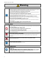
Warning
For lifting heavy products:
Instruction
● Lifting must be done by two or more personnel.
To avoid injury: When lifting the product, bend your knees, keep your back straight and get close to it with two or
more persons.
For installing and connecting products:
Prohibited
● Do not place the product in unstable place.
Install the product in a horizontal and stable place, as this may fall or tip over and cause injury.
● Secure the product if installing in the locations with vibration.
Vibration may move or tip over the product unexpectedly, resulting in injury.

MSD-62 Series User Guide
6
Warning
Instruction
● Installation work must be performed by professionals.
The product is intended to be installed by skilled technicians. For installation, please contact a system integrator or
IDK. Improper installation may lead to the risk of fire, electric shock, injury, or property damage.
● Insert the power plug into an outlet that is unobstructed.
Unobstructed access to the plug enables unplugging the product in case of any extraordinary failure, abnormal
situation or for easy disconnection during extended periods of non-use.
● Insert the power plug into an appropriate outlet completely.
If the plug is partially inserted, arching may cause the connection to overheat, increasing the risk of electric shock or
fire. Do not use a damaged plug or connect to a loose outlet.
● Unplug the product from an AC power source during installation or service.
When connecting peripheral devices to this product, unplug all involved devices from outlets. Ground potential
differences may cause fire or other difficulties.
● The product must be electrically earthed/grounded.
To reduce the risk of electric shock, ensure the product is connected to a mains socket outlet with a protective
earthing connection.
● For PoE/PoH, use category cables meeting IEEE802.3af/at.
Otherwise, it may cause problems or a fire.
For operating products:
Prohibited
● Keep out any foreign objects.
To avoid fire or electric shock, do not permit foreign objects, such as metal and paper, to enter the product from vent
holes or other apertures.
● For power cable/plug and Category cable,
・ Do not scratch, heat, or modify, including splicing or lengthening them.
・ Do not pull, place heavy objects on them, or pinch them.
・ Do not bend, twist, tie or clamp them together forcefully.
Misuse of the power cable and plug may cause fire or electric shock. If power cables/plugs become damaged,
contact your IDK representative.
Do not
disassemble
● Do not repair, modify or disassemble.
Since the product includes circuitry that uses potentially lethal, high voltage levels, disassembly by unauthorized
personnel may lead to the risk of fire or electric shock. For internal inspection or repair, contact your IDK
representative.
Do not touch
● Do not touch the product and connected cables during electric storms.
Contact may cause electric shock.
Instruction
● Clean the power plug regularly.
If the plug is covered in dust, it may increase the risk of fire.
If the following problem occurs:
Unplug
● Unplug immediately if the product smokes, makes unusual noise, or produces a
burning odor.
● Unplug immediately if the product is damaged by falling or having been dropped.
● Unplug immediately if water or other objects are directed inside.
If you continue to use the product under these conditions, it may increase the risk of electric shock or fire. For
maintenance and repair, contact your IDK representative.

MSD-62 Series User Guide
7
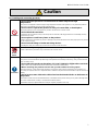
Caution
For installing and connecting products:
Prohibited
● Do not place the product in a location where it will be subjected to high
temperatures.
If the product is subjected to direct sunlight or high temperatures while under operation, it may affect the product’s
performance and reliability and may increase the risk of fire.
● Do not store or operate the product in dusty, oil smoke filled, or humid place.
Placing the product in such environment may increase the risk of fire or electric shock.
● Do not block the vent holes.
If ventilation slots are blocked, it may cause the product to overheat, affecting performance and reliability and may
increase the risk of fire.
● Do not place or stack heavy items on the product.
Failure to observe this precaution may result in damage to the product itself as well as other property and may lead to
the risk of personal injury.
● Do not exceed ratings of outlet and wiring devices.
Exceeding the rating of an outlet may increase the risk of fire and electric shock.
No wet
hands
● Do not handle power plug with wet hands.
Failure to observe this precaution may increase the risk of electric shock.
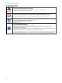
Instruction
● Use and store the product within the specified temperature/humidity range.
If the product is used outside the specified range of temperature and humidity continuously, it may increase the risk
of fire or electric shock.
● Do not place the product at elevations of 1.24 mi. (2,000 m) or higher above sea level.
Failure to do so may shorten the life of the internal parts and result in malfunctions.
● When mounting the product into the rack, provide sufficient cooling space.
Mount the product in a rack meeting EIA standards, and maintain spaces above and below for air circulation. For
your safety as required, attach an L-shaped bracket in addition to the panel mount bracket kit to improve mechanical
stability.
● Never insert screws without the rubber feet into the threaded holes on the bottom of
the product.
Never insert screws alone into the threaded holes on the bottom of the product. Doing so may lead to damage when
the screws contact electric circuitry or components inside the product.
Reinstall the originally supplied rubber feet using the originally supplied screws only.

MSD-62 Series User Guide
8
For operating products:
Hot surfaces
Caution
For products with the hot surfaces caution label only:
● Do not touch the product’s hot surface.
If the product is installed without enough space, it may cause malfunction of other products.
If you touch product’s hot surface, it may cause burns.
Prohibited
● Use only the supplied power cable and AC adapter.
● Do not use the supplied power cable and AC adapter with other products.
If non-compliant adapter or power cables are used, it may increase the risk of fire or electric shock.
Unplug
● If the product won’t be used for an extended period of time, unplug it.
Failure to observe this precaution may increase the risk of fire.
● Unplug the product before cleaning.
To prevent electric shock.
Instruction
● Do not prevent heat release.
If cooling fan stops, power off the product and contact IDK.
Failure to do so may raise internal temperature and increase the risk of malfunction, fire, or electric shock.
● Keep vents clear of dust.
If the vent holes near the cooling fan or near the fan are covered with dust, internal temperatures increase and may
increase the risk of malfunction. Clean the vent holes and near the fan as needed.
If dust accumulates inside of the product, it may increase the risk of fire or electric shock. Periodic internal cleaning,
especially before humid rainy season, is recommended. For internal cleaning, contact your IDK representative.

MSD-62 Series User Guide
9
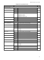
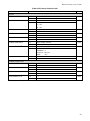
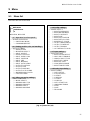
Table of Contents
1 About this Guide ...................................................................................................................................... 13
2 Included items .......................................................................................................................................... 14
3 Product outline ......................................................................................................................................... 15
4 Features ................................................................................................................................................... 16
5 Panels ...................................................................................................................................................... 17
5.1 Front panel .......................................................................................................................................... 17
5.2 Rear panel .......................................................................................................................................... 18
6 System Configuration Example................................................................................................................ 20
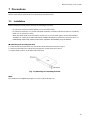
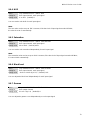
7 Precautions .............................................................................................................................................. 23
7.1 Installation ........................................................................................................................................... 23
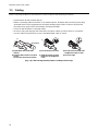
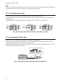
7.2 Cabling ................................................................................................................................................ 24
7.2.1 Cables ......................................................................................................................................... 25
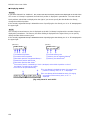
7.2.2 DVI-I input connector .................................................................................................................. 25
7.2.3 Twisted pair cable for extension ................................................................................................. 27
7.2.4 Connecting audio cable ............................................................................................................... 28
7.2.5 Connecting RS-232C cable......................................................................................................... 28
7.2.6 Contact closure ........................................................................................................................... 29
8 Basic Operation ....................................................................................................................................... 30
8.1 Main power switch and standby key ................................................................................................... 30
8.1.1 Power up period .......................................................................................................................... 30
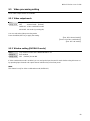
8.2 Selecting input channels ..................................................................................................................... 31
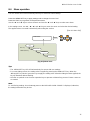
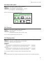
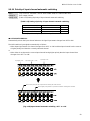
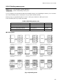
8.3 Video processing mode ...................................................................................................................... 32
8.3.1 Normal mode ............................................................................................................................... 32
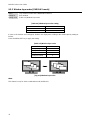
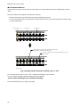
8.3.2 Video combination mode ............................................................................................................. 32
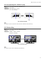
8.3.3 4K mode ...................................................................................................................................... 35
8.4 Menu operation ................................................................................................................................... 37
8.5 Sink device power control ................................................................................................................... 38
8.6 Command control ................................................................................................................................ 38
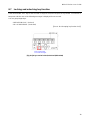
8.7 Locking and unlocking key function .................................................................................................... 39
8.8 Dante output (Optional) ...................................................................................................................... 40
8.8.1 IP network connection ................................................................................................................. 41
8.8.2 Dante Controller .......................................................................................................................... 42
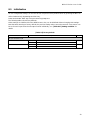
8.9 Initialization ......................................................................................................................................... 43
8.10 Control from WEB browser ................................................................................................................. 56
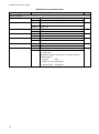
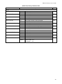
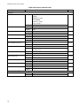
9 Menu ........................................................................................................................................................ 57
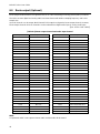
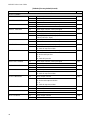
9.1 Menu list .............................................................................................................................................. 57
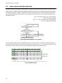
9.2 Input signal automatic detection ......................................................................................................... 60
9.3 Operation from front panel .................................................................................................................. 62
9.3.1 Channel switching mode ............................................................................................................. 62
9.3.2 Control command execution key operation ................................................................................. 62
9.4 Setting position, size, and masking .................................................................................................... 63
9.4.1 Output resolution ......................................................................................................................... 63
9.4.2 Aspect ratio for sink device ......................................................................................................... 64
9.4.3 Aspect ratio ................................................................................................................................. 64
9.4.4 Aspect ratio control ..................................................................................................................... 65
9.4.5 Overscan ..................................................................................................................................... 65
9.4.6 Display position ........................................................................................................................... 65

MSD-62 Series User Guide
10
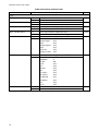
9.4.7 Display size ................................................................................................................................. 66
9.4.8 Masking ....................................................................................................................................... 67
9.4.9 Automatic sizing .......................................................................................................................... 67
9.4.10 Background color ........................................................................................................................ 68
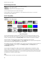
9.4.11 Test pattern ................................................................................................................................. 68
9.5 Video processing setting ..................................................................................................................... 69
9.5.1 Video output mode ...................................................................................................................... 69
9.5.2 Window setting [OVERLAY mode] .............................................................................................. 69
9.5.3 Window layer order [OVERLAY mode] ....................................................................................... 70
9.5.4 Horizontal flip [OFF / OVERLAY mode] ...................................................................................... 71
9.5.5 Window hiding ............................................................................................................................. 71
9.6 Quality setting ..................................................................................................................................... 72
9.6.1 Sharpness ................................................................................................................................... 72
9.6.2 Brightness ................................................................................................................................... 72
9.6.3 Contrast ....................................................................................................................................... 72
9.6.4 HUE ............................................................................................................................................. 73
9.6.5 Saturation .................................................................................................................................... 73
9.6.6 Black level ................................................................................................................................... 73
9.6.7 Gamma ........................................................................................................................................ 73
9.6.8 Default color ................................................................................................................................ 74
9.7 Input settings ....................................................................................................................................... 75
9.7.1 No-signal input monitoring .......................................................................................................... 75
9.7.2 HDCP input setting ...................................................................................................................... 76
9.7.3 Analog input signal parameters .................................................................................................. 77
9.7.4 Automatic detection of video input interruption ........................................................................... 78
9.7.5 Selecting signal of DVI input connector ...................................................................................... 78
9.7.6 HDBaseT input long reach mode ................................................................................................ 78
9.7.7 Fixing settings for each input signal ............................................................................................ 79
9.8 Setting input timing ............................................................................................................................. 80
9.8.1 Automatic measurement ............................................................................................................. 81
9.8.2 The total number of horizontal dots ............................................................................................ 83
9.8.3 Start position ............................................................................................................................... 83
9.8.4 Active area .................................................................................................................................. 84
9.8.5 Automatic measurement of start position .................................................................................... 85
9.8.6 Automatic setting of input timing ................................................................................................. 85
9.8.7 Loading device data .................................................................................................................... 86
9.8.8 Registering device data ............................................................................................................... 86
9.8.9 Tracking ....................................................................................................................................... 86
9.9 Output settings .................................................................................................................................... 87
9.9.1 Output equalizer .......................................................................................................................... 87
9.9.2 Output mode ............................................................................................................................... 87
9.9.3 Synchronous signal output with no input video ........................................................................... 88
9.9.4 Output video with no input video ................................................................................................. 88
9.9.5 Window transition effect .............................................................................................................. 89
9.9.6 Window transition speed ............................................................................................................. 89
9.9.7 Wipe color ................................................................................................................................... 89
9.9.8 Output connector ......................................................................................................................... 90
9.9.9 HDCP output ............................................................................................................................... 90
9.9.10 The number of HDCP retries....................................................................................................... 91
9.9.11 Deep Color .................................................................................................................................. 91

MSD-62 Series User Guide
11
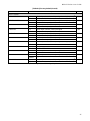
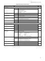
9.9.12 CEC connection .......................................................................................................................... 92
9.9.13 HDCP re-authentication .............................................................................................................. 92
9.9.14 Priority of input channel automatic switching .............................................................................. 93
9.9.15 Ignoring duration after automatic switching ................................................................................ 95
9.9.16 Channel switching mode of automatic switching ........................................................................ 95
9.9.17 HDBaseT output long reach mode .............................................................................................. 95
9.10 Audio setting ....................................................................................................................................... 96
9.10.1 Output level ................................................................................................................................. 97
9.10.2 Output mute ................................................................................................................................ 97
9.10.3 Selecting audio input ................................................................................................................... 97
9.10.4 Audio input level .......................................................................................................................... 97
9.10.5 Lip sync ....................................................................................................................................... 98
9.10.6 Sampling frequency .................................................................................................................... 98
9.10.7 Analog audio output connector ................................................................................................... 99
9.10.8 Multi-channel audio output .......................................................................................................... 99
9.10.9 Test tone ................................................................................................................................... 100
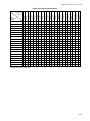
9.11 EDID (Extended Display Identification Data) .................................................................................... 101
9.11.1 EDID .......................................................................................................................................... 101
9.11.2 Resolutions for PCs .................................................................................................................. 102
9.11.3 Input resolution for AV devices ................................................................................................. 104
9.11.4 Deep Color ................................................................................................................................ 105
9.11.5 Audio format .............................................................................................................................. 105
9.11.6 Speaker configuration ............................................................................................................... 106
9.11.7 Copying EDID ........................................................................................................................... 107
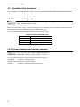
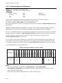
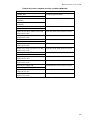
9.12 RS-232C ........................................................................................................................................... 108
9.12.1 RS-232C communication setting .............................................................................................. 108
9.12.2 RS-232C operation mode ......................................................................................................... 108
9.12.3 RS-232C HDBaseT connection ................................................................................................ 109
9.12.4 RS-232C transmitting channel .................................................................................................. 109
9.12.5 RS-232C receiving channel ...................................................................................................... 109
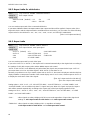
9.13 LAN ................................................................................................................................................... 110
9.13.1 IP address/Subnet mask/Gateway address .............................................................................. 111
9.13.2 LAN operation mode ................................................................................................................. 112
9.13.3 TCP port number ....................................................................................................................... 113
9.13.4 MAC address ............................................................................................................................ 113
9.13.5 Setting HDBaseT LAN .............................................................................................................. 113
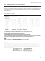
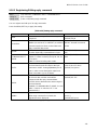
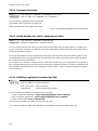
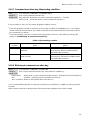
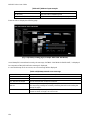
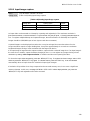
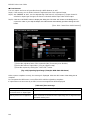
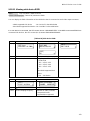
9.14 Setting control command .................................................................................................................. 114
9.14.1 Registering/editing control command ........................................................................................ 116
9.14.2 Registering/Editing reply command .......................................................................................... 121
9.14.3 Command link ........................................................................................................................... 124
9.14.4 Command execution ................................................................................................................. 126
9.14.5 Invalid duration at control command execution......................................................................... 126
9.14.6 Initializing registered command and link ................................................................................... 126
9.14.7 Command execution key: Illuminating condition ....................................................................... 127
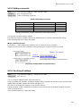
9.14.8 Blinking at command execution key .......................................................................................... 127
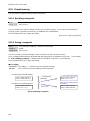
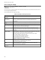
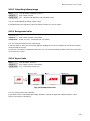
9.15 Preset memory .................................................................................................................................. 128
9.15.1 Recalling crosspoint .................................................................................................................. 128
9.15.2 Saving crosspoint ...................................................................................................................... 128
9.15.3 Editing crosspoint ...................................................................................................................... 129
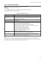
9.15.4 Recalling all settings ................................................................................................................. 129

MSD-62 Series User Guide
12
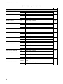
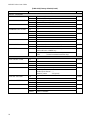
9.15.5 Saving all settings ..................................................................................................................... 130
9.15.6 Copying output setting .............................................................................................................. 131
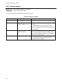
9.15.7 Start-up setting .......................................................................................................................... 132
9.16 Bitmap setting ................................................................................................................................... 133
9.16.1 Sending bitmap file .................................................................................................................... 133
9.16.2 Outputting bitmap image ........................................................................................................... 135
9.16.3 Background color ...................................................................................................................... 135
9.16.4 Aspect ratio ............................................................................................................................... 135
9.16.5 Display position ......................................................................................................................... 136
9.16.6 Assigning input channel ............................................................................................................ 136
9.16.7 Startup bitmap output ................................................................................................................ 136
9.16.8 Dividing memory area ............................................................................................................... 137
9.16.9 Input image capture .................................................................................................................. 139
9.17 Startup setting ................................................................................................................................... 141
9.17.1 Power state ............................................................................................................................... 141
9.17.2 DISPLAY POWER keys ............................................................................................................ 142
9.17.3 Control command execution key ............................................................................................... 143
9.17.4 Key function lock ....................................................................................................................... 144
9.18 Other settings .................................................................................................................................... 145
9.18.1 Grouping key function lock ........................................................................................................ 145
9.18.2 Beep .......................................................................................................................................... 145
9.18.3 Automatic lock of control command execution key ................................................................... 145
9.18.4 Power saving ............................................................................................................................. 146
9.18.5 DISPLAY POWER key pressing duration ................................................................................. 146
9.18.6 HDBaseT input power supply.................................................................................................... 146
9.18.7 Input channel automatic linking ................................................................................................. 147
9.18.8 Top page ................................................................................................................................... 148
9.18.9 Input signal status ..................................................................................................................... 149
9.18.10 Sink device status ..................................................................................................................... 151
9.18.11 Viewing sink device EDID ......................................................................................................... 153
9.18.12 Viewing version information ...................................................................................................... 154
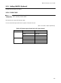
9.19 Setting DANTE (Optional) ................................................................................................................. 155
9.19.1 CH61-CH64 ............................................................................................................................... 155
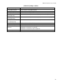
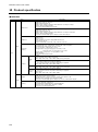
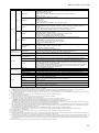
10 Product specification .............................................................................................................................. 156
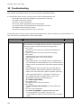
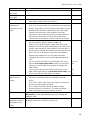
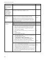
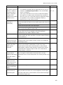
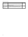
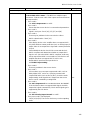
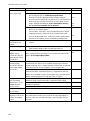
11 Troubleshooting ..................................................................................................................................... 160

MSD-62 Series User Guide
13
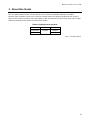
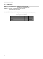
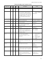
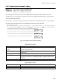
1 About this Guide
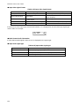
This user guide explains how to use the MSD-62 series switchers (hereafter referred to as “MSD”).
All MSD series switchers include scan conversion and the models are generally divided into two versions,
based on the number of outputs. Since descriptions in this document are for MSD-6204, there may be slight
differences between these models and other MSD models.
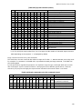
[Table 1.1] MSD-62 series products
Model
Input
Output
MSD-6203
8 inputs
3 outputs
MSD-6204
4 outputs
【See: 5.2 Rear panel】

MSD-62 Series User Guide
14
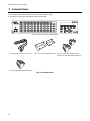
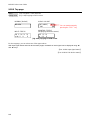
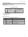
2 Included items
Ensure that all items illustrated below are included in the package.
If any items are missing or damaged, please contact IDK.
One (1) main unit (Figure: MSD-6204)
One (1) power cord, 6 ft. (1.8 m)
Two (2) rack mounting brackets
One (1) 3-position terminal block
Three (3) 5-position terminal blocks
Three (3) 6-position terminal blocks
[Fig. 2.1] Included items

MSD-62 Series User Guide
15
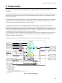
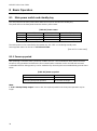
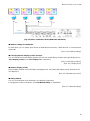
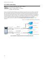
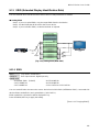
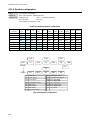
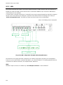
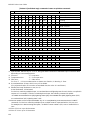
3 Product outline
Models within the MSD-62 series are high performance, digital presentation switchers with built-in scan
converters.
The following input signal formats are supported: HDMI, DVI, composite video, S-video, analog RGB/HV, and
analog YPbPr. All video signal inputs are converted to HDMI signals and output at user definable resolution
formats up to 4K@30.
For audio input and output, digital audio and analog audio formats are supported, and they are cross-routable.
Audio levels of each input and output can be set individually. The lip sync feature provides the user with a
means to control time alignment between the video and audio.
The MSD series switchers may be configured and controlled remotely via RS-232C or TCP/IP (LAN).
Additionally, peripheral devices connected to the MSD can be controlled through RS-232C, LAN, CEC, or
contact closure by registering external device control commands. The waiting function can delay the issuance
of registered commands to peripheral equipment. As an example, a power down command can be delayed
until after sufficient lamp cooling time for a projector has elapsed.
Control commands can be initiated from front panel keys or in response to commands that are issued to the
MSD via RS-232C or LAN. Commands can also be initiated when specified channel selection keys are
operated or the MSD is powered ON.
With Dante (optional), up to 64 audio channels (48 kHz) can be transmitted over one LAN cable.
IN1 to IN7, IN8 (CH1 to CH4)
Scan
converter
Digital video/audio
HDMI DVI
Analog video
Composite
Y/C
RGB
YPbPr
2Inputs
Analog audio
Balanced/Unbalanced LR
Inputs
2
Input EQ
EDID emulator
A/D conversion
A/D conversion
IN1 to IN2
IN7 to IN8
Digital
Analog audio
Balanced/Unbalanced LR
Output
1
MSD-6204
Up to 98 ft. (30 m)*1
Digital video/audio
HDMI DVI Input
1EDID emulator
Input EQ
IN1
Up to 98 ft. (30 m)*1
Digital video/audio/
communication for extension
HDBaseT Inputs
2IN5 to IN6
Digital video/audio
HDMI DVI Inputs
3EDID emulator
Up to 98 ft. (30 m)*1
IN2 to IN4 Input EQ
Digital video/audio
HDMI DVI Outputs
4
Digital video/audio/
communication for extension
HDBaseT Outputs
4
Output EQ Up to 131 ft. (40 m)*2
Analog
Dante*4
LAN
Primary/Secondary
1
chs
4
Video
combination
EDID emulator
PoH
LAN 1Port
D/A conversion
Lip Sync
chs
4
Transmitter
RS-232C1Port
Receiver Video
matrix
switch
Up to 328 ft. (100 m)*3
Up to 328 ft. (100 m)*3
*1 Maximum transmission distances
Up to 98 ft. (30 m) : 1080p@60
Up to 66 ft. (20 m) : 4K@30 (IN1 only)
*2 Maximum transmission distances
Up to 131 ft. (40 m) : 1080p@60
Up to 98 ft. (30 m) : 4K@30
*3 Maximum transmission distances
Up to 328 ft. (100 m) : 4K@30
Up to 492 ft. (150 m) : 1080p (24 bit) in Long reach mode
For long reach mode, video signals up to 1080p (24 bit) can be transmitted to 492 ft. (150 m) at maximum
if using with IDK s HDBaseT products supporting 328 ft. (100 m) transmission.
*4 Dante output is optional.
Dante
(Optional)
chs
64
HUB
CPU
Audio
matrix
switch
IN8 (CH5 to CH8) Output
[Fig. 3.1] MSD-6204 diagram

MSD-62 Series User Guide
16
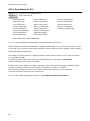
4 Features
■ Video
・ Up to 4K@30
・ Automatic input signal equalization
Input Up to 98 ft. (30 m) : 1080p@60, Up to 66 ft. (20 m) : 4K@30
Output Up to 131 ft. (40 m) : 1080p@60, Up to 98 ft. (30 m) : 4K@30
・ Motion adaptive interlaced/progressive conversion
・ Scan conversion
・ Aspect ratio control
・ Horizontal flip (4K format is not supported)
・ Seamless switching with one black frame
・ Analog/Digital conversion
・ Anti-snow
・ Up to 492 ft. (150 m) over Cat6 cable in Long reach mode*1
■ Audio
・ Embedding/De-embedding
・ Volume adjustment (Input/Output)
・ Lip Sync
・ Dante output (Optional)
■ Video combination (4K format is not supported)
・ Simultaneous display of up to 4 input images on a screen
・ Window display priority setting
・ Window displaying/hiding
■ Control input
・ RS-232C
・ LAN
■ Control output
・ Control command output (e.g. controlling projectors)
・ PJLink
・ CEC (Control sink device power)
・ Contact closure
■ Others
・ PoH (HDBaseT input)
・ EDID emulation
・ All functions and configuration settings accessible through browser
・ Input channel automatic switching
・ Audio breakaway for independent audio and video switching
・ Crosspoint memory
・ Preset memory
・ Last memory
・ Connection Reset
・ Front key function lock
*1 For long reach mode, video signals up to 1080p (24 bit) can be transmitted to 492 ft. (150 m) at maximum
if the MSD is used with IDK’s HDBaseT transmitter or receiver that supports 328 ft. (100 m) extension.

MSD-62 Series User Guide
17
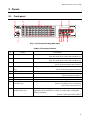
5 Panels
5.1 Front panel
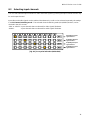
[Fig. 5.1] Front panel drawing (MSD-6204)
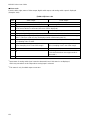
[Table 5.1] Front panel features
#
Feature
Description
①
Standby switch
Standby or powers on the MSD.
【See: 8.1 Main power switch and standby key】
②
Power LED
Shows power status of the MSD.
【See: 8.1 Main power switch and standby key】
③
DISPLAY POWER keys
Power on/off connected sink devices.
【See: 8.5 Sink device power control】
④
Input channel selection
keys
Select input channels.
【See: 8.2 Selecting input channels】
⑤
VFD screen
Displays menus and settings.
⑥
MENU/SET key
Selects menus, edits, controls, and saves settings.
【See: 8.4 Menu operation】
⑦
ESC key
Ends the current menu setting.
⑧
Arrow keys (▲, ▼, ◄, ►)
Navigate menu, move cursor, and change setting values.
⑨
Control command
execution keys
Execute control commands or crosspoint memory.
【See: 9.14 Setting control command】
【See: 9.15 Preset memory】
⑩
Video mode LEDs (4K
MODE/OVER LAY)
Show video processing mode.
Illuminates when 4K MODE or OVERLAY mode (video combination
mode) is selected.
【See: 8.3 Video processing mode】

MSD-62 Series User Guide
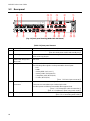
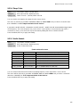
18
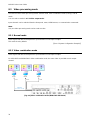
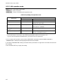
5.2 Rear panel
[Fig. 5.2] Rear panel drawing (MSD-6204 with Dante)
[Table 5.2] Rear panel features
#
Feature
Description
①
Main POWER switch
Controls the main power of the MSD.
【See: 8.1 Main power switch and standby key】
②
HDMI input connectors
Input connectors for HDMI and DVI signals to interface source devices,
such as Blu-ray players.
③
HDMI cable fixing holes
(Not used)
Not used.
④
DVI input connectors
Interfaces with DVI-I or DVI-D cable.
The following video signals can be presented to these inputs:
・DVI
・HDMI
・Analog RGB (such as PC)
・Analog YPbPr (SDTV/HDTV)
・Composite video (NTSC/PAL)
・S-video (NTSC/PAL)
【See: 7.2.2 DVI-I input connector】
⑤
HDBaseT input
connectors
Input connector for HDBaseT signals
Connects to a transmitter over a twisted pair cable.
Provides power to HDBaseT transmitter that supports PoH.
【See: 7.2.3 Twisted pair cable for extension】
【See: 9.7.6 HDBaseT input long reach mode】
⑥
Audio input connectors
Input connectors (5-position terminal block) for analog audio signals
【See: 7.2.4 Connecting audio cable】

MSD-62 Series User Guide
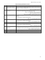
19
[Table 5.3] Rear panel features (Cont’d)
#
Feature
Description
⑦
HDMI output connectors
Output connectors for HDMI and DVI signal, interfaces with sink devices
such as LC monitors and projectors.
【See: 9.9.8 Output connector】
⑧
HDBaseT output
connectors
Output connector for HDBaseT signal
Connects to a remote receiver over a twisted pair cable.
【See: 7.2.3 Twisted pair cable for extension】
【See: 9.9.8 Output connector】
【See: 9.9.17 HDBaseT output long reach mode】
⑨
Audio output connector
Analog audio output connectors interface to amplifiers, speakers, and
mixers.
Connector type is 5-position terminal block.
【See: 7.2.4 Connecting audio cable】
⑩
RS-232C connector
For external control by communication commands
Connector type is 3-position terminal block.
【See: 7.2.5 Connecting RS-232C】
⑪
LAN connector
For external control by communication commands or web browsers
⑫
Contact closures
For external device control by dry contact closure
Connector type is 6-position terminal block.
【See: 7.2.6 Contact closure】
⑬
Dante connectors
(Optional)
Output connector for Dante audio
Input digital and analog audio signals are converted into Dante format.
【See: 8.8 Dante output (Optional)】
⑭
Maintenance port
Factory use only
⑮
Power supply connector
For use with provided power cable.
⑯
Frame ground
Use for bonding chassis to local ground. An M3 screw is used.

MSD-62 Series User Guide
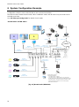
20
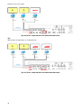
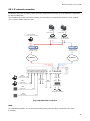
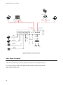
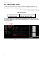
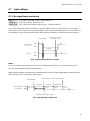
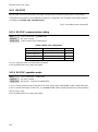
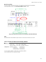
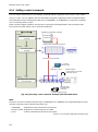
6 System Configuration Example
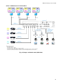
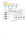
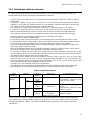
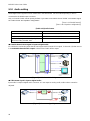
Configuration example: source and sink devices are connected to the MSD.
The MSD has three modes: Normal mode, video combination mode, and 4K mode. Only one mode can be
selected at one time.
See “8.3 Video processing mode” for details of each mode.
<Normal mode: Full HD Video>
HDMI/DVI
Up to 131 ft. (40 m)
Full HD
IP Network
Monitor
Projector
(PJLink)
Analog audio
Speakers
Power amp.
HDMI/DVI
Up to 131 ft. (40 m)
Full HD
Full HD
Mixer
Microphone
Analog audio
Speakers
A
Blu-ray player
HDMI/DVI
Up to 98 ft. (30 m)
Full HD
B
Blu-ray player
HDMI/DVI
Up to 98 ft. (30 m)
Full HD
C
Blu-ray player
HDMI/DVI
Up to 98 ft. (30 m)
Full HD
D
Blu-ray player
HDMI/DVI
Up to 98 ft. (30 m)
Full HD
Power amp.
(Dante supported)
Network audio
HDC-TH100WP
Monitor
B
Full HD
Monitor
A
Full HD
HDMI/DVI
Up to 131 ft. (40 m)
Screen
Category cable
Up to 328 ft. (100 m)*2
Category cable
Up to 328 ft. (100 m)*2
Network audio*1
Laptop
HDMI/DVI
*1 Dante output is optional.
*2 Transmission distances
Up to 328 ft. (100 m) : 4K@30
Up to 492 ft. (150 m) : 1080p (24 bit) in Long reach mode
For long reach mode, video signals up to 1080p (24 bit) can be
transmitted to 492 ft. (150 m) at maximum if the MSD is used
with IDK s HDBaseT transmitter or receiver that supports
328 ft. (100 m) extension.
HDMI/DVI
HDBaseT receiver
[Fig. 6.1] Normal mode (MSD-6204)
Page is loading ...
Page is loading ...
Page is loading ...
Page is loading ...
Page is loading ...
Page is loading ...
Page is loading ...
Page is loading ...
Page is loading ...
Page is loading ...
Page is loading ...
Page is loading ...
Page is loading ...
Page is loading ...
Page is loading ...
Page is loading ...
Page is loading ...
Page is loading ...
Page is loading ...
Page is loading ...
Page is loading ...
Page is loading ...
Page is loading ...
Page is loading ...
Page is loading ...
Page is loading ...
Page is loading ...
Page is loading ...
Page is loading ...
Page is loading ...
Page is loading ...
Page is loading ...
Page is loading ...
Page is loading ...
Page is loading ...
Page is loading ...
Page is loading ...
Page is loading ...
Page is loading ...
Page is loading ...
Page is loading ...
Page is loading ...
Page is loading ...
Page is loading ...
Page is loading ...
Page is loading ...
Page is loading ...
Page is loading ...
Page is loading ...
Page is loading ...
Page is loading ...
Page is loading ...
Page is loading ...
Page is loading ...
Page is loading ...
Page is loading ...
Page is loading ...
Page is loading ...
Page is loading ...
Page is loading ...
Page is loading ...
Page is loading ...
Page is loading ...
Page is loading ...
Page is loading ...
Page is loading ...
Page is loading ...
Page is loading ...
Page is loading ...
Page is loading ...
Page is loading ...
Page is loading ...
Page is loading ...
Page is loading ...
Page is loading ...
Page is loading ...
Page is loading ...
Page is loading ...
Page is loading ...
Page is loading ...
Page is loading ...
Page is loading ...
Page is loading ...
Page is loading ...
Page is loading ...
Page is loading ...
Page is loading ...
Page is loading ...
Page is loading ...
Page is loading ...
Page is loading ...
Page is loading ...
Page is loading ...
Page is loading ...
Page is loading ...
Page is loading ...
Page is loading ...
Page is loading ...
Page is loading ...
Page is loading ...
Page is loading ...
Page is loading ...
Page is loading ...
Page is loading ...
Page is loading ...
Page is loading ...
Page is loading ...
Page is loading ...
Page is loading ...
Page is loading ...
Page is loading ...
Page is loading ...
Page is loading ...
Page is loading ...
Page is loading ...
Page is loading ...
Page is loading ...
Page is loading ...
Page is loading ...
Page is loading ...
Page is loading ...
Page is loading ...
Page is loading ...
Page is loading ...
Page is loading ...
Page is loading ...
Page is loading ...
Page is loading ...
Page is loading ...
Page is loading ...
Page is loading ...
Page is loading ...
Page is loading ...
Page is loading ...
Page is loading ...
Page is loading ...
Page is loading ...
Page is loading ...
Page is loading ...
Page is loading ...
Page is loading ...
Page is loading ...
Page is loading ...
Page is loading ...
Page is loading ...
Page is loading ...
Page is loading ...
Page is loading ...
Page is loading ...
-
 1
1
-
 2
2
-
 3
3
-
 4
4
-
 5
5
-
 6
6
-
 7
7
-
 8
8
-
 9
9
-
 10
10
-
 11
11
-
 12
12
-
 13
13
-
 14
14
-
 15
15
-
 16
16
-
 17
17
-
 18
18
-
 19
19
-
 20
20
-
 21
21
-
 22
22
-
 23
23
-
 24
24
-
 25
25
-
 26
26
-
 27
27
-
 28
28
-
 29
29
-
 30
30
-
 31
31
-
 32
32
-
 33
33
-
 34
34
-
 35
35
-
 36
36
-
 37
37
-
 38
38
-
 39
39
-
 40
40
-
 41
41
-
 42
42
-
 43
43
-
 44
44
-
 45
45
-
 46
46
-
 47
47
-
 48
48
-
 49
49
-
 50
50
-
 51
51
-
 52
52
-
 53
53
-
 54
54
-
 55
55
-
 56
56
-
 57
57
-
 58
58
-
 59
59
-
 60
60
-
 61
61
-
 62
62
-
 63
63
-
 64
64
-
 65
65
-
 66
66
-
 67
67
-
 68
68
-
 69
69
-
 70
70
-
 71
71
-
 72
72
-
 73
73
-
 74
74
-
 75
75
-
 76
76
-
 77
77
-
 78
78
-
 79
79
-
 80
80
-
 81
81
-
 82
82
-
 83
83
-
 84
84
-
 85
85
-
 86
86
-
 87
87
-
 88
88
-
 89
89
-
 90
90
-
 91
91
-
 92
92
-
 93
93
-
 94
94
-
 95
95
-
 96
96
-
 97
97
-
 98
98
-
 99
99
-
 100
100
-
 101
101
-
 102
102
-
 103
103
-
 104
104
-
 105
105
-
 106
106
-
 107
107
-
 108
108
-
 109
109
-
 110
110
-
 111
111
-
 112
112
-
 113
113
-
 114
114
-
 115
115
-
 116
116
-
 117
117
-
 118
118
-
 119
119
-
 120
120
-
 121
121
-
 122
122
-
 123
123
-
 124
124
-
 125
125
-
 126
126
-
 127
127
-
 128
128
-
 129
129
-
 130
130
-
 131
131
-
 132
132
-
 133
133
-
 134
134
-
 135
135
-
 136
136
-
 137
137
-
 138
138
-
 139
139
-
 140
140
-
 141
141
-
 142
142
-
 143
143
-
 144
144
-
 145
145
-
 146
146
-
 147
147
-
 148
148
-
 149
149
-
 150
150
-
 151
151
-
 152
152
-
 153
153
-
 154
154
-
 155
155
-
 156
156
-
 157
157
-
 158
158
-
 159
159
-
 160
160
-
 161
161
-
 162
162
-
 163
163
-
 164
164
-
 165
165
-
 166
166
-
 167
167
-
 168
168
-
 169
169


IDK MSD-6203 Dan User guide
- Type
- User guide
- This manual is also suitable for
Ask a question and I''ll find the answer in the document
Finding information in a document is now easier with AI
Related papers
Other documents
-
Shelly 3 Circuit WiFi Smart Relay Pro 3 User guide
-
DVDO AIR User manual
-
 C4i HDMX02 User manual
-
-
 VIV SIXFIVE VIV68DSP Instructions Manual
-
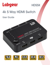 Labgear HDS5K User guide
-
infobit iSwitch 401 User manual
-
 FERRISA HDSW0040M1 User manual
-
-
Orei HDS-401MV User manual


