Page is loading ...

Digital Multi Switcher with Integrated Audio Power Amplifier
MSD-701AMP
<Command Reference Guide>
Ver.1.5.0
⚫ Thank you for choosing our product.
⚫ To ensure the best performance of this product, please read this user guide fully and carefully before
using it and keep this manual together with the product for future reference as needed.
IDK Corporation

MSD-701AMP Command Guide
2
Trademarks
⚫ HDBaseT™ and the HDBaseT Alliance Logo are trademarks of the HDBaseT Alliance.
⚫ The terms HDMI and HDMI High-Definition Multimedia Interface, and the HDMI Logo are trademarks or
registered trademarks of HDMI Licensing Administrator, Inc. in the United States and other countries.
⚫ PJLink is a trademark in Japan, the United States, and other countries/regions.
⚫ All other company and product names mentioned in this manual are either registered trademarks or
trademarks of their respective owners. In this manual, the “®” or “™” marks may not be specified.

MSD-701AMP Command Guide
3
Before reading this manual
⚫ All rights reserved.
⚫ Some information contained in this Command guide such as exact product appearance, communication
commands, and so on may differ depending on the product version.
⚫ This Command guide is subject to change without notice. You can download the latest version from IDK’s
website at: www.idkav.com
The reference manual consists of the following two volumes:
■ User guide: Please download the User guide from the website above.
Provides explanations and procedures for operations, installation, connections among devices,
I/O adjustment and settings.
■ Command guide (this document):
Provides explanations and procedures for external control using RS-232C and LAN communications.

MSD-701AMP Command Guide
4
Table of Contents
1 About this Guide ........................................................................................................................................ 5
2 Communication configuration and Specifications ...................................................................................... 5
2.1 RS-232C communication ...................................................................................................................... 5
2.1.1 RS-232C connector specification .................................................................................................. 5
2.1.2 RS-232C communication specification ......................................................................................... 5
2.1.3 Setting up RS-232C communication ............................................................................................. 6
2.2 LAN communication .............................................................................................................................. 7
2.2.1 LAN connector specification.......................................................................................................... 7
2.2.2 LAN communication specification ................................................................................................. 7
2.2.3 Setting up LAN communication ..................................................................................................... 8
2.2.4 The number of TCP-IP connections .............................................................................................. 9
3 Command ................................................................................................................................................. 10
3.1 Summary ............................................................................................................................................. 10
3.2 Command list ...................................................................................................................................... 11
3.3 Details of commands .......................................................................................................................... 17
3.3.1 Error status .................................................................................................................................. 17
3.3.2 Standby ....................................................................................................................................... 18
3.3.3 Channel switching mode ............................................................................................................. 19
3.3.4 Output position, size, and masking ............................................................................................. 22
3.3.5 Output .......................................................................................................................................... 30
3.3.6 Input position, size, and masking ................................................................................................ 39
3.3.7 Input ............................................................................................................................................ 45
3.3.8 Input timing .................................................................................................................................. 51
3.3.9 Input channel automatic switching .............................................................................................. 60
3.3.10 Picture controls ........................................................................................................................... 63
3.3.11 Output audio ................................................................................................................................ 69
3.3.12 Input audio .................................................................................................................................. 77
3.3.13 EDID ............................................................................................................................................ 86
3.3.14 RS-232C ...................................................................................................................................... 93
3.3.15 LAN ............................................................................................................................................. 95
3.3.16 Control commands ...................................................................................................................... 99
3.3.17 Preset memory .......................................................................................................................... 112
3.3.18 Bitmap ....................................................................................................................................... 120
3.3.19 Configuring MSD ....................................................................................................................... 128
3.3.20 Status ........................................................................................................................................ 130

MSD-701AMP Command Guide
5
1 About this Guide
This guide contains the procedure for controlling the MSD-701AMP (hereafter referred to as “MSD”) using
commands via RS-232C communication or LAN communication.
2 Communication configuration and Specifications
2.1 RS-232C communication
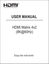
2.1.1 RS-232C connector specification
Insert and secure the wires from the RS-232C cable into the supplied 3-pin captive screw connector, and then
insert the captive screw connector into the mating connector on the MSD.
28 AWG to 16 AWG conductor gauge is recommended. The recommended wire strip length is 0.28 in. (7 mm).
Short RTS/CTS and DTR/DSR as needed.
Tx
Rx
GND
Up to 0.28" (7mm)
Control device
Tx
Rx
GND
MSD
RxD
TxD
GND
Signal name
(Receive Data)
(Transmit Data)
(Ground)
[Fig. 2.1] RS-232C connector
2.1.2 RS-232C communication specification
[Table 2.1] RS-232C specification
Compliant standard
RS-232C
Baud rate
4800/9600/19200/38400/57600/115200 [bps]
Data bit length
7/8 [bit]
Parity check
NONE, EVEN, ODD
Stop bit
1/2 [bit]
X parameter
Invalid
Flow control
None
Delimiter
CR LF (Carriage return and line feed, 0D and 0A in hex)
Communication method
Full duplex

MSD-701AMP Command Guide
6
2.1.3 Setting up RS-232C communication
(1) Connect the MSD and the control device via an RS-232C cable.
(2) Set the RS-232C communication as follows:
・ RS-232C communication : Baud rate, data bit length, parity check, and stop bit
・ Operation mode of RS-232C communication : RECEIVER mode
【Reference: User Guide】
(3) For the control device, set the same values in the same way as RS-232C communication (baud rate, data
bit length, parity check, and stop bit) in step (2) above.
(4) Send a communication command from the control device to the MSD in order to check the control status of
the MSD.
Step (2)
Step (1)
RS-232C cable
Step (4)
Communication
command
Step (3)
Laptop
[Fig. 2.2] Setting RS-232C communication
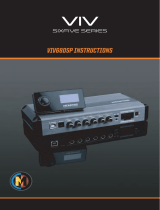
■ Operation example of RS-232C communication
Projector
Category cable RS-232C cable
Outputs control command to external device
Laptop RS-232C cable
Power amp.
Communication
command to MSD
Outputs control
command to external
device
HDBaseT receiver
[Fig. 2.3] Example of RS-232C communication

MSD-701AMP Command Guide
7
2.2 LAN communication
2.2.1 LAN connector specification
Pin assignment of the LAN connector is as follows.
Since Auto MDI/MDI-X that distinguishes and switches straight/cross cables automatically is supported, extra
care is not necessary to connect the MSD to PC, HUB or the like.
Light in green while link is established.
Blinks in green while data is being
sent/received.
Light in amber if the send/receive
rate is 100 Mbps.
Goes off if it is 10 Mbps.
81
LAN connector
8-pin RJ-45 connector
(Rear panel)
RX+
N.C.
TX+
Pin#
1
3
2
4
6
5
7
8
Signal Name
TX-
N.C.
RX-
N.C.
N.C.
(Transmitted Data +)
(Transmitted Data -)
(Received Data +)
(Not Connected)*
(Received Data -)
(Not Connected)*
(Not Connected)*
(Not Connected)*
MDI
TX+
N.C.
RX+
RX-
N.C.
TX-
N.C.
N.C.
(Received Data +)
(Received Data -)
(Transmitted Data +)
(Not Connected)*
(Transmitted Data -)
(Not Connected)*
(Not Connected)*
(Not Connected)*
MDI-X
*Not used
[Fig. 2.4] LAN connector
2.2.2 LAN communication specification
[Table 2.2] Specification of LAN communication
Physical layer
10Base-T (IEEE802.3i)/100Base-TX (IEEE802.3u)
Network layer
ARP, IP, ICMP
Transport layer
TCP
Port used for command control : 23, 1100, 6000 to 6999
Port used for WEB browser control(HTTP) : 80, 5000 to 5999
Note:
Up to 8 connections can be used simultaneously.

MSD-701AMP Command Guide
8
2.2.3 Setting up LAN communication
(1) Connect the MSD and the control device via a LAN cable.
(2) Set up LAN communication as follows:
・ Set IP address and subnet mask
・ Operation mode of LAN communication : RECEIVER mode
・ TCP pot number : 23, 1100, 6000 to 6999
【Reference: User guide】
(3) Establish the connection from the control device to the IP address and TCP port that are set to the MSD in
step (2) above.
(4) Send a communication command from the control device to the MSD in order to check the control status of
the MSD.
Step (3)
Laptop Step (2)
Step (1)
LAN cable
Step (4)
Communication
command
[Fig. 2.5] Setting LAN communication
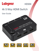
■ Operation example of LAN communication
Projector
Category cable LAN cable
Outputs control command to external device
Laptop LAN cable
Power amp.
Communication
command to MSD
Outputs control
command to external
device
HDBaseT receiver
Switching hub
Control input
Connections
1 2 3 4 5 6 7 8
Bidirectional communication
[Fig. 2.6] Example of LAN communication

MSD-701AMP Command Guide
9
2.2.4 The number of TCP-IP connections
The MSD supports up to eight simultaneous TCP-IP connections (eight logical ports).
To maintain optimal system accessibility, it is advisable to issue “port-open” and “port-close” commands
before and after command or query strings are issued. This approach enables eight or more control devices
to be effectively interfaced simultaneously and without concern for communication errors.
[Table 2.3] Increasing connections
Your PC software
MSD
Connecting TCP-IP
→
(Occupying 1 port)
Sending command (@xxx)
→
←
Replying command (@xxx)
Closing TCP-IP
→
(Releasing 1port)
Note:
As a safeguard, the MSD incorporates a 30-second timeout window for each port. If any port is inactive for
more than 30 seconds, it will be closed automatically.

MSD-701AMP Command Guide
10
3 Command
3.1 Summary
A command consists of “@” (“40” in hexadecimal), 3 one-byte alphabetical characters (upper and lower
cases), and parameters (one-byte numbers). For some commands, multiple parameter values can be
specified or parameters are not necessary.
“,”( a comma, “2C” in hex) is indicated between a command and parameter and between two parameters.
“ ” is indicated as a delimiter CR LF (return+line feed, “0D” and “0A” in hex).
Processing is executed by sending a delimiter at the end of the command.
Example: @SPM,2
■ If there is an error:
An error command is returned if an undefined command or wrong parameter is included.
Example: @ABC,1
@ERR,1
■ Using as HELP
If only delimiter is sent, command list as the help command is returned.

MSD-701AMP Command Guide
11
3.2 Command list
■ Error status
Command
Function
Page
@ERR
Error status
17
■ Standby
Command
Function
Page
@GDS / @SDS
Standby
18
■ Channel switching mode
Command
Function
Page
@GSW / @SSW
Switching video and audio channel simultaneously
19
@GSV / @SSV
Switching video channel
20
@GSA / @SSA
Switching audio channel
20
@GPI / @SPI
PinP layout pattern
21
■ Output position, size, and masking
Command
Function
Page
@GOT / @SOT
Output resolution
22
@GTD
Actual output resolution
23
@GUM / @SUM
Aspect ratio for windows
24
@GOP / @SOP
Image position
25
@GOS / @SOS
Image size
26
@GOM / @SOM
Cropping
27
@GBC / @SBC
Background color
28
@GTP / @STP
Test pattern
29
@OAS
Image Initialization
29
■ Output
Command
Function
Page
@GVO / @SVO
Output signal
30
@GBO / @SBO
Output video with no input video
31
@GEN / @SEN
HDCP output
32
@GHR / @SHR
HDCP retries
33
@HAU
HDCP re-encryption
33
@GEQ / @SEQ
Output equalizer
34
@GDM / @SDM
Output format
34
@GOA / @SOA
HDBaseT output long reach mode
35
@GDC / @SDC
Deep Color output
35
@GFF / @SFF
Window transition effect
36
@GFT / @SFT
Window transition speed
37
@GWC / @SWC
Wipe color
37
@GCE / @SCE
CEC connection
38

MSD-701AMP Command Guide
12
■ Input position, size, and masking
Command
Function
Page
@GAP / @SAP
Aspect ratio
39
@GAR / @SAR
Aspect ratio control
39
@GOV / @SOV
Overscan
40
@GNP / @SNP
Image position
41
@GNS / @SNS
Image size
42
@GNM / @SNM
Cropping
43
@IAS
Image initialization
44
■ Input
Command
Function
Page
@GIE / @SIE
Input connector
45
@GIN / @SIN
DVI input connector signal
45
@GDT / @SDT
No-signal input monitoring
46
@GHE / @SHE
HDCP input
46
@GIQ / @SIQ
Input equalizer
47
@GIA / @SIA
HDBaseT input long reach mode
47
@GHP / @SHP
HDBaseT power supply
48
@GAI / @SAI
Analog input signal parameters
48
@GID / @SID
Automatic detection of video input interruption
49
@GFX / @SFX
Fixing settings for each input signal
50
■ Input timing
Command
Function
Page
@AIS / @AIT
Automatic measurement
51
@GHT / @SHT
The total number of horizontal pixels
52
@GHS / @SHS
Horizontal start position
53
@GHD / @SHD
Horizontal active area
54
@GVS / @SVS
Vertical start position
55
@GVD / @SVD
Vertical active area
55
@GIS / @SIS
Automatic measurement of start position
56
@GSM / @SSM
Automatic setting of input timing
56
@RTT
Initializing/Recalling input timing
57
@STT
Saving analog input timing
58
@GTK / @STK
Tracking
59

MSD-701AMP Command Guide
13
■ Input channel automatic switching
Command
Function
Page
@GAU / @SAU
Signal ON priority
60
@GOF / @SOF
Signal OFF priority
61
@GMT / @SMT
Ignoring duration after automatic switching
62
@GAD / @SAD
Channel switching mode of automatic switching
62
■ Picture controls
Command
Function
Page
@GOB / @SOB
Output brightness
63
@GOC / @SOC
Output contrast
64
@GGM / @SGM
Output gamma
64
@ODC
Output video correction initialization
65
@GFL / @SFL
Input sharpness
65
@GIB / @SIB
Input brightness
66
@GIC / @SIC
Input contrast
66
@GHU / @SHU
Input hue
67
@GST / @SST
Input saturation
67
@GSU / @SSU
Input black level
68
@IDC
Input video correction initialization
68
■ Output audio
Command
Function
Page
@GUC / @SUC
Audio output
69
@GAV / @SAV
Audio output level
70
@SOL
Adjusting audio output level
71
@GOL
Audio output limit status
71
@GTR / @STR
Tone control
72
@GAM / @SAM
Mute
72
@GLO / @SLO
Output Lip Sync
73
@GSF / @SSF
Sampling frequency
73
@GFD
Actual sampling frequency
74
@GMI / @SMI
Audio mixing
74
@GMD / @SMD
Multi-channel audio output
75
@GCH / @SCH
Multi-channel audio output priority
75
@GPO / @SPO
SPEAKER 2 output connector
76
@GAT / @SAT
Test tone
76

MSD-701AMP Command Guide
14
■ Input audio
Command
Function
Page
@GAS / @SAS
Audio input
77
@GIO / @SIO
Audio input level offset (For each audio input connector)
78
@GSO / @SSO
Audio input level offset (For each video input channel)
78
@SDZ
Adjusting audio input level
79
@GDZ
Audio input limit status
79
@GLR / @SLR
LINE input reference level
80
@GMR / @SMR
MIC input reference level
80
@GCS / @SCS
Compressor
81
@GAQ / @SAQ
Equalizer
82
@GHW / @SHW
Automatic feedback suppressor (Setting control level)
83
@GHO
Automatic feedback suppressor (Getting frequency that is being
controlled)
84
@GLY / @SLY
Input Lip Sync
85
@GAW / @SAW
Stable audio input wait
85
■ EDID
Command
Function
Page
@GED / @SED
EDID selection
86
@GVF / @SVF
Resolution
87
@RME
Copying EDID
88
@GHL / @SHL
HDMI/DVI
88
@GHZ / @SHZ
Frame rate
89
@GDI / @SDI
Deep Color
89
@GAF / @SAF
Audio format
90
@GSP / @SSP
Speaker configuration
91
■ RS-232C
Command
Function
Page
@GCT / @SCT
RS-232C communication
93
@GCF / @SCF
RS-232C operation mode
94
■ LAN
Command
Function
Page
@GIP / @SIP
IP address
95
@GSB / @SSB
Subnet mask
95
@GGW / @SGW
Gateway address
96
@GMC
MAC address
96
@GLP / @SLP
TCP port number
97
@GLF / @SLF
LAN operation mode
98

MSD-701AMP Command Guide
15
■ Control commands
Command
Function
Page
@GEC / @SEC
Registering/Editing control command (Communication command)
99
@GEC / @SEC
Registering/Editing control command (Displaying received data)
101
@GEC / @SEC
Registering/Editing control command (Contact closure)
103
@GEC / @SEC
Registering/Editing control command (CEC)
104
@GRC / @SRC
Registering/Editing reply command
105
@GCC / @SCC
Command link
106
@GTG / @STG
Toggle operation
107
@GUP / @SUP
Plane to be executed when powered ON
107
@EXC
Command execution
108
@GSK / @SSK
DISPLAY POWER button
108
@DEC
Initializing registered command and link
109
@GIT / @SIT
Invalid duration at control command execution
109
@GTL / @STL
COMMAND button illuminating condition
110
@GTF / @STF
Blinking at command button
111
■ Preset memory
Command
Function
Page
@RCM
Recalling crosspoint
112
@RCV
Recalling crosspoint (Setting video channel)
112
@RCA
Recalling crosspoint (Setting audio channel)
112
@SCM / @SEM
Saving crosspoint
113
@SCV / @SEV
Saving crosspoint (Setting video channel)
114
@SCA / @SEA
Saving crosspoint (Setting audio channel)
115
@GCM / @ECM
Editing crosspoint
116
@GCV / @ECV
Editing crosspoint (Setting video channel)
117
@GCA / @ECA
Editing crosspoint (Setting audio channel)
118
@RPM
Recalling all settings
118
@SPM
Saving all settings
119
@GMU / @SMU
Start-up setting
119
■ Bitmap
Command
Function
Page
@GBM / @SBM
Bitmap image output
120
@GBB / @SBB
Background color
121
@GBT / @SBT
Aspect ratio
122
@GZP / @SZP
Image position
123
@GBA / @SBA
Assigning input channel
124
@GPB / @SPB
Start-up bitmap output
125
@GBD / @SBD
Dividing memory area
126
@GBV
Memory area status
126
@GFZ / @SFZ
Freeze
127
@CAP
Input image capture
127

MSD-701AMP Command Guide
16
■ Configuring MSD
Command
Function
Page
@GLS / @SLS
Front panel security lockout
128
@GLM / @SLM
Grouping front panel security lockout
128
@GBZ / @SBZ
Beep
129
■ Status
Command
Function
Page
@GSS
Input signal and sink device status
130
@GES
Viewing sink device EDID
134
@GHC
System status
135
@GIV
Device information
135

MSD-701AMP Command Guide
17
3.3 Details of commands
In this section, “MAIN” and “PinP” stand for main window and PinP window respectively that are displayed on
the sink device.
3.3.1 Error status
@ERR
Error status
Description
Response in case the command is not executed
Response
@ERR, error
Parameter
error: Error status
1 = Erroneous parameter format or value
2 = Undefined command or wrong format
3 = Currently cannot be used
4 = Not used.
5 = The command could not be executed, because the control command was
not registered.
6 = The command could not be processed since another command was being
executed.
7 = Automatic measurement of input timing failed.
8 = Loading EDID from the sink device failed.
9 = Not used.
10 = The control command was stopped according to the stop condition.
11 = The control command was stopped since the number of retries exceeded
the set value of “RETRY”.
12 = The control command of PJLink was stopped since the password did not
match.
13 = The image could not be captured since the image size to be captured
exceeded the reserved memory size.
14 = Capturing input image failed.
Getting
example
Command
Response
@IOS
@ERR,2
Description
@IOS is sent.
Command format error
Remarks
-

MSD-701AMP Command Guide
18
3.3.2 Standby
@GDS / @SDS
Standby
Getting
Command
@GDS
Response
@GDS, onoff
Setting
Command
@SDS, onoff
Response
@SDS, onoff
Parameter
onoff: Standby
0 = OFF (Standby), 1 = ON (Power on)
Getting
example
Command
Response
@GDS
@GDS,1
Description
Getting the standby status
The MSD is powered on.
Setting
example
Command
Response
@SDS,1
@SDS,1
Description
Powering on the MSD
Completed
Remarks
-

MSD-701AMP Command Guide
19
3.3.3 Channel switching mode
@GSW / @SSW
Switching video and audio channel simultaneously
Getting
Command
@GSW
Response
@GSW, main_video, main_audio, pinp_video, pinp_audio
Setting
Command
@SSW, input, window
Response
@SSW, input, window
Parameter
main_video : Video input channel of main window
pinp_video : Video input channel of PinP window
main_audio : Audio input channel of main window
pinp_audio : Audio input channel of PinP window (“0” fixed)
input : Video and audio input channel
0 (OFF) [Default], 1 to 7 = IN1 to 7
window: Window
0 = All windows, 1 = MAIN, 2 = PinP
Getting
example
Command
Response
@GSW
@GSW,2,2,1,0
Description
Getting the input channel
Main window : IN2 (Video and audio)
PinP window : IN1
Setting
example
Command
Response
@SSW,1,0
@SSW,1,0
Description
Selecting the input channel of all windows to IN1
Completed
Remarks
-

MSD-701AMP Command Guide
20
@GSV / @SSV
Switching video channel
Getting
Command
@GSV
Response
@GSV, main_video, pinp_video
Setting
Command
@SSV, input, window
Response
@SSV, input, window
Parameter
main_video : Video input channel of main window
pinp_video : Video input channel of PinP window
input : Video input channel
0 = OFF [Default], 1 to 7 = IN1 to 7
window: Window
0 = All windows, 1 = MAIN, 2 = PinP
Getting
example
Command
Response
@GSV
@GSV,1,0
Description
Getting the video input channel
Main window : IN1
PinP window : OFF
Setting
example
Command
Response
@SSV,1,0
@SSV,1,0
Description
Setting the video input channel of main window and PinP window to IN1
Completed
Remarks
-
@GSA / @SSA
Switching audio channel
Getting
Command
@GSA
Response
@GSA, input
Setting
Command
@SSA, input, window
Response
@SSA, input, window
Parameter
input: Audio input channel
0 = OFF [Default], 1 to 7 = IN1 to 7
window: Window
“1” fixed
Getting
example
Command
Response
@GSA
@GSA,1
Description
Getting the audio input channel
Main window: IN1
Setting
example
Command
Response
@SSA,1,1
@SSA,1,1
Description
Selecting the input channel of main window to IN1
Completed
Remarks
-
/