Page is loading ...

1
Emco Enterprises, Inc., is a wholly owned subsidiary of Andersen Corporation. Emco Enterprises, Inc.
manufactures and supports the limited warranties for Andersen
®
and EMCO
®
doors. “Andersen”,
“EMCO” and all other marks where denoted are trademarks of Andersen Corporation. ©2018
Andersen Corporation. All rights reserved.
Installation Guide
Please Do Not Return Product to Store!
with any questions regarding installation, lost part replacement, or anything else related to your retractable
insect screen purchase. Replacement parts can also be found at: parts.andersenstormdoors.com
Read this entire guide before you begin your installation. If your abilities do not
match the requirements of this installation, contact an experienced contractor.
PLEASE call the Storm Door Solution Center at 844-813-6664,
For installation help please visit www.AndersenLuminAire.com/install
Designed for 32” – 36” wide by 80” tall single hinged doors with suitable mounting surface.
PARTS OVERVIEW
2
4
5
1
1 2
5
3
3
4
4
6
7
6
4
4
6
3
8
7
Your installation kit should contain the following parts.
Andersen SDD, PO Box 853
Des Moines, IA 50306-0853
Rev 06-2018v1 Print in Color
p/n 900106
for Andersen® LuminAire
™
Retractable Insect Screen Door
with SlideAway® Insect Screen System
Screen Housing (one with handle & orange clips)
Latch Housing (one without handle or clips)
Screen Tracks (top and bottom)
End Caps (attached to ends of housings)
Sill Adapter
Orange Installation Clips
Shipping Plastic Wrap
Not Shown
Screw Pack containing:
• 1 inch #8 screws (qty 6)
• ½ inch #8 self-tapping screws (qty 3)
• ⁄ inch Drill Bit
• #2 Phillips Bit
NOTE:
The orange installation clips attached to the Screen
Housing provide product protection during shipping and
installation. DO NOT extend screen from housing or remove
installation clips until instructed.
To avoid product damage, be sure to place all parts of your retractable
insect screen on a soft non-abrasive surface such as carpet, drop cloth
placed on your lawn or cardboard.
NOTICE

2
To install the retractable insect screen door, you must verify that the opening width,
height and mounting surface are suitable size to properly install into the opening.
1. Measure the width at the top (W1), middle (W2), and bottom (W3) of the opening (see Figure 1).
Measure from the inside of the exterior trim. Utilizing the narrowest width, reference chart below.
2. Measure the height at the center of the opening, from the bottom of the exterior trim at the top
of opening down to the sill at the bottom of opening. Reference chart for height compliance.
Configuration Widths
(Adjustable Width - Use for Step 1b)
Opening Widths
(Configuration Ranges)
Opening Heights
36 Configuration 34" – 36 ⁄"
80" (80" – 80 ⁄")
32 Configuration 31 ⁄" – 33 ⁄" Also Available in
See Appendix A
(Pg. 6) Less than 31 ⁄"
78" (78"–78 ⁄") or 84" (84"– 84 ⁄")
3. Make sure that the exterior trim meets the mounting surface requirements to accommodate
the retractable insect screen assembly (see Figure 2). The assembly needs 3/4" at surface on
exterior trim face and 3/4" minimum depth of mounting surface.
MEASURE - VERIFY MOUNTING SURFACE REQUIREMENTS AND MEASURE DOOR OPENING
*
Figure 1
W3
H
W2
W1
Figure 2
3/4" MIN
DEPTH
3/4" MIN FLAT
SURFACE ON FACE
Verify that the exterior brickmould, trim board or casing (exterior trim) is rmly attached to the
opening structure and is a material that is suitable to suciently fasten the retractable insect
screen to the door opening. The performance of the retractable insect screen could be eected
over time if it is not suciently fastened to the opening.
* Andersen retractable insect screens are designed to be installed on the exterior of the home. However, the door can be installed on the interior
(i.e. for outswing door openings) as long as the opening meets the sizing and mounting surface requirements. For changing handle orientation, see page 7.
SAFETY FIRST: Please read and follow all Cautions and Warnings in this guide.
RECOMMENDED TOOLS
Drill
Safety Glasses
Sealant
#2 Phillips Bit
(provided)
1/8 Drill Bit
(provided)
!
!
1/2”
1/2”
1/2”
1”
1 1/2”
2”
1 1/2”
5/8”
5/8”
Work Gloves
The retractable insect screen is intended for reasonable
insect control and not the retention of objects, persons,
or pets within the interior. The retractable insect screen
will not stop a person from falling through the door.
Follow manufacturers' instructions for hand and power
tools. Always wear safety glasses. Failure to do so could
result in injury, product or property damage.
Windows and doors can be heavy. Use safe lifting techniques and a reasonable number of people with enough
strength to lift, carry, and install window and door products. Heavier windows and doors will require mechanical
assistance. Failure to do so could result in injury, product or property damage.
Metal fasteners and components could corrode when exposed to preservative-treated or re-retardent treated
lumber. Use approved fasteners and components to fasten window or door. Failure to do so could cause a failure
resulting in injury, product or property damage.
Fastener must attach to a structural framing member with a 1" minimum fastener embedment. Failure to do so
could result in injury, product or property damage.
DO NOT remove screws that attached installation clips or gusset plates to window or door frames. Doing so could
result in injury, product or property damage.
Metal components of the retractable insect screen may
become hot when exposed to sunlight.
IMPORTANT
WARNING
WARNING
WARNINGCAUTION
Major Injury / Death
Product or Property
Damage
Minor Injury
Procedure and Product
Information
This is the Safety Alert Symbol used to alert you to
potential injury hazards. Obey all safety messages that
follow this symbol to avoid possilbe injury or death.
WARNING
NOTICE
CAUTION
IMPORTANT
Signal Word and Consequence
COULD
Result in:
COULD
Result in:
COULD
Result in:
Tape Measure
Screwdriver
!
!
1/2”
1/2”
1/2”
1”
1 1/2”
2”
1 1/2”
5/8”
5/8”
Hacksaw
!
!
1/2”
1/2”
1/2”
1”
1 1/2”
2”
1 1/2”
5/8”
5/8”
Metal
File
For installs less
than 31-⁄" wide
Figure 3a
Figure 3b
No Modication Required
See Appendix B
MOUNTING
SURFACE
MOUNTING
SURFACE
DOOR
SILL
DOOR
SILL
!
!
1/2”
1/2”
1/2”
1”
1 1/2”
2”
1 1/2”
5/8”
5/8”
Scissors
If the Door Sill doesn’t extend past the Mounting Surface or doesn’t
have sucient support, product damage, injury or both may occur.
•
If the Door Sill extends past your exterior trim Mounting Surface
and is supported, no modication is required (see Figure 3a).
•
If the Door Sill is extended without support or not extended (see Figure 3b),
you will need to add support blocking. See Appendix B (on page 6).
CAUTION

3
A
36
32
A
ASSEMBLE
SCREEN
TRACKS &
HOUSINGS
1
A
a1 Unpack the housings and screen tracks onto a non-abrasive surface, with the side labeled Interior facing up. Leaving the screen in the retracted position,
arrange the components so the letters marked on the Screen Tracks and the letters marked on the Endcaps align (A to A, B to B, C to C and D to D).
a2 Conrm the Fastener Clips on endcaps A and C are in the open position. Starting at corner A, slide the Receiving Tab on Endcap A inside the Screen Track.
Ensure the Receiving Tab ts inside the Screen Track, and the Screen Track slides into the Channel. (see “correct” above).
(Visit AndersenLuminAire.com/Install to view a video of this step.)
a3 Repeat for corner C, then continue to corners B and D. They do not have Fastener Clips, which allows the door assembly to adjust to your door opening width.
a4 Use the “36 Conguration” for openings 34 - 36 ⁄" wide or “32 Conguration” for openings less than 34" wide in step b.
(If the opening is narrower than 31 ⁄" wide, See Appendix A on page 6.)
b1 If the opening is between 34" and 36 ⁄", adjust Screen Track A
until 36" line aligns with edge of Endcap A.
b2 Rotate the Fastener Clip up until it snaps into the closed position.
b3 Repeat steps for side C.
b1 If the opening is less than 34", adjust Screen Track A until 32" line
aligns with edge of Endcap A.
b2 Rotate the Fastener Clip up until it snaps into the closed position.
b3 Repeat steps for side C.
A
A
A
36
32
RECEIVING TAB
SLIDES INSIDE SCREEN TRACK TUBING!
A
A
A
32
36 Configuration
(use for opening widths between 34" to 36
-
⁄")
32 Configuration
(use for opening widths less than 34")
A
A
A
36
32
FASTENER CLIP
IN OPEN POSITION
INTERIOR
LABEL
INTERIOR
LABEL
SCREEN
TRACK A
SCREEN
TRACK A
CHANNEL
FOR SCREEN TRACK
CHANNEL
FOR SCREEN TRACK
ENDCAP A
ENDCAP A ENDCAP A
A
C
B
D
A
C
B
D
FASTENER CLIP FASTENER CLIP
36" LINE 32" LINE
SCREEN TRACK A SCREEN TRACK A
b
Screen Housing Latch Housing Screen Track (A/B) Screen Track (C/D)
KEY REFERENCES
D
A
A
A
36
32
CORRECT
INCORRECT
RECEIVING TAB
FITS INSIDE SCREEN TRACK
RECEIVING TAB
FITS INSIDE SCREEN TRACK
RECEIVING TAB SHOULD NOT
BE OUTSIDE SCREEN TRACK
Visit AndersenLuminAire.com/install
to view a video of this step.
Screw Flanges
Receiving Tabs
Letter Labels
Fastener Clips
OR
1
2
11
3
4
4
3 3
3
3
22
ALL ITEMS DURING THE ASSEMBLY STEPS
SHOULD BE LAYING FLAT ON THE GROUND
a
Receiving Tabs on the Endcaps must
slide inside the Screen Track. Product
damage may occur if Receiving Tab is
forced outside the screen track.
NOTICE

4
PLACE AND
FASTEN
ASSEMBLY
INTO OPENING
2
1/8"
!
!
1/2”
1/2”
1/2”
1”
1 1/2”
2”
1 1/2”
5/8”
5/8”
Tools Recommended:
d Expand screen assembly by sliding Screen Housing side until the
Screw Flange is tight to the Mounting Surface.
c1 Verify the Latch Housing side Screw Flange is tight to Mounting Surface.
c2 With ⁄" bit provided, predrill through the three holes on the Latch
Housing side Screw Flange into the Mounting Surface a maximum
depth of ¾".
c3 With three of the #8 - 1" screws, fasten Latch Housing side of screen
assembly to the Mounting Surface. (Be careful not to over tighten)
b1 The screen assembly will be narrower than your opening until fully
expanded in the following steps.
b2 Start by placing the Screen Assembly onto the exterior Trim Surface,
with the Screw Flanges extending into the Door Opening. Rest the
bottom of the screen assembly onto your sill or support blocking.
b3 Slide the screen assembly in the door opening until the Latch Housing
side Screw Flange is tight to the Mounting Surface.
c
!
!
1/2”
1/2”
1/2”
1”
1 1/2”
2”
1 1/2”
5/8”
5/8”
#8-1"
(Qty 6)
SCREW PACK
#8
#10
#12
#6
3/4” Machine Pan Painted
1/2” SMS Pan
1/2” SMS Pan Painted
1/2” SMS Flathead
1/2” Self-Drill Pan
1/2” Self-Drill Pan Painted
3/4” Machine Flathead
7/8” Machine Pan Painted
1” SMS Pan
1” SMS Pan Painted
1” Machine Pan Painted
1-1/2” Machine Flathead
1-1/2” Machine Flathead
2” SMS Pan Painted
5/8” SMS Pan Painted
1-1/4” SMS Pan
SCREEN
ASSEMBLY
DOOR
OPENING
MOUNTING
SURFACE
MOUNTING
SURFACE
SCREW
FLANGE
SCREW
FLANGE
#8 1"
SCREW
SCREEN
HOUSING
LATCH
HOUSING
LATCH
HOUSING
d
TRIM
SURFACE
b
!
!
1/2”
1/2”
1/2”
1”
1 1/2”
2”
1 1/2”
5/8”
5/8”
SCREW
FLANGE
MOUNTING
SURFACE
EXPAND
EXPAND
DOOR OPENING
HANDLE
DOOR OPENING
HANDLE
SCREEN HOUSING SCREEN HOUSING
a1 With a Scissors, cut Plastic Wrap
along inside edge of Screw Flange.
a2 With the interior of the screen
assembly facing the door opening,
rotate the assembly so the Screen
Housing is on the opposite side
of the Door Opening Handle.
a
OR
PLASTIC WRAP
SCISSORS
SCREW FLANGE
!
!
1/2”
1/2”
1/2”
1”
1 1/2”
2”
1 1/2”
5/8”
5/8”
Scissors

5
PLACE AND
FASTEN SILL
ADAPTER
#2 Phillips
Tools Recommended:
a1 Thoroughly clean the Door Sill.
a2 From the interior of screen assembly, position Sill Adapter with the
textured side up and screw holes in toward the interior of the home.
a3 Insert edge of the Sill Adapter into the Adapter Channel located on
the Screen Track (see Figure 1).
a4 Rotate the Sill Adapter down to the Door Sill (see Figure 2).
a5 Center the Sill Adapter in the door opening.*
b1 With ⁄" bit provided, predrill through the three holes on the Sill Adapter
into the Door Sill a maximum depth of ¼".
b2 Lift Sill Adapter and apply sealant into predrilled holes until sealant
over-ows onto Door Sill surface.
b3 Rotate the Sill Adapter back down to the Door Sill and fasten using
three #8 - ½" Self-Tapping Screws. Cleanup excess sealant.
* 30.5” sill adapter is designed to avoid the need for cutting during installation.
If a wider sill adapter is preferred, visit parts.andersenstormdoors.com
e From the interior of the screen assembly, hold the Screen Housing side
Screw Flange against the Mounting Surface, extend the insect screen
across the assembly and latch. Orange Installation Clips can come o
and be properly disposed of.
f1 Verify the screen assembly is plum, level and square in the door opening
and the Screen Housing side Screw Flange is tight to Mounting Surface.
f2 With ⁄" bit provided, predrill through the three holes on the Screen Housing
side Screw Flange into the Mounting Surface a maximum depth of ¾".
f3 With the three remaining #8 - 1" screws, fasten Screen Housing
to the Mounting Surface. (Be careful not to over tighten)
b
SCREW PACK
#8 - ½"
(Qty 3)
#8
#10
#12
#6
3/4” Machine Pan Painted
1/2” SMS Pan
1/2” SMS Pan Painted
1/2” SMS Flathead
1/2” Self-Drill Pan
1/2” Self-Drill Pan Painted
3/4” Machine Flathead
7/8” Machine Pan Painted
1” SMS Pan
1” SMS Pan Painted
1” Machine Pan Painted
1-1/2” Machine Flathead
1-1/2” Machine Flathead
2” SMS Pan Painted
5/8” SMS Pan Painted
1-1/4” SMS Pan
SCREEN
TRACK
SILL
ADAPTER
SILL
ADAPTER
SILL
ADAPTER
DOOR
SILL
DOOR
SILL
DOOR
SILL
ADAPTER
CHANNEL
ADAPTER
CHANNEL
SILL
ADAPTER
#8 ½ "
SCREW
SILL
ADAPTER
DOOR
SILL
DOOR
SILL
3
Sill Adapter
e f
LATCH
MOUNTING
SURFACE
MOUNTING
SURFACE
SCREW
FLANGE
SCREW
FLANGE
#8 1"
SCREW
SCREEN
HOUSING
SCREEN
HOUSING
a
Figure 1 Figure 2
2 PLACE AND FASTEN ASSEMBLY - Continued
1/8"
!
!
1/2”
1/2”
1/2”
1”
1 1/2”
2”
1 1/2”
5/8”
5/8”
MAX ¼"
DEPTH
!
!
1/2”
1/2”
1/2”
1”
1 1/2”
2”
1 1/2”
5/8”
5/8”

6
C
APPENDIX A
Narrow Opening
Modication for
Openings less
than 31 ⁄" wide.
A
B
Tools Recommended:
Hacksaw
!
!
1/2”
1/2”
1/2”
1”
1 1/2”
2”
1 1/2”
5/8”
5/8”
!
!
1/2”
1/2”
1/2”
1”
1 1/2”
2”
1 1/2”
5/8”
5/8”
Work Gloves
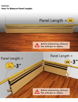
b1 Measure and mark from Square End of the Screen Track (side B) the Calculated Length.
b2 With a Hacksaw make a clean square cut through the Screen Track at the Cut Mark.
With a metal le, le down all sharp edges. Repeat steps for the other Screen Track
(side D) (see Figure 1).
b3 Measure and mark from each end of the Sill Adapter the Halved Calculated Length
so equal amounts are removed from both sides (see Figure 2).
b4 With the Hacksaw make a clean square cut through the Sill Adapter on both ends at the
Cut Marks. With a metal le, le down all sharp edges. Return to Measure on Page 2.
a1 To modify screen assembly to work in a Narrow Opening,
the Screen Tracks and Sill Adapter need to be cut down.
a2 Measure door opening width at top (W1), middle (W2), and
bottom (W3) from the inside of the exterior trim.
a3 Calculate Length of material to be cut o by taking the
narrowest width from above and subtracting it from 32
inches (see Example above).
a b
W3
W2
W1
SQUARE END
CALCULATED LENGTH
CUT MARK
SCREEN
TRACK
HACKSAW
APPENDIX - STEPS FOR NARROW OPENING AND SUPPORT BLOCKING FOR SILL (if required)
a1 Choose Support Blocking the width of the Door Sill with enough depth
to Extend ¾" Minimum out from the exterior trim Mounting Surface.
a2 Center the Support Blocking under the sill and make sure it is level and
parallel to the sill. Conrm it Extends ¾" Minimum from Mounting Surface.
a3 Properly secure Support Blocking below the Sill.
Return to Measure on Page 2.
Andersen retractable insect screens are designed to be installed
on the exterior of the home. However, the door can be installed on
the interior (i.e. for outswing door openings) as long as the opening
meets the sizing and mounting surface requirements.
Handle orientation can be reversed by unscrewing the Interior
Handle and reassembling in the rotated reversed conguration.
Take care to align the Latch Plate with the Handle Spindles when
reassembling. For more details, see gure 3 on Page 7.
a
SUPPORT
BLOCKING
DOOR SILL
APPENDIX B
–
Support Blocking for Door Sill
APPENDIX C
–
Outswing Door Openings
Screen Track (A/B) Screen Track (C/D)
Tape Measure
If opening width W1 = 29 ¾"
W2 = 29 ¾" and W3 = 29 ½"
Take narrowest width = 29 ½"
and subtract from 32 inches.
32 - 29 ½ = 2 ½ inches
The Calculated Length of
material to cut o is 2 ½
inches in this example.
For sill adapter (step b3), use
half the Calculated Length
by dividing it by 2.
2 ½ ÷ 2 = 1 ¼ inches
EXAMPLE
FOR STEP a3 BELOW
Sill Adapter
SILL ADAPTER
CUT MARK CUT MARK
HALF CALCULATED
LENGTH
HALF CALCULATED
LENGTH
MOUNTING
SURFACE
EXTEND
3/4" MIN
Metal File
Figure 1
Figure 2

7
RECEIVING TAB
SLIDES INSIDE SCREEN TRACK TUBING!
A
A
32
A
1. How do I open and close the insect screen?
Use the Handle to extend insect screen to the other side of door frame. It will
automatically latch when fully extended. Slide the Release Lever up or down
to unlatch, the insect screen will automatically retract (see Figure 1).
2. How do I lock and unlock the insect screen?
To lock the insect screen door, move the Lock Tab toward the screen assembly.
To unlock, move the Lock Tab away from the screen assembly (see Figure 2).
3. What should I do to maintain my retractable insect screen door?
The screen tracks will need occasional vacuuming to remove dirt and debris.
This will help keep the tracks clean and free of debris that may aect operation.
4. Can the handle be reversed so the locking tab is on the other side of the door?
The handle can be removed and reversed by unscrewing the Interior Handle and
reassembling in the rotated reversed conguration. Take care to align the Latch Plate
with the Handle Spindles when reassembling (see Figure 3).
5. Can the fastener clips be opened if I closed them in the wrong
position during installation?
You can open the fastener clip by applying downward pressure
with a at blade screwdriver until it releases open (see Figure 4).
6. Can replacement parts be purchased if something gets damaged on my door?
Parts can be purchased by visiting parts.andersenstormdoors.com or calling Customer
Service at 844-813-6664. It is helpful to have your serial number when ordering parts. The
serial number is located near Endcap A on your screen housing.
7. The door is not latching consistently, is there an adjustment that can be made?
The Striker can be adjusted to assist with more consistent latching of the unit. Loosen the
Striker Screws and slide the Striker up or down accordingly, retighten screws (see Figure 5).
8. What should I do with the unit in cold weather?
It is best for the unit to be stored in the retracted position during cold weather. We do not
recommend operating when temperatures are near or below freezing.
9. Why is the sill adapter narrower than the door opening?
The sill adapter provided is designed to avoid the need for cutting for most door opening
widths. A wider sill adapter can be ordered at parts.andersenstormdoors.com or by calling
Customer Service at 844-813-6664.
10. Is there a video available that will show me how to install and operate the door?
You can nd a video of how to install and operate the retractable insect screen door at
AndersenLuminAire.com/install
FREQUENTLY ASKED QUESTIONS – ANDERSEN
®
LUMINAIRE
™
RETRACTABLE INSECT SCREEN
For additional assistance visit
ANDERSENLUMINAIRE.COM or Customer Service: 844-813-6664
Figure 1
Unlatching Locking/Unlocking
Reverse Handle
Opening Fastener Clip
Striker Adjustment
Figure 2
Figure 3
Figure 4
Figure 5
INTERIOR
HANDLE
INTERIOR
HANDLE
INTERIOR
HANDLE
EXTERIOR
HANDLE
FASTENER CLIP IN CLOSED POSITION
STRIKER
SCREWS
RELEASE
LEVER
LOCK
TAB
HANDLE
SCREWS
HANDLE
SPINDLES
HANDLE
SPINDLES
LATCH
PLATE
FLAT BLADE SCREWDRIVER
STRIKER

8
LIMITED WARRANTY
ANDERSEN® LUMINAIRE™ RETRACTABLE SCREEN DOOR 5 YEAR LIMITED WARRANTY
LIMITED WARRANTY ON RETRACTABLE SCREEN DOOR COMPONENTS
Emco Enterprises LLC (Emco), an Andersen company, warrants the screen housing, latch housing, screen track, endcap and sill adapter
components of the Andersen® LuminAire™ retractable screen door to be free from defects in manufacturing, materials, paint adhesion, and
workmanship, under normal conditions, for five (5) years from the date of purchase or as long as the original consumer purchaser owns the
home in which the door was initially installed, whichever is shorter.
In the event a screen housing, latch housing, screen track, endcap or sill adapter fails as a result of a defect in manufacturing, materials or
workmanship within the limited warranty period specified above, and upon written proof of purchase, Emco, will at its option refund or
provide a replacement screen housing, latch housing, screen track, end cap or sill adapter without charge – installation is not included.
Such replacement is warranted for the remainder of the original limited warranty period. Please locate the door serial number and written
proof of purchase then contact Emco Consumer Support at 1-844-813-6664.
NO OTHER WARRANTIES OR REPRESENTATIONS
THIS LIMITED WARRANTY IS IN LIEU OF ALL OTHER WARRANTIES, EXPRESS OR IMPLIED, INCLUDING, BUT NOT LIMITED TO, ANY IMPLIED
WARRANTIES OF MERCHANTABILITY OR FITNESS FOR A PARTICULAR PURPOSE. ALL WARRANTIES ARE LIMITED TO THE APPLICABLE
STATUTE OF LIMITATIONS, BUT IN NO CASE WILL EXTEND BEYOND THE LIMITED WARRANTY PERIODS SPECIFIED ABOVE. EMCO EXCLUDES
AND WILL NOT BE LIABLE FOR ANY INCIDENTAL OR CONSEQUENTIAL DAMAGES, WHETHER ARISING OUT OF CONTRACT, TORT OR
OTHERWISE. THE REMEDY OF REPLACEMENT OF THE PRODUCT PROVIDED BY THIS LIMITED WARRANTY IS THE EXCLUSIVE REMEDY WITH
RESPECT TO AND ANY AND ALL LOSS OR DAMAGE.
APPLICABLE LAW
This Limited Warranty is only applicable in the U.S.A. (i.e. the fifty states and the District of Columbia). This Limited Warranty gives you
specific legal rights, and you may have other rights which vary from state to state or province. Some states do not allow the exclusion
or limitation of incidental or consequential damages or limitation of the duration of an implied warranty, so the above limitations or
exclusions may not apply to you. If any specific term of this Limited Warranty is prohibited by any applicable law, it shall be null and void,
but the remainder of this Limited Warranty shall remain in full force and effect.
WHAT IS NOT COVERED BY THIS LIMITED WARRANTY
Damage caused by:
• Improper installation (including failure to follow installation instructions), modification, maintenance, or use
• Chemicals or airborne pollutants, such as salt or acid rain
• Acts of God, including wind damage
• Accidents
• Normal wear and tear
• Products not manufactured by Emco
Emco Enterprises LLC is a wholly owned subsidiary of Andersen Corporation. Emco manufactures and supports the limited warranties
covering Andersen® and EMCO® Storm and Screen Doors. “Andersen” “EMCO” and all other marks where denoted are trademarks of
Andersen Corporation. ©2017 Andersen Corporation. All rights reserved.
Reprinted and effective as of September 12, 2017.
/