Page is loading ...

www. eldcontrols.com
Please retain these instructions after installation.
This device MUST be installed by a quali ed agency in accordance with the manufacturer's installation instructions. The de nition of
a quali ed agency is: any individual, rm, corporation or company which either in person or through a representative is engaged
in, and is responsible for, the installation and operation of HVAC appliances, who is experienced in such work, familiar with all the
precautions required, and has complied with all the requirements of the authority having jurisdiction.
READ THESE INSTRUCTIONS CAREFULLY AND COMPLETELY BEFORE PROCEEDING WITH THE INSTALLATION.
Installation Date:
Installed By: Phone:
P/N 46631000 08/20 Rev B
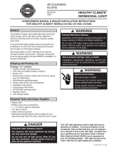
UV-AIRE™ AIR PURIFYING SYSTEM
Model: UV-13FM, 17FM
UV-C light inhibits the growth and reproduction of germs and bacteria that circulate through a homes’ heating
and air conditioning system. The treatment is a safe, silent, and proven way to make your home a healthier place
to live.
ITEMS INCLUDED IN KIT:
• Twin-Tube High-Output UVC Lamp
• 24 VAC Ballast* (UL listed)
• Lamp Cable with connector **
• FlexMount™ Articulating Bracket Assembly with Magnet (patent pending)
• Shield Assembly
• Snap-In Safety Viewport
• UV Hazard Warning Label
• Alcohol Wipe for Lamp
• Installation & Operation Manual
* 50 VA Transformer required (not included), order part # 46638900 TR50VA or equivalent.
** Some units may include a newer revision of the ballast that does not require the separate lamp
cable.
WARNING: Never expose eyes or skin to UVC light from any source. Looking directly at the UVC light may
cause permanent eye damage or blindness. Never operate the UV-Aire™ Air Purifying System out of the
plenum. Avoid touching the glass portion of the lamp with your hands.

WARNING: never expose eyes or skin to UVC light from any source. Looking directly at the UVC light may cause permanent eye damage or blindness.
Never operate the UV-Aire™ AirPurifying System out of the plenum. Avoid touching the glass portion of the lamp with your hands.
page 2 of 8
WARNING: Never expose eyes or skin to UVC light from any source.
• Looking directly at the UVC light may cause permanent eye damage or blindness.
• Never operate the UV-Aire™ Air Purifying System out of the plenum.
• Designed for a closed duct system. Do not mount near a supply or a return air opening.
• All duct openings in direct line of site of the UV light must be sealed with aluminum tape or equivalent
sealing methods.
WARNING: UV light will break down plastic materials not rated for UV exposure:
(Examples: wire insulation, ex duct, drain pans and humidi ers)
• The unit must be mounted at least 30" from the above stated type of materials.
• If it is necessary to mount the unit in direct line of sight of these types of materials, they must be shielded
with aluminum foil, aluminum foil tape, or sheet metal.
WARNING: DO NOT mount this unit outdoors.
• This product is designed for indoor installation only (i.e. attics, crawl spaces, basements, etc.).
This product is not sold as a medical device and is not for the purpose of diagnosis of any disease or condition
nor for use in the mitigation, treatment, or prevention of any disease or condition.
INDICATION FOR USE
There are di erent size units available, depending on the tonnage of your HVAC system. See chart below for
determining the needs of your home.
The FlexMount™ UV-Aire™ system is provided with a unique patent-pending, magnetically-attached Mounting
Bracket Assembly. The mounting bracket assembly may be rotated and/or extended relative to the mounting
surface, to provide maximum exibility in mounting positions and con gurations.
A re ective aluminum shield is included which may optionally be used to shield wiring, ductwork and parts
which could be damaged by UVC exposure, and/or concentrate the UVC rays in a particular area such as
the A-coil. The shield may be attached to the lamp bracket in four di erent positions, so that the bracket
assembly may be positioned in such a way as to create minimal obstruction to air ow, and provide maxim b
um exibility in positioning of the lamp relative to the bracket and mounting surface.
The part of the lamp bracket to which the lamp is attached may be separated from the mounting bracket
assembly, and used for mounting the lamp through a delta plate covering the end of the A-coil, or for
mounting the lamp inside of a plenum or air duct.
GENERAL INFORMATION
MODEL VOLTS AMPS HZ
WATTS
(LAMP)
MAX AIR TEMP °F
UVC INTENSITY
AT 1 METER
RECOMMENDED
HVAC TONNAGE
UV-13FM 24 1.5 50/60 24 190° 65 μW/cm2 1.5-3
UV-17FM 24 1.9 50/60 36 190° 110 μW/cm2 1.5-5
P/N 46631000 08/20 Rev B

WARNING: never expose eyes or skin to UVC light from any source. Looking directly at the UVC light may cause permanent eye damage or blindness.
Never operate the UV-Aire™ AirPurifying System out of the plenum. Avoid touching the glass portion of the lamp with your hands.
page 3 of 8
WARNING: Before installing or servicing a humidi er, air lter, heat system, or this unit, etc., always turn all
power OFF and have unit unplugged. Electrical shock can cause personal injury or death. Never expose eyes or
skin to direct UVC light from any source.
WARNING: To prevent water damage or electric shock, do not mount unit under a humidi er.
WARNING: Designed for a closed duct system. Do not mount near a supply or a return air opening.
WARNING: This product is designed for installation in the interior of weather-protected HVAC equipment or
ductwork, or on the exterior of protected ductwork only. For use on gas red, oil red, electric, split system
heat pump forced air systems*, and the interior of weather-protected heat pump packaged units**.
*Split system heat pumps are systems where the air handler and the air conditioning compressor are separate
units.
**Packaged units are systems where the air handler and the air conditioning compressor are built together and
are installed outside of the building
MAGNET MOUNT INSTALLATION INSIDE PLENUM OR AIR HANDLER
1. Choose a suitable location for the lamp in the supply plenum, return plenum, or air handler; preferably
downstream from the air lter. For optimum “cleaning” e ect on the A coil, mount the unit above or below the
A-coil as close as possible while still illuminating the entire surface of the coil. (See Figure 1)
2. Clean the mounting surface with degreaser and let dry. The mounting surface must be clean and dry.
3. Attach the Shield to the Mounting Bracket Assembly, if it is to be used, by bending
the tabs on the shield over the Lamp Bracket notches (see Figure 2). This will hold
the shield in place during installation and lamp replacement. The shield will be held
rmly in place when the lamp is installed.
Attach the Shield in the best of four possible positions, to shield sensitive wiring and
ductwork etc., and/or concentrate the UVC irradiation on a certain area or surface,
and allow positioning of the mounting bracket that creates minimal obstruction to
air ow.
4. Attach the Lamp to the Mounting Bracket Assembly with the supplied #8-32 wing
nuts (see Dimensional Drawing). Remove tag and alcohol swab from the lamp, and
clean the lamp glass with the alcohol swab. Avoid touching the cleaned lamp with
your hands.
5. Separate the Lamp Cable from the Ballast output cable connector, if attached. The cables have mating
watertight connectors to allow ease of installation and service (see Figure 3). Some newer ballasts do not
require the separate lamp cable and have the lamp connector built in.
6. Attach the Lamp connector to the lamp base, ensuring correct alignment of the rectangular pin arrangement.
The connector may be connected in either of two positions for which the pins line up. Ensure that the lamp
connector is rmly attached and that the sealing boot is pushed fully onto the lamp base.
Figure 1 - Typical Installation
Figure 2
P/N 46631000 08/20 Rev B

WARNING: never expose eyes or skin to UVC light from any source. Looking directly at the UVC light may cause permanent eye damage or blindness.
Never operate the UV-Aire™ AirPurifying System out of the plenum. Avoid touching the glass portion of the lamp with your hands.
page 4 of 8
7. Attach the Mounting Bracket Assembly to the mounting surface using the magnet. If the mounting surface
is insulated, slit the insulation, insert the magnet through the slit, draw the insulation back over the magnet
and bracket surface, and tape closed using metal tape or other means that would not be a ected by UVC rays.
Some surfaces may be inadequate for mounting with the magnet (rough, uneven, heavy paint etc.). The magnet
may be removed from the Mounting Bracket Assembly, and the bracket assembly attached to the mounting
surface with included sheet metal screws or other appropriate fasteners. Holes are provided on the bracket
assembly for this purpose. Use care to avoid equipment damage to concealed wiring and other components
when installing fasteners.
8. If desired, loosen the wing nut on the bottom of the Mounting Bracket Assembly (see Dimensional Drawing),
and swivel/extend the lamp bracket to position the lamp in the desired position, and retighten the wing nut
securely.
CAUTION: MAKE CERTAIN THAT POWER HAS BEEN DISCONNECTED TO THE HVAC SYSTEM, AND THE 24
VAC TRANSFORMER POWER SOURCE, BEFORE PROCEEDING WITH THE INSTALLATION!
9. Mount the 50VA, 24VAC transformer (not included) in an area protected from the lamp, using the included
sheet metal screws or other appropriate fasteners, and connect to 120V power source. Observe all local and
national electrical and mechanical code requirements regarding 120 V wiring
NOTE: It is recommended that the 120V transformer power source be wired through a safety disconnect
switch, such as a door switch, that will disconnect power to the transformer if the access panel to the UVC
lamp installation area is removed (see Wiring Diagram). If such a switch is not present on the equipment, it is
recommended that a door interlock switch (not included, min. 3A 24VAC rating) be installed and wired into the
24VAC ballast power circuit (see Wiring Diagram).
10. Mount the Ballast using the included sheet metal screws or other appropriate fasteners, in a location close
enough to connect the 24VAC ballast power cable to the 24VAC transformer (not included), and to connect the
ballast output cable to the lamp cable connector, or directly to the lamp depending on the ballast. If the ballast
is not in a location protected from UVC exposure, protect the ballast with the included shield, or by fabricating
and installing a sheet metal shield or equivalent. DO NOT wrap the ballast in tape or cover the ballast with
anything that would insulate or reduce the ability of the ballast to dissipate heat.
11. Route the Ballast output cable (watertight connector on the end) to mate with the Lamp Cable, and provide
su cient support to prevent entanglement with other components (such as a blower wheel or removable panel
fasteners), and reduce stress on the Mounting Bracket Assembly. If ballast does not
have the connector, skip to step 13.
12. Connect the Lamp Cable connector to the matching connector on the Ballast
output cable and ensure that the connectors are fully mated. These connectors are
designed to prevent misalignment of the mating connectors; line up the projecting
tabs of both connectors to allow connection (see Figure 3).
13. Connect the Ballast 24 VAC power cable to the 24 VAC transformer secondary
(output) terminals (see Wiring Diagram), or the alternate installer-supplied door
interlock switch if used. Secure the cable to prevent entanglement with other
components (such as a blower wheel or removable panel fasteners).
Figure 3
P/N 46631000 08/20 Rev B
* not included on newer version of ballast.

WARNING: never expose eyes or skin to UVC light from any source. Looking directly at the UVC light may cause permanent eye damage or blindness.
Never operate the UV-Aire™ AirPurifying System out of the plenum. Avoid touching the glass portion of the lamp with your hands.
page 5 of 8
14. Identify an area of the access panel or other area of the equipment or duct through which the lamp may be
seen. Verify that the surface is free of dirt, oil, and other contaminants, peel of the label backing and apply the
Safety label to the surface such that the warning information is clearly visible (see Figure 8).
15. Drill a 3/8” hole through the center of the Safety Label, where indicated by the dashed circle (see gure 7).
16. Snap the clear plastic Safety Viewport into the hole (see Figure 8). The lamp may be safely viewed through
the viewport while it is lit.
17. Verify that all electrical connections are tight and that the lamp and bracket is secure.
18. Replace all access panels and other items that may have been removed during the installation, such as
electrical box covers, etc.
19. Verify that the Safety Viewport is securely fastened in the hole drilled through the Safety Label.
WARNING: BEFORE RESTORING POWER TO THE HVAC SYSTEM OR THE TRANSFORMER POWER SOURCE,
VERIFY THAT NO OPENINGS EXIST THROUGH WHICH UVC RAYS FROM THE LAMP MAY ESCAPE. VERIFY
THAT ALL ACCESS PANELS AND DUCTWORK ETC. HAVE BEEN REPLACED AND SEALED IF NECESSARY,
AND THAT THE SAFETY VIEW PORT IS SECURELY FASTENED IN PLACE.
20. Restore power to the HVAC system and the transformer power source. Look through the Safety Viewport
to verify that the lamp is lit.
BRACKET MOUNT INSTALLATION THROUGH A-COIL DELTA PLATE OR PLENUM
If the lamp is to be mounted externally on the plenum or an air duct, or if the lamp is
to be mounted through a delta plate (covers the end of A-coil in certain air handler
designs), follow these steps for installation:
1. Separate the lamp mounting portion of the Lamp Bracket from the remainder
of the lamp bracket (see Figure 4), by bending back and forth or cut with snips or
hacksaw.
2. Attach the shield to the separated bracket, on the side opposite from the lamp
mounting studs (see Figure 5), if it is to be used. Any of the four attachment positions
may be used.
3. Insert the lamp through the oval hole in the bracket and shield base, and attach
to the mounting studs using the supplied #8-32 locking nuts (see Figure 5). Do not
use the supplied #8-32 wingnuts, unless the lamp is to be installed inside an air
handler or other equipment or structure requiring the use of a tool to access.
4. Mark the location for the lamp, and drill or cut a 2” round hole (may be an oval hole 2” x 1” if the shield is not
used) in the mounting surface, using care to avoid damage to equipment or concealed wiring. If the lamp is
to be mounted on duct board, fabricate a mounting surface by cutting a 6” x 6” square of suitable sheet metal.
Cut the hole for the lamp in the sheet metal and the duct board, and tape the sheet metal securely to the duct
board using mastic-backed metal tape.
5. Insert the lamp through the hole, orient the lamp such that it presents the least obstruction to air ow or
that the shield is in proper position, and secure the bracket to the mounting surface using three of the supplied
sheet-metal screws, or other appropriate fasteners.
6. If mounting through the exterior of a plenum or air duct, use metal duct sealing
tape (not included) to tape around the edges of the mounting bracket, to prevent
UVC rays from escaping and prevent duct leakage.
7. Position the cable clamp installed on the Lamp Cable such that the clamp
hole is aligned with the fourth hole in the bracket, and install the fourth screw or
fastener through the clamp and bracket, into the mounting surface (see Figure 6).
Figure 4
Figure 5
Figure 6
P/N 46631000 08/20 Rev B
Note: This step is important to preclude the inadvertent removal of the lamp from the bracket before
disconnecting the lamp cable from the lamp.

WARNING: never expose eyes or skin to UVC light from any source. Looking directly at the UVC light may cause permanent eye damage or blindness.
Never operate the UV-Aire™ AirPurifying System out of the plenum. Avoid touching the glass portion of the lamp with your hands.
page 6 of 8
CAUTION: MAKE CERTAIN THAT POWER HAS BEEN DISCONNECTED TO THE HVAC SYSTEM, AND THE 24
VAC TRANSFORMER POWER SOURCE, BEFORE PROCEEDING WITH THE INSTALLATION!
8. Follow steps 9-20 in the Magnet Mount Installation section to complete the installation (see Figures 7,
8, 9).
WARNING: BEFORE RESTORING POWER TO THE HVAC SYSTEM OR THE TRANSFORMER POWER SOURCE,
VERIFY THAT NO OPENINGS EXIST THROUGH WHICH UVC RAYS FROM THE LAMP MAY ESCAPE. VERIFY
THAT ALL ACCESS PANELS AND DUCTWORK ETC. HAVE BEEN REPLACED AND SEALED IF NECESSARY, AND
THAT THE SAFETY VIEW PORT IS SECURELY FASTENED IN PLACE.
Figure 9
Figure 8
Figure 7
MAINTENANCE
1. Inspect and clean lamp at least every 6 months.
2. Replace your UV-Aire™ Air Purifying System lamp once a year to maintain the lamps maximum output
intensity. The lamp should operate continuously for maximum lamp life and light e ectiveness.
LAMP REPLACEMENT PROCEDURE
WARNING: DISCONNECT 120V POWER TO THE 24VAC TRANSFORMER BEFORE PROCEEDING WITH LAMP
REPLACEMENT OR OTHER MAINTENANCE. IF THE LAMP IS MOUNTED EXTERNALLY ON A PLENUM OR
AIR DUCT, DISCONNECT THE LAMP CABLE FROM THE LAMP BEFORE REMOVING THE LAMP FROM THE
EXTERNAL MOUNT BRACKET. VERIFY THAT THE LAMP IS NOT LIT BY LOOKING THROUGH THE SAFETY
VIEWPORT BEFORE REMOVING ANY ACCESS PANELS, OR THE LAMP FROM THE EXTERNAL MOUNT BRACKET.
1. Verify that the lamp is not lit by looking through the safety viewport.
2. Disconnect the Lamp Cable connector from end of lamp.
3. Remove the nuts holding the lamp on the mounting bracket and remove the lamp, using care to avoid
breaking the lamp.
NOTE: When replacing the lamp, always wipe o lamp before installing.
4. Install the replacement lamp onto the mounting bracket and tighten the nuts. Tip: leave the protective
packaging sleeve on the lamp (magnet mount only) on the lamp until the replacement procedure is complete,
to help protect the lamp from breakage.
NOTE: UV lamps contain a small amount of mercury, like a typical uorescent lamp. Check with your local waste
management authority for local disposal or recycling requirements. According to the EPA’s Universal Waste
Rule, these types of lamps may be disposed of into household waste.
5. Attach the Lamp Cable connector onto the end of the lamp.
6. After replacing lamp, make sure a new UV Hazard Warning Label (supplied with lamp replacement) is applied
to the HVAC equipment or ducting and dated with the date of installation.
7. Restore power to the HVAC system and the transformer power source. Look through the Safety Viewport to
verify that the lamp is lit.
P/N 46631000 08/20 Rev B

WARNING: never expose eyes or skin to UVC light from any source. Looking directly at the UVC light may cause permanent eye damage or blindness.
Never operate the UV-Aire™ AirPurifying System out of the plenum. Avoid touching the glass portion of the lamp with your hands.
page 7 of 8
TROUBLESHOOTING GUIDE
1. If the lamp does not light up, replace the lamp.
2. If the lamp still does not light up after replacing the lamp, replace ballast.
REPLACEMENT PARTS LIST
MODEL LAMP P/N BALLAST P/N
UV-13FM 46632513
46635900
UV-17FM 46632517
OPTIONAL ACCESSORY PARTS LIST
MODEL DESCRIPTION PART NUMBER
TR50VA
Transformer
120-208 -240V Primar y
24VAC,50 VA
Universal Mount
46638900
P/N 46631000 08/20 Rev B

Phone: 252.522.3031 • Fax: 252.522.0214
www.fieldcontrols.com
© Field Controls, LLC P/N 46631000 08/20 Rev B
This manual may be downloaded and printed from the Field Controls website (www. eldcontrols.com)
This manual may be downloaded and printed from the Field Controls website (www. eldcontrols.com)
WARRANTY
WARRANTY
For warranty information about this or any Field Controls product, visit:
For warranty information about this or any Field Controls product, visit:
www. eldcontrols.com
www. eldcontrols.com
Field Controls Technical Support
Field Controls Technical Support
1.800.742.8368
1.800.742.8368
eldtec@ eldcontrols.com
eldtec@ eldcontrols.com
/