Page is loading ...

Page 1
THESE INSTRUCTIONS MUST BE LEFT WITH THE
HOMEOWNER FOR FUTURE REFERENCE
General
The Healthy Climate® germicidal light emits ultraviolet
(UVC) energy that has been proven effective in reducing
microbial life forms (viruses, bacteria, yeasts, and molds)
in the air.
UVC germicidal lamps greatly reduce the growth and pro-
liferation of mold and other bio-aerosols (bacteria and vi-
ruses) on illuminated surfaces.
Germicidal lamps are NOT intended to be used for remov-
al of active mold growth. Existing mold growth must be
appropriately removed PRIOR to installation of the germi-
cidal lamp.
Models covered by this document include UVC-24V, UVC-
41W-S and UVC-41W-D.
Shipping and Packing List
Contents
1 - Healthy Climate® germicidal light consisting of:
1 - UVC lamp (2 lamps for model UVC-41W-D)
1 - Enhanced ballast
2 - 8-32 x 1/2” sheet metal screws for enhanced ballast
1 - Lamp holder assembly (2 lamp holders for model
UVC-41W-D)
3 - 6-20 x 1/2” sheet metal screws per lamp holder as-
sembly
1 - Mounting template
2 - UVC danger labels
1 - Installation instructions
1 - Warranty sheet
1 - Product registration card
WARNING
Improper installation, adjustment, alteration, service
or maintenance can cause property damage, personal
injury or loss of life. Installation and service must be
performed by a licensed professional HVAC installer or
equivalent, service agency, or the gas supplier.
CAUTION
As with any mechanical equipment, contact with sharp
sheet metal edges can result in personal injury. Take
care while handling this equipment and wear gloves and
protective clothing.
Required Tools and Supplies
• Drill
• Phillips screw bit or screwdriver
• 1" (25mm) hole cutter
• Cotton cloth and gloves
Part No. Replacement Part Description
Y0390 UVC lamp for UVC-24V (Blue Tip)
Y0391 UVC lamp for UVC-41W-S & UVC-41W-D
(Green Tip)
91W54 UVC lamp holder base (all models)
Y0392 UVC lamp holder assembly (all models)
Y0393 Enhanced ballast for UVC-24V
Y0394 Enhanced ballast for UVC-41W-S
Y0395 Enhanced ballast for UVC-41W-D
Y5171 Lamp shielding bafe
42J32 Transformer (40VA rating)
WARNING
Electric Shock Hazard! – Disconnect all
power supplies before servicing.
Replace all parts and panels before
operating.
Failure to do so can result in death or
electrical shock.
INDOOR AIR QUALITY PRODUCTS
KITS AND ACCESSORIES
506038-01
8/2018
Supersedes 9/2017
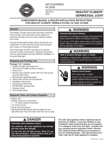
HEALTHY CLIMATE®
GERMICIDAL LIGHT
INSTALLATION & HOMEOWNERS INSTRUCTIONS FOR HEALTHY CLIMATE®
GERMICIDAL LIGHT – MODELS UVC-24V, UVC41W-S & UVC-41W-D
UVC LAMP INSTALLED
UVC-24
UVC-41W-S
UVC-41W-D

Page 2
WARNING
Potential Mold Spore Release.
Application of UVC lamps to existing mold growth can
cause respiratory irritation and allergic symptoms.
Do not use UVC lamps where active mold growth exists.
Remove active mold growth from surfaces prior to
operation of UVC lamps.
DANGER
Ultraviolet (UVC) Radiation Hazard.
Any exposure will cause signicant eye damage and
may cause skin damage.
DO NOT look into UVC light source.
Access panels must be in place during appliance
operation.
Dimensions/Specifications
Dimensions Model UVC-24V (X9423) Model UVC-24V
Model UVC-41W-S
Model UVC-41W-D
ENHANCED
BALLAST
11-3/4”L x
2-3/4”W x
1-5/8”H
15-1/4”
2-1/4”
ENHANCED
BALLAST
4-3/4”L x
2-1/4”W x
2”H
Connector
15-1/4”
2-1/4”
Connector
Lamp
Lamp
15-1/4”
2-1/4”
15-1/4”
2-1/4”
ENHANCED
BALLAST
11-3/4”L x
2-3/4”W x
1-5/8”H
Connector
Lamp
Connector
Lamp
Enhanced ballast 4.75”L x 2.25”W x 2”H
(121mm x 58mm x 51mm)
Lamp 3/4””dia. x 16” length.
(19mm x 406mm)
Dimensions Models UVC-41W-S (X9424) and
UVC-41W-D (X9425)
Enhanced ballast 11.75”L x 2.75”W x 1.625”H
(300mm x 70mm x 42mm)
Lamp 3/4””dia. x 16” length.
(19mm x 406mm)
Electrical Power Supply
UVC-41W-S & UVC-41W-D 110V/230V Universal, 50/60 Hz
UVC-24V 24V, 50/60 Hz
Power Consumption
UVC-41W-S 41 Watts
UVC-41W-D 82 Watts (41Watts each lamp)
UVC-24V 24 Watts (24VA required for
transformer)
Lamp Operating Temperature
ALL MODELS -15ºF to 180ºF (-15ºC to 82ºC)
Enhanced Ballast Operating Temperature
ALL MODELS 45ºF to 150ºF (7ºC to 65ºC)
Accessories
ALL MODELS Shielding Baffle (Y5171)
Power Cordage (from connector to enhanced ballast)
ALL MODELS 6 feet length
Listings:
FIFRA (Federal Insecticide Fungicide Rodenticide Act) - File No. 73316.
U.S. Patent Nos. 5,334,347, 5,817,276, 6,245,293, 6,267,924, 6,280,686, 6,313,470, 6,627,000, 6,539,727, 6,932,494, 6,550,257.
Specifications subject to change without notice.
LAMP
POWER
Model UVC-24V
Input: 24V, 50/60Hz, 1.0A.
Open Circuit Voltage 600Vdc.
Class P, TYPE 1, SOUND RATING: A
*RS* ELECTRONIC BALLAST
Only use replacement UV lamp #Y0390.
Only use replacement power supply #Y0393.
Install in accordance with National Electric
Code Suitable for air handling use only
ETL LISTED
CONFORMS
TO UL STD
1598
MODEL NAMEPLATES APPLIED TO THE BALLAST FOR FIELD IDENTIFICATION

Page 3
Usage, Location and Other Requirements
Air Handler Size Requirements
UVC Light Model Air Handler Size (Tonnage)
UVC-24V 1-5
UVC-41W-S 3-5
UVC-41W-D 3-5
*In UVC-41-W-D model, only one light can be installed in
the delta plate.
Selecting an Installation Location
This device has been designed to t into a wide variety of
locations. Choose a location with enough clearance to al-
low the UVC lamp to be removed and replaced easily. Be
sure to choose a location that is easy to access for main-
tenance and that has an electrical power supply nearby.
See Figure 1 for preferred furnace locations; see g-
ure 2 for preferred air handler locations.
Install the device in the return air duct, at the furnace, near
the HVAC coil, or in the supply air duct. Duct depth must
be at least 16" (406mm) to allow for the lamp length.
OPTIMAL POSITION FOR COIL MOUNTING
When installing the light in a coil with a knockout, use the
knockout. The knockout is located in the optimal position
for the UVC light (where shown in gure 1). For coils with-
out knockouts, and depending on the space available, AL-
WAYS try to locate the light’s mounting position as near
the “optimal location” as possible.
Special Installation Notes:
• Do not install in closet return applications where light
will be seen.
• Do not install a bulb in the access door or blower com-
partment.
• Do not install in rooftop/outdoor applications.
• Do not expose wiring or plastic parts to UVC light. Do
not install device beneath a humidier or source of wa-
ter.
• If the UVC device is installed near an air lter, check
with lter manufacturer for UVC resistance properties
and/or use the shielding bafe to protect the air lter.
• A shielding bafe is required for non-UVC resistant
lters, which includes Healthy Climate lters.
PLENUM
UVC LIGHT
IN-LINE SERVICE DISCONNECT
UVC LIGHT (shown in “optimal” mounting position)
ELECTRICAL
JUNCTION
BOX
110/230V
ENHANCED
BALLAST
IN-LINE
SERVICE
DISCONNECT
UVC-41W-D
24V
ENHANCED
BALLAST
24V STEP
DOWN
FORMER
FIGURE 1. Preferred UVC Light Mounting Locations (Furnace Applications)

Page 4
NOTE - If UVC lamp is installed directly above air filter, a shielding baffle MUST be used.
NOTE - Installer to use dimples for locating additional knockouts for added circuits.
24V ENHANCED
BALLAST
24V STEP DOWN
TRANSFORMER
IN-LINE
SERVICE
DISCONNECT
UVC-24V
UVC LIGHT (shown in “optimal” mounting position)
IN-LINE
SERVICE
DISCONNECT
110/230V
ENHANCED
BALLAST
ELECTRICAL
JUNCTION
BOX
UVC LIGHT
PLENUM
PLENUM
DIMPLES 2" & 4" BACK FROM
THE KNOCKOUT (SEE NOTE)
FIGURE 2. Preferred UVC Light Mounting Locations (Air Handler Applications)

Page 5
Installation
Installing the Enhanced Ballast
The enhanced ballast must be installed on a solid surface
and where the LEDs are visible (see gure 1 for preferred
location). Attach the enhanced ballast using included
sheet metal screws (see gure 3).
110/230V ENHANCED
BALLAST
8-32 x 1/2"
SHEET
METAL
SCREWS
8-32 x 1/2"
SHEET
METAL
SCREWS
24V ENHANCED
BALLAST
LAMP LEDS
(BLUE indicates
lamp operation)
POWER AND
LAMP LEDS
POWER LED (GREEN indicates
power ON)
FIGURE 3. Install the Enhanced Ballast
NOTICE
The enhanced ballast must be installed in compliance
with all national and local electrical and mechanical
codes. Failure to do so will void warranty.
Flexible duct installation with less than 6 ft. (1.8m) clear-
ance between the lamp and the ex duct must have a 90
degree metal elbow and 6’ of metal duct installed to pro-
tect the duct from direct UVC light exposure (see gure 4).
FLEXIBLE DUCT
90-DEGREE METAL ELBOW
UVC
LIGHT PLENUM
6' METAL DUCT
FIGURE 4. 90-Degree Elbow Installation
WARNING
Potential Risk of Fire.
Dust, lint and other debris may cause re if allowed to
come in contact with illuminated UVC lamp.
Remove any dust, lint or other debris from lamps and
surrounding duct system.
CAUTION
Potential Risk of Degradation of Materials.
Potential of degraded wire insulation may cause human
injury through electrical shock.
UVC light may damage plastics and rubber materials.
May cause fabric discoloration.
Avoid UVC light exposure to plastic drain pans, wire
insulation, ex duct or other plastic/rubber components.
Before installation, conrm that any corrosion-resistant
coating (if applied to the coil) will not be negatively
impacted by the UVC light exposure.
Preparation for Lamp Holder Base Installation
NOTICE
Do not damage components of the heating system or
refrigerant tubing when drilling or cutting.
Coil Delta Plate Applications (Preferred)
1 - If there is a knockout hole on the coil delta
plate for UVC lamp application (on some
models), knock out the 1" hole for the lamp.
OR, if there is no knockout hole on the coil delta
plate, use the provided template (also shown in
gure 5) as a guide to identify a hole location as
close as possible to the optimum delta plate location
which is about 1/3 from the bottom of the coil as
shown in gure 1. Be sure that the lamp cable will
not interfere with surrounding tubing. Be sure to
allow 30 degrees rotational clearance for installing
and locking the lamp holder in the base. When an
appropriate location is identied, drill a 1" hole for
the lamp. DO NOT drill the mounting holes for
the holder at this time!
2 - Skip this step if no shielding bafe is required.
When using a shielding bafe (Y5171), it must
be installed in the 1" hole prior to continuing this
procedure. See the procedure described in gure 6.
3 - Align the template over the 1" hole. (If the bafe is
used, this procedure will drill holes through both
the bafe and the delta plate.) Use the template to
mark three hole locations on the mounting surface.
Remove the template and drill three 3/32" pilot
holes for mounting screws.

Page 6
NOTICE: Orient cable
away from obstructions.
Rotate template as
needed.
LOCK POSITION
ALIGN
POSITION
LAMP
BASE
LAMP
HOLDER
1" HOLE
DRILL (3) 3/32"
HOLES
ROTATE TO LOCK
FIGURE 5. Using the Mounting Template
Plenum Applications
NOTE - Duct board plenum installations are not recom-
mended.
1 - Place the mounting template label in the desired
location. Using the template as a guide, drill a 1"
hole for the lamp.
2 - Skip this step if no shielding bafe is required.
When using a shielding bafe (Y5171), it must
be installed in the 1" hole prior to continuing this
procedure. See the procedure described in gure 6.
3 - Align the template over the 1" hole. (If the bafe is
used, this procedure will drill holes through both
the bafe and the plenum.) Use the template to
mark three hole locations on the mounting surface.
Remove the template and drill three 3/32" pilot
holes for mounting screws.
Installing the Shielding Bafe
Install the lamp shielding bafe when installing light above
a non-UVC resistant component, such as a lter. Adjust
the bafe to ensure the component is not subject to direct
UVC light. Install the shielding bafe (ordered separately)
as shown in gure 6.
IMPORTANT - Shielding bafe must be used in air han-
dler applications where the lter would be exposed to
direct UVC light.
SHIELDED AREA
INSERT SHIELDING
BAFFLE INTO 1"
KNOCKOUT OR
DRILLED HOLE
USE ANY TWO OF THE CORNER HOLES TO SECURE THE BAFFLE TO THE
MOUNTING SURFACE. USE FIELD-PROVIDED SHEET METAL SCREWS.
HOLD BASE OF BAFFLE FLUSH TO THE
MOUNTING SURFACE. ALLOW TROUGH
TO REST ON BOTTOM OF 1" HOLE.
BE SURE THE SHIELD IS IN THE POSITION WHERE
SHIELDING FROM UVC LIGHT IS REQUIRED.
1
3
4
CLASP
TROUGH
2
1-INCH
HOLE
TROUGH
SHIELDED AREA
FIGURE 6. Install the Shielding Bafe
Installing the UVC Light
NOTE - If a shielding bafe (Y5171) is required, it must
be installed and properly positioned, and the lamp base
mounting holes must be located and drilled prior to instal-
lation (see gures 5 and 6).
1 - Separate the lamp base from the lamp holder. Place
the lamp base on the mounting surface and attach
with three provided #6-20 x 1/2” sheet metal screws
(see gure 7).
LAMP BASEMOUNTING
SCREWS
1 INCH
HOLE
FIGURE 7. Install Lamp Base

Page 7
CAUTION
Lamps Contain Mercury.
Ingestion or contact with mercury or mercury vapor is
hazardous to your health.
Take care when handling lamps. If lamp is broken, avoid
contact with mercury.
NOTICE
Clean lamps prior to installation using a cotton cloth to
remove dirt and ngerprints.
Failure to clean lamps could shorten the lamp’s life span.
2 - Observing the CAUTION and the NOTICE above,
clean the lamp before installing.
3 - Noting the orientation of the pins for lamp insertion,
fully insert the lamp into the lamp holder socket so
that the o-ring is fully inside the lamp holder (see
gure 8).
INSERT LAMP INTO THE SOCKET ON
THE LAMP HOLDER. BE SURE O-RING
ON LAMP PLUG END (SEE DETAIL) IS
FULLY ENGAGED IN THE LAMP
HOLDER.
LAMP
BASE
IMPORTANT! MAKE SURE BAND IS LOCATED
IN THE CENTER OF THE LAMP
O-RING PLUG END OF LAMP
LAMP
HOLDER
FIGURE 8. Inserting Lamp into Socket
4 - Be careful not to disturb the band in the center of
the lamp. Insert the assembled lamp holder into
the lamp base. If lamp shielding bafe is used –
be sure the far end of the lamp rides in the bafe’s
trough and engages in its clasp (see gure 9).
BAFFLE
TROUGH
LAMP
SCREWS
MOUNTING
SURFACE
LAMP BASE
GUIDE LAMP TIP ALONG
THE SURFACE OF THE
TROUGH
LAMP
HOLDER BAND
CLASP
FIGURE 9. Guiding Lamp into Shielding Bafe
5 - Align arrow on lamp holder with arrow on lamp base.
Insert lamp holder into base (see A in gure 10).
6 - Twist to align lamp holder arrow with lock symbol
(see B in gure 10).
LAMP
BASE
APPROX.
30 DEG.
ROTATION
AB
FIGURE 10. Locking Lamp in Place
7 - Connect the lamp holder cord’s quick connect to the
mating-enhanced ballast connector (see gure 11).
ENHANCED
BALLAST
CORD
LAMP CORD
CONNECTOR
PROPER
SEATING
FIGURE 11. Connect Lamp Cord to Enhanced
Ballast Cord (Connector)

Page 8
Power Source
IMPORTANT
The UVC light must remain ON at all times. It must NOT
be connected to a switched power source and must
NOT be wired to come on or go off with blower.
Connect Power and Check Operation
On the UVC-41W-S and UVC-41W-D models, connect
unswitched 110/230 volt power to the junction box. The
junction box should be connected to a maximum 20 amp
circuit breaker. If power source is on a circuit breaker
greater than 20 amp, include a maximum 20 amp in-line
fuse or safety switch / disconnect with maximum 20 amp
fuse before the ballast wires are connected to the junction
box. From there, 110/230 volt power connects directly to
the UVC light’s enhanced ballast as described below.
Check VA Capacity – (For UVC-24V Model only). If using
the transformer in the air handler, be sure that the trans-
former has adequate VA capacity to power the 24VA lamp.
If the air handler’s transformer does not have the VA ca-
pacity, install a dedicated transformer with VA capacity to
power the light.
Connect the enhanced ballast cord to the 24V step down
transformer (see gure 13).
To connect the 24V light to the air handler control, connect
the power cord black wire to “R” terminal and the white
wire to “C” terminal on the control and the green wire to
ground in the cabinet.
Check that Power and Lamp LEDs are operating. Turn off
room lights while the UVC germicidal lamp is operating
and the access panels are in place. Make sure that blue
light is NOT visible through supply or return air grilles,
holes in ducts, leaks around access panels, etc. If blue
light is visible, either seal leaks around doors or panels or
reposition the UVC lamp so that no light is visible. If it is
not possible to completely avoid exposure to UVC light,
the germicidal light must be removed.
Danger Label Application
Install UVC Danger label (see gure 12) to air handler
access panel so it is clearly visible. Install the additional
Danger label near location of potential exposure for UVC-
41W-D.
DANGER
Ultraviolet (UVC) Radiation Hazard.
Any exposure will cause signicant eye damage and
may cause skin damage.
DO NOT look into UVC light source.
Access panels must be in place during appliance
operation.
Disconnect power cord from UVC light appliance before
servicing the UVC light, the air handling equipment or
the duct system.
FIGURE 12. Example of the Danger Label
UVC-41W-S / -D Models
UVC-24V Model
CONNECT ENHANCED BALLAST
CORD TO 24V TRANSFORMER
CONNECT ENHANCED BALLAST
CORD LEADS TO 110/230V
24V STEP DOWN TRANSFORMER
ELECTRICAL JUNCTION BOX
24V
ENHANCED
BALLAST
CORD
CORD
110/230V ENHANCED BALLAST
POWER AND LAMP LEDS 110/230V UNSWITCHED POWER SOURCE
110/230V UNSWITCHED
POWER SOURCE WITH
MAXIMUM 20 AMP CIRCUIT
BREAKER
FIGURE 13. Preferred Power Connections

Page 9
Operation
For optimal performance, continuous operation of the
UVC germicidal lamp is recommended.
Maintenance
For all maintenance, contact a qualied HVAC technician.
LED(s) Not Illuminated
Power status LED not lit – Check that the lamp unit is con-
nected to the proper power source.
Lamp status LED(s) not lit –
1 - Check that the lamp holder and the enhanced
ballast connectors are properly engaged.
2 - Check that lamp holder is properly engaged in the
base.
3 - Check that lamp is properly connected to lamp
holder.
4 - Ohm-check across the lamp pins to check for
continuity of lamp laments.
Troubleshooting charts are provided to aid in determining
the cause of any problems encountered (gures 14 and
15).
Annual Lamp Replacement
The lamp should be replaced every 12 months, as UVC
energy production diminishes over time.
1 - Obtain the correct replacement lamp for your
Healthy Climate® germicidal light model.
2 - Disconnect power to the lamp holder by unplugging
the connector.
3 - Twist open the lamp holder and carefully withdraw
the lamp. Allow lamp to cool 10 minutes before
touching.
4 - Wear cotton gloves or use a cotton cloth when
handling the new lamp. Remove the old lamp and
install the new lamp in the lamp holder.
5 - Carefully insert the assembled lamp and holder.
6 - Twist to close the lamp holder.
7 - Reconnect power to the lamp holder.
8 - Use LED indicator to verify operation.
Lamp Disposal
Hg-LAMP Contains Mercury – Manage in accordance
with local, state and federal disposal laws. Refer to www.
lamprecycle.org or call 1-800-953-6669.
Lamp Breakage
Wear protective gloves, eye wear and mask.
Sweep the broken glass and debris into a plastic bag, seal
the bag, and dispose of properly. Contact your local waste
management ofce for proper disposal.
Do not use a vacuum cleaner. Do not incinerate.
WARNING
Personal Burn Hazard.
Personal injury may result from hot lamps. During
replacement, allow lamp to cool for 10 minutes before
removing lamp from xture.

Page 10
DANGER
Ultraviolet (UVC) Radiation Hazard.
Any exposure will cause signicant eye damage and may cause skin damage.
DO NOT look into UVC light source.
Access panels must be in place during appliance operation.
FIGURE 14. UVC Light Troubleshooting – Power

Page 11
DANGER
Ultraviolet (UVC) Radiation Hazard.
Any exposure will cause signicant eye damage and may cause skin damage.
DO NOT look into UVC light source.
Access panels must be in place during appliance operation.
FIGURE 15. UVC Light Troubleshooting – Lamp

Page 12
Checklist for Complete Installation and Safety Items
customer copy
Installation Procedure or Safety Item
All items were included in the shipping box and have been installed (see Shipping and Packing list).
Danger label installed on door to air handling unit (see figure 12).
Shielding baffle has been installed to protect filter or other non-UVC resistant components (see figure 6).
Additional Danger label installed, if necessary (see figure 12).
NOTE - If exposure to the UVC light is possible in any other situation (e.g. when duct panel is removed), you MUST install the
closed Danger label in a visible location near the site where exposure may occur.
Turn off room lights while the UVC germicidal lamp is operating and the access panels are in place. Make sure that blue light IS NOT visible
through supply or return air grilles, holes in ducts, leaks around access panels, etc.) If blue light is visible, either seal leaks around doors or
panels or reposition the UVC lamp so that no light is visible. If it is not possible to completely avoid exposure to UVC light, device must
be removed.
Be sure to have explained to the customer the danger of viewing UVC germicidal light. Make sure the customer understands the possibility of
significant eye damage/blindness or serious skin damage. Should the customer detect any blue light from the unit, the customer must know to
immediately contact the technician for service and be sure no one goes near enough to the source of the light to look at, or be exposed to the
light.
Checklist has been filled out and left with homeowner.
All instructions and safety instructions have been followed and the checklist is completed.
Installation Te chnician Signature:
Date:
Customer Signature:
Date:
Cut along line and return bottom copy to dealer
Checklist for Complete Installation and Safety Items dealer copy
Installation Procedure or Safety Item
All items were included in the shipping box and have been installed (see Shipping and Packing list).
Danger label installed on door to air handling unit (see figure 12).
Shielding baffle has been installed to protect filter or other non-UVC resistant components (see figure 6).
Additional Danger label installed, if necessary (see figure 12).
NOTE - If exposure to the UVC light is possible in any other situation (e.g. when duct panel is removed), you MUST install the
closed Danger label in a visible location near the site where exposure may occur.
Turn off room lights while the UVC germicidal lamp is operating and the access panels are in place. Make sure that blue light IS NOT visible
through supply or return air grilles, holes in ducts, leaks around access panels, etc.) If blue light is visible, either seal leaks around doors or
panels or reposition the UVC lamp so that no light is visible. If it is not possible to completely avoid exposure to UVC light, device must
be removed.
Be sure to have explained to the customer the danger of viewing UVC germicidal light. Make sure the customer understands the possibility of
significant eye damage/blindness or serious skin damage. Should the customer detect any blue light from the unit, the customer must know to
immediately contact the technician for service and be sure no one goes near enough to the source of the light to look at, or be exposed to the
light.
Checklist has been filled out and left with homeowner.
All instructions and safety instructions have been followed and the checklist is completed.
Installation Te chnician Signature:
Date:
Customer Signature:
Date:
/