Page is loading ...

2 ½" TEE BODY POLY STORM GUNITE JET (210-3710)
INSTALLATION INSTRUCTIONS AND PRESSURE TESTING
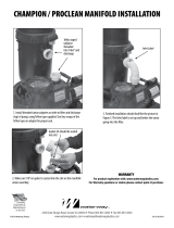
1. Hang Poly Storm Gunite Jet Body with ties through preset holes onto steel rebar.
3. Glue 2 ½" cap onto end of pipe for pressure test before guniting.
5. Cut a piece of 1" PVC pipe a couple of inches longer than the 2 ½" pipe and glue the
threaded retainer ring to it.
7. Draw a reference line on the 1" PVC pipe, flush with the back edge of the measuring tool.
8. Remove the 1" pipe assembly from the jet body assembly and realign the measuring tool with
the reference line. Make a new line at the Poly Storm Gunite Jet setback on the measuring tool.
6. Insert 1" PVC pipe assembly through the niche and up to the jet body assembly and
thread in. Slide the Gunite Pipe Measuring Tool (218-1890A) over the end of the pipe until
flush against the plaster niche.
2. Estimate needed length of 2 ½" PVC pipe by thickness of wall. Cut 2 ½" PVC pipe at least
4" longer than estimated finish length. Then glue 2 ½" PVC pipe to body.
Ties
Steel Rebar
Body (211-3060)
2" Water
Estimated Length
8" min. from back of jet body
4"
2 ½" Cap
4. While guniting, scoop out gunite around the 2 ½" PVC pipe, allowing for the plaster
niche (425-5030). Before plastering, cut the 2 ½" pipe so that the plastic niche will fit flush
with the finished wall. Glue the plaster niche onto the pipe, then cover the niche with tape
for plastering.
Gunite Wall
Chip out wall
around pipe
2 ½" PVC Pipe
SCH 40
Gunite Poly Jet Niche
(425-5030)
Retainer Ring
(219-1060)
Gunite Wall
Niche
Gunite Pipe
Measuring Tool
Reference Line
Reference Line New Line
15
6
7
8
2
3
4
810-0180.0618
©2018 Waterway Plastics
2200 East Sturgis Road, Oxnard CA 93030 • Phone 805.981.0262 • Fax 805.981.9403
www.waterwayplastics.com • [email protected]
Designed,
Engineered &
Manufactured
in the USA.

9. At the new line drawn from the setback, cut the pipe.
10. Create a 1" pipe tool with coupling attached to install the pipe assembly in the
following steps.
11. Install 4-6 wraps of Teflon tape around the threaded Retainer Ring, including 1 wrap
over the o-ring. Dry fit the pipe tool with coupling on the end of the 1" pipe assembly.
Thread the assembly into the body assembly until it is snug and the pipe tool with coupling
spins freely. Remove the pipe tool from the end of the pipe assembly.
12. Put a bead of clear silicone sealant all around the back side of the wall fitting’s flange.
Prime and cement the end of the 1” pipe and fitting socket. Slide fitting onto end of 1” pipe
until tight against the plaster niche.
Retainer Ring
(219-1060)
Retainer O-Ring
(805-0219V)
Reference line
from Step 7
New line
MAKE CUT HERE
Coupling
1" Pipe Tool
(with coupling)
1" Pipe Assembly
Retainer Ring
(219-1060)
Wrap Teon Tape
Coupling
1" Pipe Tool
(with coupling)
1" Pipe Assembly
Wall Fitting
Silicone
9
10
11
12
13. Always use at least one non-adjustable internal per spa to
prevent deadheading pump.
Wall
Adjustable
(212-8050G)
Adjustable Pulsator
(212-8120G)
Adjustable Roto
(212-8010G)
Adjustable Massage
(212-8030G)
Remove
for Non-Adjustable
(217-1090)
13
14. Align tab behind escutcheon face on jet internal with slot on wall fitting. Location of
slot and tab are shown below. Push Poly Storm internal into wall fitting until it snaps into
place. To reduce water flow, turn clockwise. To increase water flow, turn counter-clockwise
until it stops turning. To remove, continue turning counter-clockwise past stopping point.
You will hear a snap to confirm release of Poly Storm internal.
15. To winterize the jet system, remove the jet internal from the wall fitting ONLY. Install a
#10 rubber expansion plug inside of the fitting opening.
Wall
Poly Storm Jet Internal
Poly Storm Jet Internal
14
15
Tab behind poly
escutcheon face
810-0180.0618
©2018 Waterway Plastics

Always use at least one Non-Adjustable internal
per spa to prevent deadheading pump.
Large Volume
212-8040G - White
17-20 GPM
Twin Roto
212-8120G - White
10 GPM
Massage (7 Nozzle)
212-8030G - White
10 GPM
Wrench
218-1890A
Handheld Jet
210-3250
10 GPM
Directional
212-8050G - White
10 GPM
Roto
212-8010G - White
10 GPM
Power Storm II
212-8250G - White
10 GPM
Multi Massage
212-8270G - White
10 GPM
Galaxy Massage
212-8530G - White
10 GPM
Galaxy
212-8190G - White
10 GPM
To prevent personal injury, shock, or property/equipment damage, an Air Spring
Check Valve (2" 600-8160, 1 ½" 600-8140) must be installed on the blower stand
pipe in case of a water backup in the air line.
NOTE: If a blower is not being used, please direct the air intake toward the ground
using the 2" Sweep Vent Grate Assembly (400-4130) on the Air Inlet Pipe.
8.3125"
min. length
5.989"
4.290"
4.640"
1" SCH 40
PVC Pipe
(not supplied)
Slot on face of
walltting
Niche
(425-5030)
2 ½" SCH 40
PVC Pipe
(not supplied)
1 ½" Socket
Air 2" Socket
Water
Blower
Water Flow Water Flow
Air
Flow UL Listed
Check Valve
Air Intake
Sweep Vent Grate Assembly
(400-4130)
Air
Flow
Air Inlet Pipe
POLY STORM JET INTERNALS AND ACCESSORIES
810-0180.00618
©2018 Waterway Plastics
WARRANTY
For product registration visit: www.waterwayplastics.com.
For Warranty questions or claims please contact point of purchase.
/