Kohler K-475-CP Installation guide
- Category
- TV stands
- Type
- Installation guide

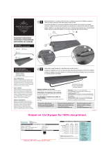
Installation Guide
Accessories
K-475, K-476, K-477,
K-478, K-480, K-482,
K-485, K-486, K-487,
K-488, K-490, K-492,
M product numbers are for Mexico (i.e. K-12345M)
Los números de productos seguidos de
M corresponden a México (Ej.
K-12345M)
Français, page “Français-1”
Español, página “Español-1”
1020823-2-D

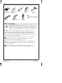
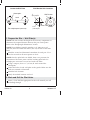
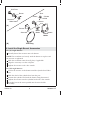
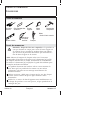
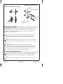
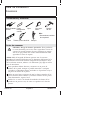
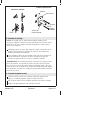
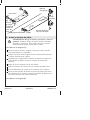
Tools and Materials
Before You Begin
DANGER: Risk of personal injury. These products are not
designed or intended for use as a grab bar or support bar. Do
not install any of these products in any area where they are
likely to be used inadvertently as a grab bar or support bar.
NOTICE: Measure the length of the bonnet included with your
accessory. Correspond the length of the bonnet with the [A] or [B]
bonnet dimension illustrated in the ″Roughing-in Information″
section. Refer to the [A] or [B] dimension throughout the installation
guide to achieve proper installation.
These products should be located and mounted to a wall stud.
While it is possible to mount them to any surface, a stud
mounted product will yield the best results.
Use a level to ensure that the center lines for the wall plates are
vertical where applicable and the post center lines are horizontal
where applicable.
Kohler Co. reserves the right to make revisions in the design of
products without notice, as specified in the Price Book.
Level
Pencil
Compass
Claw
Hammer
Assorted
Screwdrivers
Drill & 5/16" Bit
Assorted Hex
Wrenches
Measuring
Tape
• Assorted woodworking
tools
Plus:
1020823-2-D 2 Kohler Co.

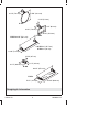
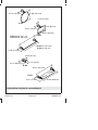
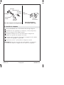
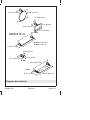
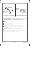
Roughing-In Information
K-480
K-482
K-478
K-477
20-1/8" (51.1 cm)
26-1/8" (66.4 cm)
K-475
K-476
K-475
K-476
18" (45.7 cm)
24" (61 cm)
6-1/8" (15.6 cm)
5-5/8" (14.3 cm)
3-1/2" (8.9 cm)
2-5/8" (6.7 cm)
3-1/8" (7.9 cm)
5-1/2" (14 cm)
1-1/4" (3.2 cm)
3-1/2" (8.9 cm)
3-1/8" (7.9 cm)
3-1/8" (7.9 cm)
26-1/2" (67.3 cm)
2-1/8" (5.4 cm)
24-3/4" (62.9 cm)
Kohler Co. 3 1020823-2-D
Page is loading ...

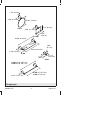
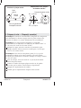
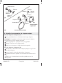
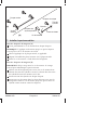
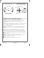
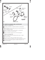
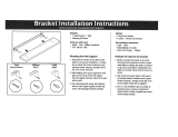
1. Prepare the Site — Wall Plate(s)
NOTE: Take into account the length of the accessory components to
determine the required distance between the post center points.
Refer to the ″Roughing-In Information″ section.
NOTE: Tissue holders generally rough-in at 8″ (20.3 cm) to 12″
(30.5 cm) above the toilet rim and 6″ (15.2 cm) in front of the toilet
bowl.
Mark the vertical and horizontal centerlines for each post. Use a
level to ensure that all center points are level.
NOTE: Once the pilot holes are drilled, there is no provision for
adjustment if the center points and the resulting pilot holes for
multiple-post accessories are not level with each other.
Using a compass, draw a 1″ (2.5 cm) D. circle around the
centerpoint.
Center the holes of each wall plate on the guides. Make sure the
holes are oriented as illustrated.
Mark the hole locations.
Verify the marked locations are level.
2. Mark and Drill the Pilot Holes
Select a 5/16″ drill bit appropriate for the wall material you will
be drilling through.
Locate the Wall Plate
Centerpoint
Level
For multiple-post layout only.
Wall Bracket Hole Locations
Wall Bracket
1"
(2.5 cm) D.
Holes
1/2"
(1.3 cm) R.
Kohler Co. 5 1020823-2-D

Mark and Drill the Pilot Holes (cont.)
Carefully drill a hole at all marked hole locations.
1020823-2-D 6 Kohler Co.

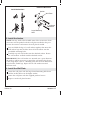
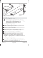
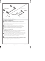
3. Install the Anchor
NOTE: You may need to disassemble some of the accessories. Some
accessories will be packed with the wall plate installed in the post.
Loosen the setscrew and remove the wall plate if needed.
Press and hold the legs of a wall anchor together, then insert the
wall anchor legs into the hole. Insert all wall anchors into the
pre-drilled mounting holes.
Carefully tap each wall anchor into the finished surface. Ensure
the wall anchors are flush with the finished surface.
IMPORTANT! If the wall anchor was inserted into a space between
the studs, it will be necessary to spread the wall anchor legs. Insert
a thin, long object (such as a finishing nail) into the wall anchor hole
to spread the anchor legs. Repeat for all wall anchors inserted
between studs.
4. Install the Wall Plate
Orient the wall plate with the large slotted mounting hole down
and the smaller hole over the higher anchor.
Secure the wall plate with the supplied panhead screws.
Repeat at each wall plate location.
Nail
Install the Anchors
Install the Wall Plate
Anchor
Wall Plate
Panhead
Screws
Large Mounting
Hole
Kohler Co. 7 1020823-2-D

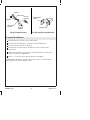
5. Install the Bonnet
Partially thread a setscrew into each bonnet.
Position the escutcheon(s), if included, onto the bonnet(s).
Slide the bonnet onto the wall plate.
Position the setscrew hole in the bonnet so the setscrew faces
downward.
Make sure the bonnet pins engage the indexing holes in the back
of the escutcheon, if applicable.
Insert a 1″ (2.5 cm) screw into the bonnet and tighten.
NOTE: When installing “Stately” accessories, make sure the bonnet
pins engage into the escutcheon holes.
Wall Plate
Anchor
Anchor
Wall Plate
Screws
Stately
Bonnet
Classic
Bonnet
For [B] Length Bonnets For [A] and [B] Length Bonnets
Escutcheon
Holes
Bonnet Pins
1020823-2-D 8 Kohler Co.

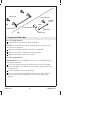
6. Install the Single Bonnet Accessories
For [A] Length Bonnets
Partially thread the setscrew into each bonnet.
NOTE: The escutcheon sits loosely until the bonnet is in place and
the setscrew is tightened.
Slide the escutcheon onto the wall plate, if applicable.
Align the accessory over the wall plate.
Tighten the setscrew with a hex wrench.
For [B] Length Bonnets
Loosen the setscrew in the bonnet until the cylinder head slides
out.
Slide the shaft of the cylinder head into the post.
Position the cylinder head with the detent facing downward.
Tighten the setscrew into the cylinder head with a hex wrench.
If needed, insert the tissue spindle into the tissue holder
assembly.
Setscrew
Shaft
Bonnet
Bonnet
Bonnet
Cylinder
Head
Tissue
Holder
Robe Hook
Setscrew
Spindle
Robe
Hook
Towel Ring
Detent
Wall Plate
[A]
[B]
Kohler Co. 9 1020823-2-D

Install the Single Bonnet Accessories (cont.)
Slide the applicable accessory into the slot in the bonnet.
Tighten the setscrew using a hex wrench.
1020823-2-D 10 Kohler Co.

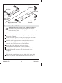
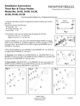
7. Install the Towel Bar
For [A] Length Bonnets
Partially thread the setscrew into each bonnet.
NOTE: The escutcheon sits loosely until the bonnet is in place and
the setscrew is tightened.
Slide the escutcheon onto the wall plate, if applicable.
Align the towel bar assembly over the wall plate.
Tighten the setscrew with a hex wrench.
For [B] Length Bonnets
IMPORTANT! Do not overtighten the setscrews. Overtightening can
damage the towel bar.
Use a hex wrench to thread a setscrew into each of the cylinder
heads and tighten. The detent on both cylinder heads should face
straight down.
Insert a cylinder head into each bonnet.
Insert a setscrew into both bonnets with a hex wrench. Tighten
the setscrews until the cylinder heads are secure against the
bonnets.
Classic Bonnet
Stately Bonnet
Setscrews
Towel Bar
Cylinder
Head
Setscrews
Shaft
Wall Plate
[A]
[B]
Kohler Co. 11 1020823-2-D

8. Install the Glass Shelf
WARNING: Risk of personal injury and product damage.
Ensure the wall plates are properly aligned and securely
anchored. If the wall plates are improperly mounted, damage
to the glass may occur.
For [A] Length Bonnets
Install the wall plates. Ensure the wall plates are properly aligned
and securely anchored.
Position the bonnet against the wall plate, keeping the slot of the
bracket assembly horizontal.
Thread the nylon-tipped setscrews counterclockwise into the
bonnet while keeping the bonnet properly aligned.
Repeat the above procedure for the second bonnet.
Wet the ends of the shelf with mild soap solution.
Carefully slide the shelf into the bracket assemblies.
Insert four nylon-tipped setscrews (provided) into the bracket
assembly. Tighten the setscrews with a hex wrench. Do not
overtighten.
For [B] Length Bonnets
Slide a bracket assembly onto each end of the shelf. Ensure both
brackets are centered on the shelf and the setscrew holes are on
the same side.
Bracket
Assembly
Nylon-Tipped
Setscrews
Cylinder Head
Setscrew
Setscrews
Nylon-Tipped
Setscrews
Stem
Wall Plate
[A]
[B]
1020823-2-D 12 Kohler Co.

Install the Glass Shelf (cont.)
Insert four nylon-tipped setscrews (provided) into the bracket
assembly. Tighten the setscrews with a hex wrench. Do not
overtighten.
Install a cylinder head onto each stem of the bracket assembly, as
shown.
Thread a setscrew into each cylinder head. Tighten the setscrew
with a hex wrench.
Measure the distance between the centers of the cylinder head
shafts.
Install the wall brackets and bonnets using the measured
dimension. The side of the bracket with the setscrew holes should
face down.
Ensure the wall plates are properly aligned and securely
anchored.
Wet the ends of the shelf with mild soap solution.
Carefully slide the shelf into the bracket assemblies. Adjust each
bracket assembly as necessary.
Tighten the nylon-tipped setscrews to secure the bracket
assemblies to the wall plates.
Kohler Co. 13 1020823-2-D
Page is loading ...
Page is loading ...
Page is loading ...
Page is loading ...
Page is loading ...
Page is loading ...
Page is loading ...
Page is loading ...
Page is loading ...
Page is loading ...
Page is loading ...
Page is loading ...
Page is loading ...
Page is loading ...
Page is loading ...
Page is loading ...
Page is loading ...
Page is loading ...
Page is loading ...
Page is loading ...
Page is loading ...
Page is loading ...
Page is loading ...
Page is loading ...
Page is loading ...
Page is loading ...
Page is loading ...
-
 1
1
-
 2
2
-
 3
3
-
 4
4
-
 5
5
-
 6
6
-
 7
7
-
 8
8
-
 9
9
-
 10
10
-
 11
11
-
 12
12
-
 13
13
-
 14
14
-
 15
15
-
 16
16
-
 17
17
-
 18
18
-
 19
19
-
 20
20
-
 21
21
-
 22
22
-
 23
23
-
 24
24
-
 25
25
-
 26
26
-
 27
27
-
 28
28
-
 29
29
-
 30
30
-
 31
31
-
 32
32
-
 33
33
-
 34
34
-
 35
35
-
 36
36
-
 37
37
-
 38
38
-
 39
39
-
 40
40


Kohler K-475-CP Installation guide
- Category
- TV stands
- Type
- Installation guide
Ask a question and I''ll find the answer in the document
Finding information in a document is now easier with AI
in other languages
- français: Kohler K-475-CP Guide d'installation
- español: Kohler K-475-CP Guía de instalación
Related papers
-
Kohler K-10481-BN Installation guide
-
Kohler K-12153-CP Installation guide
-
-
-
Kohler K-8524-CP Installation guide
-
-
-
-
-
Other documents
-
 Del Hutson Designs DHD2108nat User guide
-
Legrand Wire & Seam Clip & End Fittings Installation guide
-
 Kate and Laurel 212149 Installation guide
-
Speakman VS-153-ADA-BN Installation guide
-
Ginger USA 1139CR5/SN Installation guide
-
WaterWorks LDRH15 Installation guide
-
 Wallscapes HWRP824 Operating instructions
-
 Wallscapes VAZURE1012BK Operating instructions
-
 Newport Brass 35-28/20 Installation guide
-
Moen YB8088CH Owner's manual


