Page is loading ...

6245 State Road Telephone 215-624-4800
Philadelphia 800-344-4802
PA 19135-2996 FAX: 215-624-6966
TECHNICAL MANUAL
FOR
DOOR TYPE
DISHWASHING
MACHINE
MODELS
COMMANDER 18-3
COMMANDER 18-3C
CS-4
CS-4C

DOOR TYPE DISHMACHINES MODEL:
Commander 18-3 & CS-4
Table of Contents
Part 1 - Technical Information
* Section A, Introduction
* Catalogue Cat-sheet and Installation Drawing
* Warranty
Part 2 - Installation and Operation Instructions
* Section A, Installation Instructions
* Section B, Operation and Cleaning Instructions
Part 3 - Maintenance and Repair Procedures
* Section A, Maintenance and Repair Procedures
* Basic Service Guide
Part 4 - Electrical Schematics and Replacement Parts
* Machine Wiring Diagrams
* Control Panel Layout and Component Drawing
Part 5 - Replacement Parts
* Overall Assembly Drawing for:
* Commander 18-3, CS-4
* Commander 18-3C, CS-4C
* Drain Assembly
* Motor Assembly
* Pump, Motor & Suction Assembly
* Level Float Installation
* Final Rinse Assembly
* Steam Injectors, Steam Coils and Steam Booster Assembly's
* Electric Heater, Diode and Level float
* Electric Booster Assembly
* Self Contained Booster Assembly
rlsd: 4/91, rvsd: 11/92, 5/94
q:\wp51\manual\mnl11831.doc

COMMANDER 18-3 A CS-4
TECH MANUAL INTRODUCTION
Part I, Section A
A. INTRODUCTION
A.I Purpose
The purpose of this Tech Manual is to provide installation, operation, cleaning and
maintenance directions. A section is provided for replacement parts.
A.2 Scope
This manual contains all pertinent information to assist in the proper installation, operation,
cleaning, maintenance, and parts ordering for the model Commander 18-3 and CS-4 dishwashers.
The installation instructions are intended for qualified equipment installers. The operation and
cleaning instructions are intended for the daily users of the equipment. The maintenance and parts
sections are intended for qualified service and/or maintenance technicians. Replacement parts
may be ordered directly from our factory or from your local Insinger Authorized Service Agency. For
the name of your local Insinger Authorized Service Agency please call the Insinger Technical
Services Department, 800/344-4802. When calling for warranty information or replacement parts
please provide the model and serial number of your Insinger equipment.
A.3 Start-Up Program
Insinger offers an excellent start-up program to our commercial customers. This service is included
in the purchase price of your new Insinger dishwasher. We will provide an authorized factory
service technician for the initial start-up of your new Insinger dishwasher to ensure it is running
correctly. Please call the factory or your Insinger Sales Representative to schedule this service.
A.4 Definitions
Throughout this guide you will find the following terms: WARNING, CAUTION, & NOTE. When
used, these terms will be outlined in a box to draw attention:
WARNING indicates potential physical danger.
CAUTION indicates potential equipment damage.
NOTE indicates helpful operating hints or tips.
rlsd: 4/91, rvsd: 11/92, 5/94
q:\wp51\manual\mnl1831.doc

ltem#
100 Years of Service
Commander 18-3
AUTOMATIC SINGLE TANK
DOOR TYPE DISHWASHER
DESIGN
Automatic door type, single tank dishwasher with timed wash-
and-rinse cycle. Fully automatic operation with power on/off
button. Capacity is 65 - 20" x 20" racks per hour, or 1625 dishes
per hour. Cycle starts when doors are closed. Designed for
straight through operation. Corner model available for right
angle operation.
STANDARD EQUIPMENT
• Space saving compact design
• Door Safety Switch
• Detergent Connection Provision
• Fully Automatic Operation
• Top Mounted Control Panel
(NEMA12)
• Simplified Scrap Screen Design
• Interchangable Upper and Lower
Wash and Rinse Arms
• Standard Frame Drip Proof Motor
• Tank heat: 3 KW electric immersion
heater or steam injector
OPTIONAL ACCESSORY EQUIPMENT
? Pressure Reduction Valve and
Line Strainer
? Stainless steel steam coil tank
heat
? Gas tank heat
? Steam booster
•
Capillary Thermometer for
Wash
• In-Line Thermometer for Final
Rinse
• Vacuum Breaker
• Four Plastic 20" x 20" Racks
• (2 Plate Racks and 2 Silver
Racks)
• Manifold Cleanout Brush
• Inspection Door
•
S/S frame with S/S Legs
?
Built
-
in electric booster
? Remote electric booster
? Security package
? Totally Enclosed Motor
? Door Activated Drain
Closer
NOTES:

Note: For all rough in connections see Installation and Layout Detail Drawing.
SPECIFICATIONS
CONSTRUCTION—Hood and tank constructed of 16 gauge 18-8 type 304 S/S. Hood unit of all welded seamless
construction. S/S base frame and legs. All internal castings are non-corrosive lead free nickel alloy or bronze.
DOORS—a front inspection/cleanout door and two simultaneously opening operating doors. Operating doors have
fingertip control, balanced by externally mounted springs. (Corner model available with 2 doors at right angles.) Extra
large die formed 18-8 type 304 S/S doors ride in all S/S channels. A triple ply leading edge on the door channels made of
S/S with no plastic or nylon sleeves or liners used.
PUMP—Centrifugal type "packless" pump with a brass petcock drain. Construction includes ceramic seal and a
balanced cast impeller on a precision ground stainless steel shaft. All working parts mounted as an assembly and
removable as a unit without disturbing pump housing. One 1 HP motor, standard/frame, horizontal C-faced, drip proof,
squirrel-cage, induction run type, 60 cycle, 3400 RPM, internally cooled with ball-bearing construction.
CONTROLS—Top-mounted control cabinet, NEMA 12 rated with heat insulation provided between hood and control
cabinet, housing motor controls and overload protection, transformer, contactors and all dishwasher integral controls. All
controls safe low voltage 24 VAC.
SPRAY SYSTEM—Wash and rinse spray systems made of 18-8 type 304 S/S schedule 40 pipe threaded into cast hub
assemblies. Upper and lower spray assemblies are interchangeable and are removable without the use of tools.
Wash—2 power spinning wash arms above and 2 power spinning wash arms below each designed with 4 high pressure
action
cleansing slots. The slots are precision milled for water control producing a fan spray.
Final Rinse—2 power spinning rinse arms above and 2 power spinning rinse arms below each designed with 4 nozzle
assemblies.
Nozzle assemblies produce a cone spray reducing water consumption, maximizing heat retention.
DRAIN—Drain valve externally controlled. Overflow assembly with skimmer cap is removable without use of tools for
drain line inspection. Heater protected by low water level control.
Capacity
per hour
65 racks
1625 dishes
75-150 meals
Tank
capacity
5.6 gals.
Motor
size
1 hp (wash)
Electric usage
3 kw wash tank
13.5 kw b.i. booster 40°rise
6 kw rem. booster 40°rise
10kw rem. booster 70°rise
Steam consumption
at 20 psi min.
11 lbs./hr. tank
21 Ibs./hr. booster 40°rise
Final rinse peak
flow at 20 psi min.
2.56 gals./min.
Final rinse
consumption at 20
psi min.
58.5 gals./hr.
.90 gals./rack
Exhaust hood
requirement
100 CFM
Peak rate
drain flow
9 gals./min.
Shipping
weight
550 Ibs.
Current draw Steam/Gas Electric Electric
amps w/o Booster w/ Built-In
115/1/60 ...................11......................43.........................n/a
208/3/60 .................…5......................13.........................51
230/1/60 .................…7......................19.........................81
230/1/60 .................…4......................11.........................51
380/3/60 .................…3....................…9.........................n/a
460/3/60 .................…2...................….6.........................
24
Commander
18
-
3
Insinger's Full Line Specification Data Available in First Place.™
2M
5
-
94
—
Printed in U.S.A.

* ADD 3 KW FOR ELECTRIC HEAT, PLUS
13.5 KW FOR BUILT-IN ELECT. BOOSTER..
** 10 KW FURNISHED WHEN SPECIFIED.
^ FOR HOT WATER TO BOOSTER 140' F STANDARD / 110 F
SPECIAL.
NOTES;
1. WASH TANK IS FILLED THRU THE FINAL RINSE LINE.
2. FOR GAS HEATED MACHINE SEE DWG 18-3G.
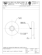
INSTALLATION CONNECTIONS
LTR
DESCRIPTION SIZE
A HOT WATER TO FINAL RINSE - 180- F 1/2 FIPS
B HOT WATER TO REMOTE ELEC.
BOOSTER
^
1/2 FIPS
C HOT WATER TO STEAM BOOSTER A 1/2 FIPS
D STEAM TO TAW 1/2 FIPS
E STEAM TO STEAM BOOSTER 1/2 FIPS
F DRAIN CONNECTION 1 1/2 FIPS
G CONDENSATE RETURN - STEAM
BOOSTER
1/2 FIPS
H CONDENSATE RETURN - COIL ONLY 3/8 FIPS
I ELECTRICAL CONNECTION - MOTORS 1 HP *
J ELECTRICAL CONNECTION-REMOTE
BOOSTER
6 KW **
K HOT WATER TO B.I. ELEC. BOOSTER ^ 1/2 FIPS

LTR DESCRIPTION SIZE
A HOT WATER TO FINAL RINSE –
180’
½ FIPS
B HOT WATER TO REMOTE
ELEC. BOOSTER ^
½ FIPS
C HOT WATER TO STEAM
BOOSTER^
½ FIPS
D STEAM TO TANK ½ FIPS
E STEAM TO BOOSTER ½ FIPS
F DRAIN CONNECTION 1 ½ FIPS
G CONDENSATE RETURN –
STEAM BOOSTER
½ FIPS
H CONDENSATRE RETURN –
COIL ONLY
3/8 FIPS
I ELECTRICAL CONNECTION –
MOTORS
1 HP*
J ELECTRICAL CONECTION –
REMOTE BOOSTER
6 KW**
K HOT WATER TO B.I. ELECT.
BOOSTER^
½ FIPS
* ADD 3KW FOR ELECTIC HEAT, PLUS 13.5
KW FOR BUILT-IN ELECT. BOOSTER.
** 10 KW FURNISHED WHEN SPECIFIED.
^ FOR HOT WATER TO BOOSTER 140’ F
STANDARD3CG./ 110’ SPECIAL.
NOTES:
1. WASH TANK IS FILLED THRU THE FINAL
RINSE LINE.
2. FOR GAS HEATED MACHINE SEE DWG.
18-3CG.

INSTALLATION CONNECTIONS
LTR
DESCRIPTION SIZE
A HOT WATER TO FINAL RINSE - I80' F 1/2 FIPS
B DRAIN CONNECTION 1 1/2 FIPS
C GAS CONNECTION 3/4 FIPS
D ELECTRICAL CONNECTION 1 HP
NOTE:
1. WASH TANK IS FILLED THRU THE FINAL
RINSE TANK.
* 2. ALLOW 2
FEET MINIMUM FROM A
VERTICAL COMBUSTIBLE WALL

INSTALLATION CONNECTIONS
LTR DESCRIPTION SIZE
A
HOT WATER TO FINAL RINSE -
180°F
1/2 FIPS
B
DRAIN CONNECTION
1 1/2 FIPS
C
GAS CONNECTION
3/4 FIPS
D
ELECTRICAL CONNECTION
1 HP
NOTES:
1. WASH TANK IS FILLED THRU THE
FINAL RINSE LINE.
* 2. ALLOW 2 FEET MINIMUM FROM A
VERTICAL COMBUSTIBLE WALL

DESIGN
Automatic door type, single tank dishwasher with timed wash-and-rinse cycle. Fully
automatic operation with power on/off button. Capacity is 65 - 20"x20" racks per
hour, or 1625 dishes per hour. Cycle starts when doors are closed. Designed for
straight through operation. Corner model available for right angle operation.
STANDARD EQUIPMENT
• Space saving compact design
• Capillary Thermometer for Wash
• Door Safety Switch
• In-Line Thermometer for Final Rinse
• Detergent Connection Provision
Vacuum Breaker
• Fully Automatic Operation
• Four Plastic 20" x 20" Racks
• Top Mounted Control Panel
(2 Plate Racks and 2 Silver Racks)
(NEMA12)
• Manifold Cleanout Brush
• Simplified Scrap Screen Design
• Inspection Door
• Interchangable Upper and
• S/S frame with S/S Legs
Lower Wash and Rinse Arms • Automatic Tank Fill
• Standard Frame Drip Proof Motor
• Low Water Protection
• Tank heat: 3 KW electric immersion
• Override Switch for De-liming
heater or steam injector
• Pressure Reduction Valve and • Built-in electric booster
Line Strainer • Remote electric booster
• Stainless steel steam coil tank heat • Security package
• Gas tank heat • Totally Enclosed Motor
• Steam booster • Door Activated Drain Closer

Note: For all rough in connections see Installation and Layout Detail Drawing.
SPECIFICATIONS
CONSTRUCTION—Hood and tank constructed of 16 gauge 18-8 type 304 S/S. Hood unit of all welded seamless construction.
S/S base frame and legs. All internal castings are non-corrosive lead free nickel alloy or bronze.
DOORS—a front inspection/cleanout door and two simultaneously opening operating doors. Operating doors have fingertip
control, balanced by externally mounted springs. (Corner model available with 2 doors at right angles.) Extra large die formed 18-8
type 304 S/S doors ride in all S/S channels. A triple ply leading edge on the door channels made of S/S with no plastic or nylon
sleeves or liners used.
PUMP—Centrifugal type "packless" pump with a brass petcock drain. Construction includes ceramic seal and a balanced cast
impeller on a precision ground stainless steel shaft. All working parts mounted as an assembly and removable as a unit without
disturbing pump housing. One 1 HP motor, standard frame, horizontal C-faced, drip proof, squirrel-cage, induction run type, 60
cycle, 3400 RPM, internally cooled with ball-bearing construction.
CONTROLS— Top-mounted control cabinet, NEMA 12 rated with heat insulation provided between hood and control cabinet,
housing motor controls and overload protection, transformer, contactors and all dishwasher integral controls. All controls safe low
voltage 24 VAC.
SPRAY SYSTEM—Wash and rinse spray systems made of 18-8 type 304 S/S schedule 40 pipe threaded into cast hub
assemblies. Upper and lower spray assemblies are interchangeable and are removable without the use of tools.
Wash—2 power spinning wash arms above and 2 power spinning wash arms below each designed with 4 high pressure action
cleansing slots. The slots are precision milled for water control producing a fan spray.
Final Rinse—2 power spinning rinse arms above and 2 power spinning rinse arms below each designed with 4 nozzle assemblies.
Nozzle assemblies produce a cone spray reducing water consumption, maximizing heat retention. The final rinse piping is
Chlorinated Poly Vinyl Chloride.
DRAIN—Drain valve externally controlled. Overflow assembly with skimmer cap is removable without use of tools for drain line
inspection. Heater protected by low water level control.
Capacity per hour
60 racks
1500 dishes
75-150 meals
Tank capacity
5.6 gals
Motor size
1 hp
Electric usage
3 kw wash tank
Steam consumption
11 lbs./hr. tank
Final rinse peak
1.1 gals./min.
Final rinse
consumption
at 20 psi min.
68 gals./hr.
1.13 gals./rack
Exhaust hood
requirement
100 CFM
Peak rate
drain flow
9 gals./min.
Shipping
weight
550 l s.
Current draw Steam/Gas Electric
amps w/o Booster
115/1/60.........................................11.................................43
208/3/60.......................................…5.................................13
230/1/60.......................................…7.................................19
230/3/60.......................................…4.................................11
380/3/60.......................................…3...............................…9
460/3/60.......................................…2...............................…6
2M 5-94 – Printed in U.S.A.

NOTES:
1. WASH TANK IS FILLED THRU THE
FINAL RINSE LINE.
2. CHEMICAL SANITIZER
INJECTOR PUMP FURNISHED.
INSTALLATION CONNECTIONS
LTR DESCRIPTION SIZE
A HOT WATER TO FINAL RINSE-140'F 1/2 FIPS
B STEAM TO TANK COIL 1/2 FIPS
C DRAIN CONNECTION 1 1/2 FIPS
D CONDENSATE RETURN - TANK COIL 3/8 FIPS
E ELECTRICAL CONNECTION 1 HP*

NOTES:
1. WASH TANK IS FILLED THRU THE
FINAL RINSE LINE.
2. CHEMICAL SANITIZER
INJECTOR PUMP FURNISHED.
INSTALLATION CONNECTIONS
LTR
DESCRIPTION SIZE
A HOT WATER TO FINAL RINSE-140°F 1/2 FIPS
B STEAM TO TANK COIL 1/2 FIPS
C DRAIN CONNECTION 1 1/2 FIPS
D CONDENSATE RETURN -TANK COIL 3/8 FIPS
E ELECTRICAL CONNECTION 1 HP*

COMMANDER 18-3 & CS-4
INSTALLATION INSTRUCTIONS
Part 2, Section A
A.I PLACEMENT
A.1.1 Carefully uncrate machine. Take caution to not damage components which may be
mounted on the top or sides of the machine.
A.1.2 Set unit in place and adjust the feet to level the machine. A .1.3 Fasten the tables to the load
and unload side of the machine. Most installations require fastening the turn-down Up of the
dish tables to the side of the machine with flathead counter-sunk screws. The table design
should provide horizontal clearance of 30" for servicing.
A.2 ELECTRICAL CONNECTIONS
A.2.1 Connect electrical lines sized for the correct voltage, current and phase of the machine.
These should agree with machine requirements Indicated on the nameplate and labels
in control panel.
A.2.2 A single-point electrical connection is provided for the pumps, control circuit, and wash
tank heater.
A.2.3 If an electrical booster is provided connect the power directly to the booster. If the Insinger
Self-Contained booster is provided the machine comes standard with a Single-Point
Connection.
CAUTION
In each case connections must be made to a circuit breaker or fused
disconnect as provided by the end-user and required by local codes. A
laminated wiring diagram is inside the control panel.
CAUTION
As with any 3 phase system, an electrician should check all motors for
proper phasing, i.e.. Pump motors must be running in direction Indicated
by arrow on housing.
A.3 MECHANICAL CONNECTIONS
A.3.1 Connect 140DEGF water lines for tank fills/booster as tagged and noted on the installation
drawings.
A.3.2 If machine is provided with steam heat connect the steam lines and steam condensate lines as
tagged and noted on installation drawings. If machine is provided with gas heat, connect the
gas lines for each tank.
A.3.3 Connect the drain line.
rlsd: 4/91, rvsd: 11/92, 5/94
q:\wp51\manual\mnll831.doc

COMMANDER 18-3 & CS-4
INSTALLATION INSTRUCTIONS
Part 2, Section A
A.3 MECHANICAL CONNECTIONS, cont'd
CAUTION
Drain lines mast be as specified on installation drawings. Drain line should be
properly vented and should have fall of not less than 1/4" to the foot of proper
flow. Some area plumbing codes require drains to flow into an open gap with an
opening twice the diameter of the pipe. Check with your local plumbing codes for
the type of drain connection required.
CAUTION
All lines should be flushed prior to use to remove debris.
CAUTION
Do not reduce the size of lines as specified in installation drawings. All
lines are sized to facilitate necessary flows, pressures, etc.
A.4 HVAC
A. 4.1 Ventilation system should be sized to provide adequate ventilation per machine specs.
Refer to spec sheet.
A.5 Chemicals
A.5.1 Upon completed installation of the dishwasher contact a local detergent/chemical supplier for
the correct chemicals for your area.
A.5.2 Electrical connection points for the detergent dispenser and rinse injector are located inside the
control panel. Refer to the wiring diagram for this machine for the proper connection points.
Dispensers may be connected on either the primary voltage side of the machine or the 2 4 VAC
control voltage side.
CAUTION
When connecting on the 24VAC control voltage side of the
transformer, total KVA must not exceed 5 OVA.
A.5.3 The detergent density probe should be located in a convenient place in the wash
tank.
rlsd: 4/91, rvsd: 11/92, 5/94
q: \wp51\inanual\mnll831.doc

COMMANDER 18-3 & CS-4
INSTALLATION INSTRUCTIONS
Part 2, Section A
A.5 Chemicals cont'd
A.5.4 A switch on the control panel labeled "Wash Cycle" is provided for de-liming the machine.
When activated, this switch will keep the machine in an indefinite wash cycle.
A.6 Tabling
A.6.1 Load and unload tables should be pitched towards the machine to return excess water into the
machine.
rlsd: 4/91, rvsd: 11/92, 5/94
q:\wp51\manual\mnll831.doc

COMMANDER 18-3 & CS-4
OPERATION & CLEANING INSTRUCTIONS
Part 2, Section B
Insinger dishmachines cure user-friendly, making then the easiest dishwashers on the market to
operate and maintain.
By following the operation procedure and general cleaning procedures your Insinger dishwasher will give
you years of trouble free service.
B.1 Operation Instructions
B.1.1 Ensure drain overflow tube is in place Close the tank drain valve.
B.1.2 Check for proper installation and cleanliness of all internal, removable components such as
suction strainers, scrap screens, and spray manifolds. B.1.3. Ensure all water, steam, and gas
lines are open. Ensure electrical circuits are on.
B.1.4 Close machine doors.
B.1.5 Move the power toggle switch to the "ON" position. The machine will fill the tank, run through a
complete wash/rinse cycle and shut-off.
B.1.6 When the tanks are full the tank heat will operate automatically. Proper tank heat temperature
is 156DEGF minimum. Proper final rinse temperature is 180DEGF minimum.
CAUTION
To ensure proper operation of the auto tank fill feature and the tank heaters, level float(s) located in each
tank MOST be cleaned daily.
B.1.7 Open doors.
B.1.8 Insert a rack of soiled dishware in machine a
nd lower doors. Machine will wash
and rinse automatically. When the rinse indicator light goes off the machine
cycle is complete.
WARNING
Do not open the doors during the wash/rinse cycle as hot water is being
sprayed. An interlock is provided to stop the wash/rinse cycle if the
doors are open but the momentum of the spinning hubs will cause hot
water to be sprayed.
rlsd: 4/91, rvsd: 11/92, 5/94
q:\wp51\manual\mn11831.doc
NOTE
Overloading racks will minimize the proper cleaning of ware.

COMMANDER 18-3 & CS-4
OPERATION & CLEANING INSTRUCTIONS
Part 2, Section B
B.1 Operation Instructions cont'd
B.1.9 Raise doors and remove rack of clean ware. For continuous operation repeat steps
B.1.9 and B.1.10.
B.1.10 Upon completion of ware cleaning move the power toggle switch to the "OFF" position.
B.1.11 Refer to the cleaning procedures for proper clean up of the dishmachine.
B.1.12 A switch on the control panel labeled "Wash Cycle" is provided for de-liming the machine.
When activated, this switch will keep the machine in an indefinite wash cycle.
B.1.13 Report any unusual occurrences to qualified service personnel.
The following cleaning procedures should be done daily, at the end of the shift.
B.2 Cleaning Procedures, Daily
B.2.1 Remove all internal removable parts including spray manifolds, scrap screens, drain overflow
tubes, suction strainers and curtains.
B.2.2 Remove the end caps from the spray manifolds and clean with the brush provided.
Flush the manifolds.
B.2.3 Flush scrap screens.
B.2.4 Clean drain overflow tube.
Note
V-cup seal on the drain overflow tube may become gummed and not allow
a proper seat of the overflow tube. This will cause the drain to leak water.
Remove any build-up on the V-cup seal. When the seal becomes worn,
replace.
B.2.5 Clean suction strainers of build-up.
Note
Improper cleaning of suction strainers will cause the pumps to
cavitate. This will cause poor washing results.
B.2.6 Clean tank level float(s).
CAUTION
Level floats must be cleaned daily. Build-up of grease and debris will
cause faulty operation of tank fill and heating system.
rlsd: 4/91, rvsd: 11/92, 5/94
q: \wp5 1\manual\mn11831 .doc

COMMANDER 18-3 & CS-4
OPERATION & CLEANING INSTRUCTIONS
Part 2, Section B
B.2 Cleaning Procedures, Daily cont'd
B.2.7 Final rinse nozzles should be cleaned of matter clogging the jet spray.
B.2.8 Doors should be left open to allow drying of interior surfaces.
rlsd: 4/91, rvsd: 11/92, 5/94
q: \wp51\manuall\mn11831.doc

DOOR TYPE DISHMACHINES
MAINTENANCE and REPAIR PROCEDURES
Part 3, Section A
Following is a basic guide for the repair and replacement of common dishwasher parts.
Refer to the Basic Service Guide for troubleshooting tips.
A.1 MAINTENANCE
A.1.1 Daily - Refer to the operation and cleaning instructions provided in this manual for daily
cleaning procedures.
A.1.2 Weekly
A.1.2.1 The entire machine should be wiped down using an industrial grade stainless steel
cleaner.
A.1.2.2 Under the supervision of your detergent supplier the machine interior must be
properly de-limed.
NOTE
The water quality in some areas requires de-liming
to be done more frequently. Contact your detergent
supplier for recommended de-liming frequency.
A.1.3 Quarterly
A.1.3.1 Remove and clean the strainer screens on water and steam lines. If the screens
cannot be cleaned, replace.
A.1.3.2 Inspect condition of solenoid valve seats and diaphragms. Replace where
necessary.
A.1.3.3 Inspect drain 0-Rings for leakage. Replace where necessary.
A.1.3.4 Check door spring tension and adjust where necessary.
A.1.3.5 Check wash and rinse hub bushing/bearing and replace where necessary.
A. 2 MAINTENANCE PROCEDURES
A.2.1 Solenoid Valve Disassembly
A.2.1.1 Disconnect power supply to machine. Turn off Water supply.
A.2.1.2 Remove cap on top of coil. Remove coil.
A.2.1.3 Remove 4 hex bolts and lift bonnet from valve body. Note positioning of spring
and plunger.
A.2.1.4 Remove main piston.
A.2.1.5 Inspect for dirt, wear or lime build-up. Clean or replace as required.
A.2.1.6 Reassemble in reverse of disassembly.
rlsd: 4/91, rvsd 5/94
q: \wp51\inanual\doorn&r.doc
/