Page is loading ...

ENGLISH
50 c - 70 c
INSTALLATION AND SERVICING MANUAL
ALKON

2
http://www.unicalag.it/prodotti/professionale-300/light-commercial-alluminio/1004/alkon-70
http://www.unicalag.it/prodotti/professionale-300/light-commercial-alluminio/1003/alkon-50

3
Installation Instructions
Technical Features
General information
Maintenance instructions
ENGLISH
4 MAINTENANCE INSTRUCTIONS ................................................................................................................................... 32
4.1 Inspection and maintenance instructions .................................................................................................................32
4.3 Adaptation to the use of other gas ..........................................................................................................................34
4.4 Operation parameters programming ........................................................................................................................35
4.5 Wiring diagram ......................................................................................................................................................... 39
4.6 Error codes ..............................................................................................................................................................41
3 INSTALLATION INSTRUCTIONS.....................................................................................................................................16
3.1 General warnings ......................................................................................................................................................16
3.2 Installation standards ................................................................................................................................................16
3.3 Preventive system verication and adjustment operations .......................................................................................16
3.4 Packaging .................................................................................................................................................................17
3.5 Positioning the boiler .................................................................................................................................................18
3.6 Flue gas exhaust pipe connection.............................................................................................................................19
3.7 Connections ..............................................................................................................................................................23
3.8 Filling the system ......................................................................................................................................................24
3.9 Electrical connections ..............................................................................................................................................25
3.10 Commissioning..........................................................................................................................................................27
3.11 Measurement of combustion eciency during installation ........................................................................................28
3.11.1 Calibration function activation ........................................................................................................................28
3.11.2 Probes positioning ..........................................................................................................................................28
3.12 Burner adjustment .....................................................................................................................................................29
3.12.1 Adaptation of the power to the heating system ..............................................................................................31
Attention: this manual contains instructions for the exclusive use of the professionally qualied installer and/or maintenance
technician in compliance with current legislation.
The user is NOT qualied to intervene on the boiler.
The manufacturer will not be held liable in case of damage to persons, animals or objects resulting from failure to comply with
the instructions contained in the manuals supplied with the boiler.
2 TECHNICAL FEATURES AND DIMENSIONS ................................................................................................................10
2.1 Technical features ....................................................................................................................................................10
2.2 Main components view and dimensions ..................................................................................................................10
2.3 Dimension ................................................................................................................................................................10
2.4 Available ow rate / pressure diagram .....................................................................................................................12
2.5 Operation data .........................................................................................................................................................13
2.5.1 Data according to the ErP directive ...............................................................................................................14
1 IGENERAL INFORMATION ...............................................................................................................................................4
1.1 General warnings .......................................................................................................................................................4
1.2 Symbols used in the manual ......................................................................................................................................5
1.3 Appropriate use of appliance .....................................................................................................................................5
1.4 IInformation for system manager ...............................................................................................................................5
1.5 Safety warnings .........................................................................................................................................................6
1.6 Technical data plate ..................................................................................................................................................7
1.7 Water treatment .........................................................................................................................................................8
1.8 Boiler antifreeze protection ........................................................................................................................................9

4
1
GENERAL INFORMATION
Any repairs must be performed solely by personnel authorised
by Unical AG S.p.A., using original spare parts only. Failure to
comply with the above can compromise the safety of the appli-
ance and void the warranty.
To guarantee appliance eciency and its correct operation,
yearly maintenance must be performed by qualied personnel.
Should you decide not to use the appliance, parts entailing
potential sources of hazard must be made safe.
Before commissioning an appliance that has not been used,
wash the domestic hot water production system, making the
water ow until it has been fully replaced.
Should the appliance be sold or transferred to a new owner or
if you move and leave the appliance, always make sure that the
instruction booklet accompanies it in order to be consulted by
the new owner and/or installer.
Only original accessories must be used for all appliances with
optionals or kits (including electric).
This appliance is intended solely for the use for which it was
expressly designed.
Any other use is to be considered improper and therefore dan-
gerous (*).
1.1 - GENERAL WARNINGS
The instruction booklet is an integral and essential part of the
product and must be kept by the user.
Read the warnings contained in this instruction booklet carefully
as they provide important guidelines regarding installation, use
and maintenance safety.
Keep the booklet with care for further consultation.
Installation and maintenance must be performed in compliance
with the standards in force according to the instructions of the
manufacturer, up to standard and by personnel qualied and
certied in compliance with law.
Systems for the production of domestic hot water MUST be
constructed entirely with compliant materials.
By professionally qualied personnel we mean: personnel with
specic technical skill in the eld of heating system components
for civil use, domestic hot water production and maintenance.
Personnel must have the qualications provided for by current
legislation.
Incorrect installation or improper maintenance can cause dam-
age to persons, animals or objects for which the manufacturer
is not responsible.
Before performing any cleaning or maintenance, disconnect the
appliance from the energy mains by acting on the switch of the
system and/or through the specic cut-o devices.
Do not obstruct the terminals of the intake/exhaust ducts.
In case of failure and/or malfunctioning of the appliance, switch
it o and do not try to repair it or intervene on it directly. Contact
only personnel qualied in compliance with law.

5
1.2 - SYMBOLS USED IN THE MANUAL
Pay special attention when reading this manual to the parts marked by the symbols:
NOTE!
Tips
for the user
ATTENTION!
Possible dangerous
situation for the product
and the environment
DANGER!
Serious danger
to safety
and health
1.3 - APPROPRIATE USE OF APPLIANCE
The heat generator has been built according to the current level of engineering and acknowledged technical
safety rules.
Nonetheless, if improperly used, dangers could arise for the safety and life of the user and other persons
or damage to the equipment or other objects.
The appliance is designed to work in heating systems, with hot water circulation, for the production of
domestic hot water.
Any other use must be considered improper.
For any damage resulting from improper use, UNICAL AG S.p.A. assumes no responsibility.
Use according to the intended purposes also includes strict compliance with the instructions in this manual.
The user must be instructed concerning the use and operation of his heating system, in particular:
• Deliver these instructions to the user, as well as other documents concerning the appliance inserted in the envelope
inside the packaging. The user must keep this documentation safe for future consultation.
• Inform the user about the importance of the air vents and the ue gas exhaust system, highlighting their essential
features and the absolute prohibition of modifying them.
• Inform the user concerning controlling the system's water pressure as well as operations to restore it.
• Inform the user concerning correct temperature control, control units/thermostats and radiators for saving energy.
• Please note that, in compliance with the standards in force, the inspection and maintenance of the appliance must
be carried out in compliance with the regulations and frequency indicated by the manufacturer.
• Should the appliance be sold or transferred to a new owner or if you move and leave the appliance, always make
sure that the instruction manual accompanies it in order to be consulted by the new owner and/or installer.
The manufacturer will not be held liable in the event of damage to persons, animals or objects resulting from
failure to comply with the instructions contained in this manual.
1.4 - INFORMATION FOR THE SYSTEM MANAGER
NOTE!
For further details
refer to the Technical Information:
http://www.unicalag.it/prodotti/
professionale-300/light-commercial-
alluminio/1626/kon-100
OBLIGATION!
wear gloves
protective
DANGER!
Danger of burns!

6
1.5 - SAFETY WARNINGS
ATTENTION!
The boiler cannot be used by children.
The boiler can be used by adults and only after having carefully read the user’s manual
Children should be supervised to ensure that they do not play or tamper with the device.
ATTENTION!
The appliance must be installed, adjusted and maintained by professionally qualied personnel, in compliance with
the standards and provisions in force. Incorrect installation can cause damage to persons, animals and objects for
which the manufacturer cannot be held responsible.
DANGER!
NEVER attempt performing maintenance or repairs on the boiler on your own initiative.
Any work must be done by professionally qualied personnel. We recommend stipulating a maintenance contract.
Insucient or irregular maintenance can jeopardise the operating safety of the appliance and cause damage to
persons, animals and objects for which the manufacturer cannot be held responsible.
Changes to the parts connected to the boiler (once the boiler installation is complete)
Do not modify the following parts:
- the boiler
- the gas, air, water and electricity supply lines
- the ue gas pipe, the safety valve and the exhaust pipe
- the construction parts which aect the operating safety of the appliance.
Attention!
To tighten or loosen the screwed ttings, use only appropriate xed spanners.
Incompliant use and/or inappropriate tools can cause damage (e.g. water or gas leakage).
ATTENTION!
Indications for propane gas-red appliances
Make sure that the gas tank has been deaerated before installing the appliance.
For state-of-the-art tank venting, contact the LPG supplier or person qualied in compliance with the law requirement.
If the tank has not been professionally deaerated, ignition problems could arise.
In that case, contact the supplier of the LPG tank.
Smell of gas
Should a smell of gas be perceived, follow these safety guidelines:
- do not turn electric switches on or o
- do not smoke
- do not use the telephone
- close the gas shut-o valve
- air out the area where the gas leakage has occurred
- inform the gas supplier or a company specialised in installation and maintenance of heating systems.
Explosive and easily ammable substances
Do not use or store explosive or easily ammable materials (e.g. petrol, paints, paper) in the room where the ap-
pliance is installed.
ATTENZIONE!
DANGER!
Do not use the appliance as a supporting base for objects.
In particular, do not place receptacles containing liquids (Bottles, Glasses, Jars or Detergents) on top of the appliance.
If the appliance is installed inside a housing, do not insert or rest other objects inside this housing.

7
General information
ENGLISH
1.6 - TECHNICAL DATA PLATE
KEY:
1 = CE monitoring body
2 = Type of boiler
3 = Boiler model
4 = Number of stars (directive 92/42 EEC)
5 = (S.N°) Serial Number
6 = P.I.N.ProductIdenticationNumber
7 = Typesofapproveduegasexhaustcongurations
8 = (NOx)NOxClass
A = Heatingcircuitcharacteristics
9 = (Pn) Effective nominal output
10 = (Pcond) Effective output in condensation
11 = (Qn)Maximumheatoutput
12 = (AdjustedQn)Adjustedforratedheatoutput
13 = (PMS)Max.heatingoperatingpressure
14 = (Tmax)Max.heatingtemperature
B = Domestichotwatercircuitcharacteristics
15= (Qnw)Ratedheatoutputindomestichotwaterfunction(ifdifferentto
Qn)
16= (D)SpecicD.H.W.owrateaccordingtoEN625-EN13203-1
17= (Rfactor)No.oftapsaccordingtothedeclaredamountofwater(EN
13203-1)
18 = (Ffactor)No.ofstarsaccordingtothedeclaredqualityofthewater
(EN13203-1)
19 = (PMW)Max.domestichotwateroperatingpressure
20 = (Tmax)Max.domestichotwatertemperature
C = Eletricalcharacteristics
21= Electricalpowersupply
22 = Consumption
23 = Protection rating
D = Countries of destination
24 = Direct and indirect countries of destination
25 = Gas category
26 = Supply pressure
E = Factory settings
27 = Adjusted for gas type X
28 = Space for national brands
G = ErP
29 = Seasonalspaceheatingenergyefciency
30 =EnergyefciencyinDHWproductionmode
/
The CE marking
certies the compliance of the equipment with the essential
safety requirements dened in the directives and applicable
European regulations and that its functioning satisfy applicable
technical standards.
The CE marking is axed to each piece of equipment with an
appropriate label.
The CE declaration of conformity issued in accordance with
international standards by the manufacturer, is placed in docu-
mentation envelope supplied with the product.

8
1.7 - WATER TREATMENT
The treatment of the supply water allows to
prevent inconveniences and maintain the
functionality and eciency of the generator
over time.
The ideal water pH in heating systems must
be within:
To minimise corrosion, it is crucial to use
a corrosion inhibitor; in order for it to work
properly, the metal surfaces must be clean.
(see system protection ACCESSORIES sect.
in domestic price list)
ATTENTION (*) see general warnings 1.1
The heating only models are NOT suitable for
the production of water for human consumption according
to Ministerial Decree D.M. 174/2004.
ATTENTION!
ANY DAMAGE TO THE BOILER CAUSED BY
THE FORMATION OF FOULING OR BY COR-
ROSIVE WATER WILL NOT BE COVERED BY
THE WARRANTY.
VALUE MIN MAX
PH 6,5 8
Hardness [°fr] 9 15
NOTE!
For more information
See Technical Info
from site indicated at pag. 2

9
Technical Features
ENGLISH
1.8 - BOILER ANTIFREEZE PROTECTION
ANTIFROST PROTECTION
Press ‘‘BLUE’’ button, up to led M OFF.
This protection can intervene only if the
electricity and gas supplies are connected.
If one of the two is not available and upon reset
11 (SR) a temperature between 2 ÷ 5°C is
detected, the appliance will behave as described
in tab. pos 2.
The heating system can be protected eectively
from frost by using antifreeze products with
inhibitor for heating systems (specific for
multidmetal)
Do not use car engine antifreeze products as
they could damage the water gaskets.
P
O
S
ANTIFREEZE FUNCTION
Power supplies 11 - SR (*)
Status
antifreeze function
Actions
Electric Gas
1 ON ON < 7 °C ON - Burner and Pump ON until T > 15°C
2
ON OFF
< 5 ÷ 5 °C ON
FAULT SIGNAL CODE Fr (E16)
(with Electrical power supply ON)
(see par. 4.6 - ERROR CODES).
Ignition inhibited.
OFF ON OFF Ignition inhibited.
OFF OFF OFF Ignition inhibited.
(*) Flow sensor

10
ALKON 50 c
ALKON 70 c
2
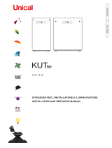
2.2 -
VIEW WITH THE INDICATION OF THE MAIN COMPONENTS
TECHNICAL FEATURES AND DIMENSIONS
2.1 - TECHNICAL FEATURES
NOTE!
Further details in the section
‘‘Technical Information’’ on the boiler
page of the www.unicalag.it website
20
22
13
11
3
35
27
28
25
18
24
32
26
R
M
G
Scond
5
42
44
43
10
KEY
N°
C.E.
S.E. Descrizione
3 VG Gas valve
5 Burner
10 HL TL Safety thermostat
11 Hb SR Heating temperature sensor (1) (2)
12 Ht P Pump (optional on alkon 50)
13 Lp DK Water deciency pressure switch
18 FL
FH
VM Fan
20 Safety valve
22 rb SRR Return temperature sensor
24 Aluminium Heat Exchanger/Ca-
pacitor

11
Technical Features
ENGLISH
20
22
13
11
3
35
27
28
25
18
24
32
26
R
M
G
Scond
12
5
42
44
43
10
ALKON 70 c
25 Vent valve
26 Condensation drain trap
27
E. RIL.
Detection electrode
28
E. ACC.
Ignition electrode
32 Outlet ue inspection
35 Ignition Trasformer
42 PFmax Flue gas pressure max
43 SL Level sensor (Only body 1)
44 PFmin Flue gas pressure min
ALKON 50 c 70 c
C Domestic hot
water outlet
(only with ACS kit)
G Gas inlet G ¾’’ G ¾’’
F Cold water inlet
(only with ACS kit)
M Heating system
ow
G 1’’ G1 ¼’’
R Heating system
return
G 1’’ G1 ¼’’
Scond
Condensation drain
A
Air Suction Ø 80
S
Exhaust Smoke Ø 80
C.E. = ERROR CODES see par. 4.6
S.E. =WIRING DIAGRAM
KEY see par. 4.5

12
(*) The parts shown in gray are relative to the ACS kit.
2.3 - DIMENSIONS
Front view
View from below
View from above
Side view

13
Technical Features
ENGLISH
If the pump are determined by the installer or
designer must be sized according to the data of
the boiler and system.
It is recommended to choose a pump with
the rate and delivery head at about 2/3 of
its characteristic heating curve.
The Dt between supply and return boiler must
never be less than 15 ° K.
A) Head gain available net losses of boiler (for boilers with pump
supplied by Unical)
B) Head losses between flow and return
(For boilers supplied without pump)
The table provides an indication the flow the pump in function of the Dt of the primary circuit.
ALKON 34,8
(ALKON 50 c Reg.34,8
kW)
ALKON 50 c ALKON 70 c
Power supply in kW 35,4 49,3 68,5
Max ow rate demanded l/h (Dt 15 K) 2030 2826 3927
Nominal ow rate request (Dt 20 K) 1522 2120 2946
residual pressure head
ALKON 70 (1)
ALKON 50 (2) (1)
PRESSURE
LOSSES
ALKON 50
Q: water ow rate (l/h)
Pressure losses (m/H
2
O)
2.4 - DIAGRAM OF FLOW RATE/PRESSURE AVAILABLE FOR INSTALLATION
NOTE:
The use of a mixing header tted between the
boiler circuit and the system circuit is always advi-
sable. It becomes INDISPENSABLE if the system
requires ow rates superior to the
maximum permitted boiler ow rates, which is to
say lower than 15K.
(1) VALUES REFER TO THE MAX SPEED
(2) ONLY IF EQUIPPED WITH OPTIONAL PUMP

14
ALKON 50 c (reg. 34,8) ALKON 50 c ALKON 70 c
Appliance category II
2H3P
II
2H3P
II
2H3P
Modulation Ratio 1 : 3,6 1 : 5 1 : 7
Nominal Heat Input on P.C.I. Qn kW 34,8 48,5 67,5
Minimum Heat Input on P.C.I. Qmin kW 9,6 9,6 9,6
Nominal Output (Tr 60 / Tm 80 °C) Pn kW 33,9 47,2 65,7
Minimum Output (Tr 60 / Tm 80 °C) Pn min kW 9,1 9,1 9,1
Nominal Output (Tr 30 / Tm 50 °C) Pcond kW 35,4 49,4 68,7
Minimum Output (Tr 30 / Tm 50 °C) Pcond min kW 10,3 10,04 10,33
Eciency at max. output (Tr 60 / Tm 80°C) % 97,29 97,29 97,29
Eciency at min. output (Tr 60 / Tm 80°C) % 94,8 94,9 94,9
Eciency at max. output (Tr 30 / Tm 50°C)) % 101,62 101,82 101,72
Eciency at min. output (Tr 30 / Tm 50°C) % 104,3 104,55 107,58
Rendimento al 30% del carico (Tr 30°C) % 107,33 107,33 107,33
Combustion eciency with nominal load % 97,80 97,82 97,38
Combustion eciency with minimum load % 98,42 98,51 98,34
Heat loss at casing with burner in operation (Qmin) % 3,62 3,60 3,44
Heat loss at casing with burner in operation (Qn) % 0,51 0,52 0,09
Flue gas temperature tf-ta (min)(*) °C 33 30,6 34
Flue gas temperature tf-ta (max)(*) °C 43,6 43,6 51,3
Maximum allowable temperature °C 100 100 100
Maximum operating temperature °C 85 85 85
Flue gas mass ow rate (min) kg/h 15,9 15,9 15,9
Flue gas mass ow rate (max) kg/h 57,4 80,0 111,4
Excess λ air % 26,84 25,53 28,17
Flue losses with burner in operation (min) % 1,58 1,49 1,66
Flue losses with burner in operation (max) % 2,20 2,18 2,62
Minimum heating circuit pressure bar 0,5 0,5 0,5
Maximum heating circuit pressure bar 6 6 6
Water content l 3,9 3,9 3,9
Gas Consumption Natural (20 mbar) gas G 20 a Qn m
3
/h 3,68 5,13 7,14
Gas Consumption Natural gas (20 mbar) G 20 a Qmin m
3
/h 1,02 1,02 1,02
Gas Consumption G25 (supply pressure 25 mbar) Qn m
3
/h 4,28 5,96 8,30
Gas Consumption G25 (supply pressure 25 mbar) Qmin m
3
/h 1,18 1,18 1,18
Gas Consumption G31 (supply pressure 37/50 mbar) Qn kg/h 2,70 3,76 5,24
Gas Consumption G31 (supply pressure 37/50 mbar) Qmin kg/h 0,75 0,75 0,75
Max. available pressure at the chimney base Pa 40 40 40
Condensate production max kg/h 5,6 7,8 10,87
Emissioni
CO at Minimum Heat Input with 0% of O2 mg/kWh 71,3 71,3 82
NOx at Nominal Heat Input with 0% of O2 mg/kWh 48 56 59
NOx Class 6 6 6
Electrical Data
Voltage/Frequency electric power supply V/Hz 230/50 230/50 230/50
Fuse on main supply A (R) 6 6 6
Insulation degree IP X4D X4D X4D
Room Temperature = 20°C
(*) Temperatures detected with the unit in operation (Tr 60 / Tm 80°C)
CO
2
(min/max) See table INJECTORS PRESSURES
Seasonal space heating energy
2009/125 CEE (<=400Kw)
η
s
- see ErP table
Stand-by heat loss ∆T 30°C - Pstb - see ErP table
Consumption in stand-by - Psb - see ErP table
2.5 - OPERATING DATA ACCORDING TO UNI 10348 and GENERAL FEATURES
For the adjustment data: NOZZLES - PRESSURE - DIAGRAMS - FLOW RATES - CONSUMPTION refer to the paragraph ADAP-
TATION TO OTHER TYPES OF GAS.

15
Technical Features
ENGLISH
2.5.1 - DATA ACCORDING TO ErP DIRECTIVE
ALKON 50 c
(reg. 34,8)
ALKON 50 c ALKON 70 c
Description Symbol Unità
Nominal Heat Output Pnominale kW 47 47 66
Seasonal space heating energy
eciency
ƞ
s % 93 93 93
Seasonal eciency class in
heating mode
A A A
For CH only and combination boilers: useful heat output
Useful Heat Output in high-tempera-
ture regime
(Tr 60 °C / Tm 80 °C)
P
4 kW 47,2 47,2 65,7
Useful eciency at nom. heat output
in high-temperature regime
(Tr 60 °C / Tm 80 °C
ƞ
4 % 87,7 87,7 87,7
Useful heat output at 30% of nom.
heat output in low-temperature
regime (Tr 30 °C)
P
1 kW 15,7 15,7 21,9
Useful eciency at 30% of nom. heat
output in low-temperature regime
(Tr 30 °C)
ƞ
1 % 97,1 97,1 97,3
Range-rated boiler: YES / NO NO NO NO
Auxiliary electricity consumption
At full load elmax kW 0,203 0,203 0,267
At part load elmin kW 0,162 0,162 0,172
In stand-by mode P
SB kW 0,005 0,005 0,005
Altri elementi
Dispersione termica in stand-by P
stb kW 0,151 0,151 0,151
Emissioni di ossidi di azoto rif. PCI (PCS) NOx
Mg/kWh
45 (41) 45 (41) 46 (42)
Consumo di elettricità annuale Q
HE GJ 60 92 120
For CH & DHW production boilers
Declarerd load prole - - -
Energy eciency in DHW production
mode
ƞ
wh % - - -
Daily electricity consumption Qelec kWh - - -
Daily fuel consumptionl Qfuel kWh - - -
Inside sound power level Lwa dB (A) 60 60 63
Annual electricity consumption AEC kWh - - -
Annual fuel consumption AFC GJ - - -
Seasonal eciency class
in DHW production mode
- - -

16
3
INSTALLATION INSTRUCTIONS
ATTENTION!
T
his boiler is intended solely for the use for
which it was expressly designed. Any other
use is to be considered improper and there-
fore dangerous.
This boiler heats water at a temperature
lower than the atmospheric pressure boiling
temperature.
Before connecting the boiler, have professionally
qualied personnel:
a) Thoroughly wash all the piping of the sys-
tem to remove any residues or impurities
which could jeopardise proper operation
of the boiler, even from a hygienic point
of view.
b) Check that boiler is set up to oper-
ate with the available type of fuel.
This can be seen written on the package and
on the technical feature plate;
c) Check that the chimney/ue has an appropri-
ate draught, without any bottlenecks, and that
no exhausts from other appliances are insert-
ed, unless the ue has been implemented to
accommodate several utilities according to
specic standards and regulations in force.
Only after this check can the tting between
the boiler and chimney/ue be mounted;
ATTENTION!
If there is dust and/or if there are aggressive/
corrosive vapours present in the installation
room, the appliance must be protected
suitably and must be able to operate
independently from the air in the room.
ATTENTION!
Only mount the appliance on a closed wall, made
of non-ammable material, at, vertical so that the
minimum distances required for installation and
maintenance can be observed.
The boiler must be connected to a central heating
system and/or domestic hot water supply network
compatible with its eciency and output.
3.1 - GENERAL WARNINGS
3.2 - INSTALLATION STANDARDS
t must be installed by a professionally qualied technician, who
shall take the responsibility of observing all local and/or
national laws published in the ocial journal, as well as
the applicable technical standards.
3.3 - PREVENTIVE VERIFICATION AND
VERIFICATION AND ADJUSTMENT
OPERATIONS
NOTE!
For further details relating to the standards,
rules and regulations for safe installation of
the thermal unit, refer to the section “Tech-
nical Information” on the boiler page of the
www.unicalag.it website
NOTE!
Further details in the section
‘‘Technical Information’’ on the boiler page of
the www.unicalag.it website
NOTE!
Further details in the section
‘‘Technical Information’’ on the boiler page
of the www.unicalag.it website

17
Technical Features
ENGLISH
As well as the appliance, the packaging contains:
A DOCUMENTATION ENVELOPE
- User operating instructions booklet
- Instruction booklet for the installer and
maintenance engineer
- 2 Spare parts form
- Certicate of conformity
- Gas conversion label
C - 3 rawlplugs for boiler attachment
E - Boiler support bracket
F - Condensate evacuation siphon
G - Aluminum pipe Ø 80 mm for smoke evacuation
(located inside the boiler)
ALKON 50 c
P
depth
L
width
(mm)
H
heigh
(mm)
Net
Weight
(kg)
Gross
Weight
(kg)
370 715 1025 50 55
ALKON 70 c
P
depth
L
width
(mm)
H
heigh
(mm)
Net
Weight
(kg)
Gross
Weight
(kg)
370 715 1025 58,4 64
3.4 - PACKAGING
The boiler ALKON 50 / 70 c is supplied completely assembled
in a sturdy cardboard box.
After having removed the appliance from the
packaging, make sure that the supply is complete
and undamaged.
The packaging elements (cardboard box, straps,
plastic bags, etc.) must be kept out of the reach
of children as they are potential sources of
danger.
Unical AG S.p.A. will not be held liable for damage
to persons, animals or objects due to failure to
comply with the instruction above.
CAUTION
The boiler could be damaged if not properly
fixed.
- Only transport the boiler using appropriate
transport equipment
- Follow the transport instructions on the
packaging.
OBLIGATION!
wear protective gloves

18
Particular importance should be given to local regulations and
laws in terms of boiler room and especially the minimum distance
that must be kept clear around the boiler.
The installation must conform to the requirements contained in
the most recent regulations and laws in terms of boiler room,
installations of heating and production of hot water, ventilation,
chimneys suitable to discharge the products of combustion of
condensing boilers, and everything else applicable.
When choosing the place of the installation of the appliance,
follow the safety instructions below:
- Place the appliance in rooms protected from frost.
- Avoid installation in rooms with a corrosive or very dusty
atmosphere.
- The appliance must only be installed on a vertical and solid
wall which can support its weight.
- The wall must not be made of ammable material.
Solo con kit ACS
C CALDA
F FREDDA
Observe the minimum distances of encumbrance
in order to perform the operations of normal
maintenance and cleaning.
3.5 - POSITIONING IN
BOILER ROOM

19
ENGLISH
Installation Instructions
3.6 - FLUE GAS EXHAUST PIPE CONNECTION
FOR BOILERS WITH FORCED DRAUGHT
To connect the ue gas exhaust pipe, local and na-
tional standards must be observed
In the event the boiler is replaced, ALWAYS re-
place the ue gas pipe as well.
The boiler is type approved for the exhaust congu-
rations listed below:
C13x C13
% Slope towards inlet = 3%
TOTAL LENGTH (LA intake + L Exhaust)
COAXIAL Ø60/100 DOUBLE Ø80
FROM [m] TO [m] FROM [m] TO [m]
NA NA 1 + 1
40
(20A+20S)
COAXIAL Ø80/125 DOUBLE Ø60
FROM [m] TO [m] FROM [m] TO [m]
1 5 NA NA
Distance between air
inlet pipe and ue gas
exhaust pipe: min 250
mm - max 500
Horizontal exhaust and intake terminals directed
outside via coaxial or double pipes..
C33x C33
TOTAL LENGTH (LA intake + L Exhaust)
COAXIAL Ø60/100 DOUBLE Ø80
FROM [m] TO [m] FROM [m] TO [m]
NA NA 0,5 + 0,5
40
(20A+20S)
COAXIAL Ø80/125 DOUBLE Ø60
FROM [m] TO [m] FROM [m] TO [m]
1 7 NA NA
ertical exhaust and intake terminals directed out-
side via coaxial or double pipes.
C53x C53
C53
NOT ALLOWED C53
TOTAL LENGTH (LA intake + L Exhaust)
DOUBLE Ø80 DOUBLE Ø60
FROM [m] TO [m] FROM [m] TOA [m]
1 + 1
40
(max 30 S)
NA NA
Separate combustion air intake and combustion
products evacuation pipes.
These pipes can discharge into areas with dierent
pressure.
C43x C43
Collective chimney ue system, consisting of two
pipes, one for combustion air intake and the other
one for combustion products evacuation, coaxial
or double.

20
CAUTION
LT total length is a reference value
for the dimensioning of the ducts of A
(intake) and S (Exhaust). Subtracting
the values of LT reported, at values of
bends* / terminals* / extensions* you
get the value:
if > 0 = OK - POSSIBLE conguration
if < 0 = NO - WRONG conguration
(*) Values in the MT018 available on the website.
B23P
TOTAL LENGTH (LS)
DOUBLE Ø80
FROM [m] TO [m]
1 30
Connection to a combustion products evacuation
pipe outside the room; the combustion air is tak-
en directly from the room where the appliance is
installed.
C83x C83
Collegamento ad un terminale per il prelievo dell’aria combu-
rente e scarico fumi mediante camino individuale o collettivo.
C93x C93
Air / ue gas through concentric pipes in the boiler
room and single pipes in the chimney (combustion
air with counterlow in the chimney)
C63x C63
Boiler intended for connection to a combustion air
intake and combustion products evacuation system,
approved and sold separately
ATTENTION:
The ue must comply with standards
in force.
ATTENTION:
For the type of connection B23P the
room follows the same installation rules
for boilers with natural draught.
Please note: These values relate to exhausts/
made by means of rigid pipes and smooth
original UNICAL.
/