Page is loading ...

Water Filtration System
Model:
Instruction Manual
Read and save these instructions
Osmosis
Reverse
WD-G3P600
service@waterdropfilter.com1-888-352-3558 (U.S.)
Contact Us


Thanks for your purchase from Waterdrop. We value your patronage and appreciate your confidence
in us. Counting you among our customers is something for which we are especially grateful. Please let
us know if we can do anything else to help.
This device complies with part 15 of the FCC Rules. Operation is subject to the following two conditions: (1) This device may not cause
harmful interference, and (2) this device must accept any interference received, including interference that may cause undesired
operation. Any Changes or modifications not expressly approved by the party responsible for compliance could void the user's
authority to operate the equipment.
Warning:
- This appliance can be used by children aged from 8 years and above and persons with reduced physical, sensory or mental capabilities
or lack of experience and knowledge if they have been given supervision or instruction concerning use of the appliance in a safe way
and understand the hazards involved.
- Children shall not play with the appliance.
- Cleaning and user maintenance shall not be made by children without supervision.
- The appliance is only to be used with the unit provided.
- If the supply cord is damaged, it must be replaced by the manufacturer or its service agent or a similarly qualified person in order to
avoid a hazard.
Disposal
Dispose of the packaging material in an environmentally friendly manner so that it can be recycled.
The device is governed by the European Directive 2012/19/EU on waste electrical and electronic equipment (WEEE). Do not
dispose of the device as normal domestic waste, but rather in an environmentally friendly manner via an officially appro ste
disposal company.

Contents
Step 1: Install the Feed Water Adapter...................................................................................................................................5
Step 2: Install the RO Faucet.........................................................................................................................................................6
Step 3: Install the Drain Saddle ...................................................................................................................................................6
Step 4: Position the RO System Housing..............................................................................................................................7
Step 5: Connect Tubing................................................................................................................................................................... 7
Step 6: Connect Power Cord........................................................................................................................................................9
Step 7: Install the Filters...................................................................................................................................................................9
Step 8: Start up the System.........................................................................................................................................................10
Installation Instructions
Before Installation.............................................................................................................................. 1
Parts List............................................................................................................................................... 2
Product Introduction ......................................................................................................................... 3
Installation Tips................................................................................................................................... 4
Installation Steps................................................................................................................................ 5
System Maintenance........................................................................................................................16
Troubleshooting ...............................................................................................................................16
Limited Product Warranty ..............................................................................................................18
Section 1: TDS Display................................................................................................................................................................... 11
Section 2: Filter Life Reminder.................................................................................................................................................. 12
Section 3: Filter Replacement Guide ................................................................................................................................... 13
Section 4: Automatic Flushing................................................................................................................................................. 14
Section 5: Malfunction Display................................................................................................................................................ 15
Owner's Manual
Display and Operation.....................................................................................................................11

1
Inspect the Package
Open the box and take out the system housing, all the components and connection fittings. Inspect them
according to the parts list to ensure nothing is left out or damaged during shipping. If there are any parts
cracked or broken, please do no proceed with the installation and contact Waterdrop customer service by
hotline +1-888-352-3558 (PST) or by email: service@waterdropfilter.com. Identify and get familiar with all
components for quick installation.
Specifications
To achieve the optimal performance, it is highly recommended to use the system within the operational
parameters.
NOTE:
• The Daily Production Rate is measured under 30 PSI dynamic feed water pressure and 77 °F water
temperature.
• If you are using well water as the source, please ensure that the feed water has been through a pre-filtration
system.
Before Installation
Installation Instructions
Required Tools
• Variable speed drill
• Utility knife or scissors
• Drill bit: 1/4" (for drainpipe), 1" (for faucet hole)
• Adjustable wrench, pliers
• Flashlight
• Towel
• Screwdriver
Model
RO System Size (L*W*H)
Feed Water Pressure
Feed Water Temperature
Feed Water Requirement
Max Daily Production Rate
Power Specification
Rated Frequency
WD-G3P600
18.12” *5.67”* 17.72”
14.5-87 PSI/0.1-0.6 MPa
41-100 °F / 5-38 °C
Municipal Tap Water
400 GPD / 600 GPD
Input 110-240V AC
50 / 60 HZ

Parts List
System Housing
X1 Set
Drain Saddle 1/4"
X1 Set
Red 1/4" PE Tubing
X60"
Power Adapter
X1 Set
Feed Water
Adapter 3/8"-1/2”
X1 Set
White 3/8"
PE Tubing
X60"
White 1/4"
PE Tubing
X60"
Lock Clip
X5
Teflon Tape
PreinstalledPreinstalled
2
Smart Digital
RO Faucet x1
WD-G3-CB
X1
WD-G3-CF
X1
WD-G3P600-RO
X1

F N, From “POWER” Port to Power Socket
O G, From Faucet Power Cord to "FAUCET' Connector
L I, From Faucet to "FILTERED" Water Port
M J, From Drain Saddle to “WASTE” Water Port
K H, From Feed Water Adapter to “INPUT” Water Port
Input Water Tubing
3/8’’PE Tube
Power Adapter
Waste Water
Tubing 1/4’’PE Tube
Drain Pipe
Filtered Water
Tubing 1/4’’ PE Tube
3
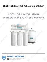
Product Introduction
T
he brief introduction of various parts and sample connections are presented as follows. Please identify and
get familiar with these parts and connection points for a smooth installation.
A: Filter Life Indicators G: “FAUCET” Connector
H: “INPUT” Water Port
I: “FILTERED” Water Port
J: “WASTE” Water Port
F: “POWER” Port
B: Display Screen
D: Pre-sediment and
Carbon Block Filter (CF)
C: Activated Carbon (CB)
E: Reverse Osmosis
Membrane Filter (RO)
Sample Connection

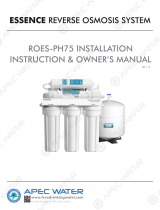
Installation Tips
How to Use the Quick-Connect Fittings
Figure 1
Press
Figure 3
Figure 2
Cut cleanly
and squarely
4
How to Drill a Hole into Your Sink or Countertop (Optional)
NOTE: Please confirm if there is an existing hole available to install the RO faucet.
If not, please drill a hole in accordance with the following steps.
It's highly recommended to watch the YouTube video "How to Drill a Faucet Hole" for a better understanding
of the process. There is also a reference sticker to help you drill the hole. Remember to wear safety glasses to
protect your eyes while drilling the faucet hole.
To disconnect:
• Remove the blue lock clip from the fitting;
• Use your thumb and index finger to press down the
lock sleeve. Use your other hand to pull out the tubing
from the fitting (Figure 3).
NOTE: Please do not pull out the tubing directly. This
will damage the fitting and cause leakage.
NOTE: If the tubing is too long, cut it to a suitable length
with a sharp utility knife or scissors. Cut the tubing
squarely and cleanly (Figure 2). Make sure the tubing is
fully inserted (about 0.8“).
To connect:
NOTE: There is an existing mark (Figure 1) at the end of the tubing for you to confirm if the
tubing is fully inserted into the fitting.
• Push the tubing into the fitting until you reach the mark on the tubing.
NOTE: If the tubing is not fully inserted, no seal will be created and leakage will occur.
• When the tubing is fully inserted, put the blue lock clip on the fitting. It will lock the tubing in
place and prevent it from falling off.

1. Choose a diamond core bit for granite, and a carbide drill bit for stainless steel. Do not use a hammer drill
on natural stone, glass or ceramic.
2. Glue the sticker on your sink or countertop, and drill a hole referring to the sticker hole size (1").
3. Make an indent with a center punch on a stainless-steel sink before drilling to help guide the bit.
4. Be careful when drilling on a porcelain sink, as it can be easily chipped. Apply downward pressure firmly
on the bit until you break through the surface.
5. Start at the lowest speed, and hold the drill straight with firm pressure to prevent the bit from walking on
the counter.
6. Once you break through the surface, swirl the drill a little to apply pressure in a circle evenly.
5
Figure 4
3/8’’ Cold Water Pipe
3/8’’ INPUT
Water Tubing
Unscrew
Unscrew
Feed Water Adapter
Washer
Cold Water
Supply Valve
Figure 5
1/2’’ Cold
Water Pipe
Prior to installation, it is highly recommended to watch the video "Waterdrop G3 RO Installation" on YouTube.
NOTE: • The RO system must be connected to the COLD water supply ONLY.
• Do not install the system in exposure to direct sunlight or harmful chemicals, nor any place where it may be
damaged.
• Do not install the system near any heat source.
• Do not install the system outdoors.
Step 1: Install the Feed Water Adapter (3/8" or 1/2”)
NOTE: The "INPUT" water tubing has been attached to the feed water adapter for easy installation.
1. Shut off the water supply. Turn on the kitchen faucet to release the water pressure;
NOTE: Make sure the water has stopped before proceeding to the next step. Get a towel or bucket to catch
any excess water.
2. Disconnect the cold water pipe from the cold water supply valve;
3. Twist the feed water adapter onto the cold water supply valve (with its washer) and tighten it with an
adjustable wrench (Figure 4);
NOTE: If the cold water pipe is 1/2", unscrew the two converters from the feed water adapter (Figure 5), and
then implement Step 3.
4. Twist the cold water pipe (with its washer) onto the feed water adapter and tighten with an adjustable wrench.
Installation Steps

Faucet Body
Faucet Spout
Faucet Power Cord
Mounting Washer
Countertop
Faucet Stem
Back Plate
Front Plate
Step 2: Install the RO Faucet (Non-Air Gap Faucet)
NOTE: If your kitchen sink or countertop does not have an existing hole, you will have to drill one (1”). Refer
to Page 5.
1. Insert the faucet spout into the faucet body (Figure 6)
2. Insert the faucet stem, power cord and filtered water tubing into the hole on countertop.
3. Under the sink, slip on the nut and tighten it up.
Step 3: Install the Drain Saddle
1. Paste the foam seal onto the front plate of drain saddle. Make sure the hole of foam seal is aligned with
the hole of front panel (figure 7). Choose a spot on the drain pipe that is convenient for installing the drain
saddle.
NOTE: It's recommended to install the drain saddle on the vertical drain pipe.
2. Drill a 1/4” hole in the drain pipe. Be sure not to penetrate the opposite side of the pipe.
3. Slip the front plate on one end of the tubing (without the mark), and insert the tubing into the drilled hole
for about 0.6” (Figure 8).
4. Position the back plate on the drain pipe by tightening the screws and nuts evenly while leaving the
tubing in the hole.
5. Pop the lock clip on the fitting to secure the connection (Figure 9).
NOTE: In some cases, the "WASTE" water tubing needs to be connected to the drainpipe through air gap.
Consumers need to purchase air gap accessories additionally.
6
Figure 7 Figure 9Figure 8
About 0.6’’
Foam Seal
Figure 6

c) If the partition is wood, the edges of the opening
specified in (b) should be smooth and rounded. If the
partition is metal, it should be covered with an edge
protector provided for this purpose by the manufacturer;
d) Care should be exercised when the appliance is
installed or removed in order to reduce the likelihood of
damage to the power cord.
7
Step 4: Position the RO System Housing
NOTE: It is not recommended to place the housing against the cabinet, as there may be vibrations when the
system works.
a) The power-supply receptacle for the appliance shall be installed in a cabinet or on a wall adjacent to the
undercounter space in which the appliance is to be installed.
b) There should be an opening through the partition between the compartments specified in (a) that is
large enough for the attachment plug to pass through. The longest dimension of the opening shall not be
more than 1.5” (38 mm).
Step 5: Connect Tubing
NOTE: Confirm the tubing length you need first, and then cut the tubing if it's too long, referring to "How to
Use the Quick-Connect Fittings" on page 4.
1. Install the “INPUT” Water Tubing
• Remove the plug from "INPUT" water port;
• Identify the white 3/8" PE tubing which has been attached to the feed water adapter (Figure 11);
• Insert the other end of the tubing into the "INPUT" water port (Figure 12), and pop the lock clip on the
fitting.
Figure 11
“ INPUT” Water Tubing
Feed Water Adapter
“ INPUT” Water Port
“ INPUT” Water Tubing
Lock Clip
Figure 12
Figure 10
17.72’’
18.12’’
5.67’’

2. Install the “FILTERED” Water Tubing
• Remove the plug from the "FILTERED" water port;
• Identify the white 1/4" PE tubing that is pre-installed with RO faucet (figure 13).
• Insert the other end of the tubing into the “FILTERED” water port (Figure 14), and pop the lock clip on the
fitting.
NOTE: Make sure it is fully inserted until you reach the mark on the tubing.
3. Install the “WASTE” Water Tubing
• Remove the plug from the "WASTE" water port;
• Identify the red 1/4" PE tubing which has been attached to the drain saddle (Figure 15);
• Insert the other end of the tubing into the "WASTE" water port (Figure 16), and pop the lock clip onto the
fitting.
NOTE: Make sure it is fully inserted until you reach the mark on the tubing.
Figure 13
Figure 15 Figure 16
Drain Saddle
“WASTE” Water Tubing
Lock Clip
“ FlLTERED” Water Port
“ FlLTERED”
Water Tubing
Lock Clip
“ FlLTERED” Water Port
“ FlLTERED”
Water Tubing
“ FlLTERED”
Water Tubing
“ WASTE” Water Port
“ WASTE” Water Tubing
Lock Clip
8
Figure 14

Step 6: Connect Power Cord
Connect the RO faucet to the system: Insert the power cord which is attached to the RO faucet into
the“FAUCET” connector (Figure 17) at the back of the housing, and tighten the nut.
Connect Power Adapter: Insert the DC head of the power adapter into the "POWER" port at the back of the
housing (Figure 18).
NOTE: Please do not connect power socket now.
Figure 19 Figure 20 Figure 21
Figure 17 Figure 18
“POWER” Port
Empty Circle Mark Solid Circle Mark
9
“FAUCET”Connector
Step 7: Install the Filters
Each filter is marked with a logo (CB/CF/RO) and an installation arrow.
1.Remove the wrapping and protective cap from the filter;
2.Insert the filter into its corresponding hole (Figure 19), align the arrow with the empty circle on the housing
(Figure 20);
3.Twist the filter with a little force forward in a clockwise direction for 90 degrees, until the arrow is aligned
with the solid circle on the housing (Figure 21). You may hear a clicking sound when the filter is fitted into
place properly;
4.Repeat the above steps to install the other two filters.

Step 8: Start up the System
1. Turn on the cold water supply valve. Check for leaks;
2. Insert the plug of power adapter into the socket;
NOTE: If the system can't be powered on after you insert the plug of power adapter, check the power under
the sink, as this mostly occurs when the power under the sink is powered off. Also, check the connection
between the plug and the power outlet, and ensure that the system has been plugged correctly into the
power outlet, as this may occur in a few cases. To test if there is a problem with the system itself, just pick up
the system and try another power outlet. Please contact us if the system can't be powered on. We will help
you figure it out.
3. The system starts flushing automatically for 5 minutes;
NOTE: After powering up for the first time, there will be one beep. The filter life indicators on front panel will
flash blue, yellow and red in turn and then turn blue for 5 minutes, the front screen displays flushing status
(Figure 22) at that moment. The faucet filter life indicator will flash white, yellow, red in turn for 1 second.
Then it turns white for 5 minutes. The faucet displays flushing status and the outer ring light will flash
clockwise dynamically (Figure 23). Do not turn on the RO faucet. Allow the system to flush automatically for
5 minutes. The three indicator lights will be off when the flush is complete.
NOTE: A slow water flow is normal if the RO faucet is turned on, and water is not drinkable during the
automatic flush.
4. Turn on the RO faucet. Allow it to run for 30 minutes until the front panel screen and faucet screen
start displaying a TDS reading (Figure 24);
NOTE: Be sure to carefully check the tightness of each part of the system while flushing. Check and ensure
all tubing is installed correctly and completely. Make sure there are no leaks at the joints, fittings, valves and
tubing connections.
NOTE: The water is not drinkable during the flushing. The 30 minutes are accumulative. If the flush is stopped
in advance, the system will continue to flush when you open the RO faucet again until it reaches 30 minutes.
Figure 22 Figure 23
TDS Reading
10
Figure 24
Flushing Status

Congratulations!
You have successfully installed the system!
Owner's Manual
Display and Operation
5. Confirm the flush is completed before turning off the RO faucet and ensure it’s not leaking.
6. Please fix the power adapter with the cable tie so that it does not move by impact. To avoid failure,
stay away from any water sources, including pipe fittings, the bottom of the basement, and wet floors.
* Please note that the reading in the figure is only used as an example, and the actual reading may vary
according to different water conditions.
* The TDS level shown on the panel after the system is just turned on is different from the actual TDS level
because the TDS reading needs some time to be upgraded.
Section 1: TDS Display
The built-in TDS sensor detects the water quality when the system begins to work, and shows the TDS
reading on the front panel display screen and faucet screen (Figure 25).
NOTE:
The system will provide above a 90% TDS rejection rate when working properly, which may vary with a
deviation of 10% depending on the source water quality and water usage. The TDS reading may vary as the
water is flowing.
The TDS display on front panel screen will go off after 5 minutes when the system stops dispensing water.
And the TDS display on RO faucet screen will go off after 1 minute when the system stops dispensing water.
During the first 10-30 seconds of water dispensing, the system is updating the TDS reading and there is
residual water in the filtered water tubing. Therefore, the actual TDS value will be higher than the TDS
reading on the screen.
* Please note that the reading in the figure is only used as an example, and the actual reading may
vary according to different water conditions.
11
Figure 25
TDS Reading

Activated Carbon Filter (CB)
Filter Life: Up to 12 months or 1,100 gallons
Pre-sediment and Carbon Block Filter (CF)
Filter Life: Up to 6 months or 550 gallons
Reverse Osmosis Membrane Filter (RO)
Filter Life: Up to 24 months or 2,200 gallons
Section 2: Filter Life Reminder
NOTE: Filter life may vary depending on source water quality and water usage. Please replace the filter
according to the reminder of the filter life indicators.
1. Filter Life Indicator on System Housing
There are helpful electronic filter indicators (CF/CB/RO) on the front panel (Figure 26) that will notify you to
perform a routine filter replacement by color change. Be sure to reset the filter life indicator every time you
replace your filter.
NOTE: The indicators will notify you according to the usage time or processing capacity of the filters,
whichever comes first.
Display Status:
Status Remaining
Life (Day)
Remaining
Capacity (G)
Indication
Light Buzzer
Beeps 2 times when
dispensing Water
Keeps beeping when
dispensing Water
N/A
Normal
Pre-warning
Warning
>15 >40
≤15 ≤40
≤0 ≤0
Blue
Yellow
Red
Figure 26
Replace Soon
Good Replace Now
12

Display Time:
• All indicators will go off after 5 minutes when the system stops making water.
• Check the filter life status by touching the indicators, and the lights will go off in 30 seconds.
2. Filter Life Indicator on the RO Faucet
Different light colors displayed on RO faucet indicate different filter life status. (Figure 27)
Section 3: Filter Replacement Guide
NOTE: If the filter expires, please purchase and replace the filter immediately. Otherwise, the filtration
efficiency will decrease significantly and affect the performance.
How to Replace Filters:
The filters could be replaced directly without cutting off the power and water supplies, and there will be no
water and electric leakage.
1. Before removing the filter, please turn off the faucet first and wait for 30s to fully release the internal
pressure of the RO system, which makes the filter easier to remove and install.
2. Twist off the filter that needs to be replaced in a counterclockwise direction (Figure 28).
NOTE: After replacing the CF and CB filter, it's recommended to press the center knob (Figure 29) protruding
at the top of the old RO filter to release the pressure to avoid water spills. Get a towel or bucket to catch any
excess water;
3. Twist the new filter into the housing in a clockwise direction;
4. Reset the filter life indicator and flush the filter after replacement (please refer to the following steps.)
Figure 27
13
Status
Replace Now
Flushing (Figure 30)
Malfunction (Figure 30)
Remaining Life (Day) Remaining Capacity (G)
Faucet Screen
>15
/
/
≤15
≤0
/
/
≤40
≤0
>40White Filter Life Indicator
Yellow Filter Life Indicator
Red Filter Life Indicator
White Flash
Red “Error”
Good
Replace Soon
Good Replace Soon Replace Now

How to Reset the Filter Life Indicator (Taking Reset of CB Filter Life Indicator as an Example):
Hold the CB filter life indicator for 7 seconds until the system beeps.
NOTE: Refer to the above method, hold down the CF or RO indicator to reset the corresponding filter.
How to Flush the Filter after Replacement:
NOTE: The display screen on front panel and RO faucet will show the flushing status (Figure 30) during the
process.
For CF filter: It will be flushed automatically for 5 minutes without turning on the RO faucet;
For CB filter: Turn on the RO faucet to flush for 15 minutes;
For RO filter: Turn on the RO faucet to flush for 30 minutes.
Section 4: Automatic Flushing
The system will be flushed automatically in one of the following situations:
1. Flush for Accumulative Working Time over 2 Hours
To maintain and extend the life expectancy of the filters, the system will be automatically flushed for 20
seconds after working for two hours. While flushing, the front panel screen will show a display similar to what is
in Figure 30. If the user decides to take water during the flushing, the system will quit flushing and switch to
dispensing.
2. Flush for Power Restore
When power is restored after a blackout, the system will be forced to be flushed automatically for 20 seconds.
While flushing, the front panel screen will display as seen in Figure 30. The blue, yellow, and red lights will
flash in turn for one second, and then the blue light will be on for 20 seconds. The indicators will be off when
the flushing is complete.
Figure 28 Figure 29
Figure 30
14
Flushing Status

3. Recycled Fresh Water Flushing
Recycled fresh water flushing function is to ensure each cup of water to be fresh and healthy. The system will
automatically recycle fresh water and start flushing after it has dispensed water over 5 minutes. When the
system is recycling fresh water and subjected to flushing, the panel displays as shown in figure 30.
Section 5: Malfunction Display
When the system is in fault, the malfunction indicates as follows:
• E02: For inside water leakage, the buzzer keeps beeping (Figure 31).
NOTE: Please pull out the water container at the back and check if there's any water. If there is, clean the
container and re-install it back. The malfunction should be fixed automatically. If E02 shows again shortly,
please contact the customer service hotline 1 -888-352-3558 Mon-Fri 8:00 AM-5:00 PM (PST) for assistance.
• E03: lf the booster pump overworks, the buzzer beeps for 3 minutes. The system will need to be powered
on again to recover;
• E04: lf the booster pump starts and stops frequently, the buzzer sounds 5 times. The system will need to be
powered on again to recover.
NOTE: Please refer to "Troubleshooting" for detailed solutions concerning malfunction code reminders.
Figure 31
1515
Malfunction
Code

System Maintenance
Troubleshooting
• If you don't use the system for more than one week, turn on the RO faucet, shut off the cold water valve,
and disconnect the power. Seal the filters and store it in the refrigerator (not the freezer). You need to open
the RO faucet and allow it to run for 10 minutes first before using the system again. Otherwise, you need to
replace the filters, as bacteria may grow when the system is not used for a long time.
• Please replace the filter regularly according to the filter life indicator.
NOTE: While the testing was performed under standard laboratory conditions, actual performance may vary
depending on the source water quality and water usage. In case of early blockage and failure of the filters,
it's recommended to replace the filter in accordance with the actual usage.
• Clean the system with clear water. Do not spray the water directly. Do not use steel wool, an abrasive
cleaner or corrosive liquid such as gasoline or acetone.
• When cleaning, do not pour other liquids into the filter to avoid damage to the filter system.
• Keep the waste water pipe unobstructed to avoid damage to the filter or internal components.
• When the drain pipe is blocked, do not use the system (please turn off the power) to avoid waste water
from soaking the floor.
• Check the system and water pipe fittings regularly for water leakage to avoid any property damage.
• Regularly check whether the power supply and wires are damaged or loose to avoid major accidents
caused by electric leakage.
• If you are using well water as the source, please ensure that the feed water has been through a pre-filtration
system. Otherwise, large particles in the well water will easily clog the filter and shorten the filter life.
• If the System Cannot Be Powered on After You Insert the Plug of Power
Adapter
a. Check the power under the sink, as this mostly occurs when the power under the sink is off. Also, check
the connection between the plug and the power outlet, and ensure that the system has been plugged
correctly into the power outlet, as this may occur in a few cases. To test if there is a problem with the system
itself, just pick up the system and try another power outlet. Please contact us if the system can't be powered
on. We will help you figure it out.
• No Output Water from RO Faucet
a. Filter expired. Check the filter life indicators to confirm which filter needs to be replaced and replace it
immediately.
b. Low water pressure. Check and confirm the water pressure is between 14.5 PSI and 87 PSI.
c. Water supply is off. Turn on the feed water adapter or water supply valve.
d. Incorrect filter installation. Re-install the three filters, and make sure they are fitted properly.
e. Tubing is crimped. Check all tubing and remove any crimps.
16
/