ISPRING F15-500 Operating instructions

Type
Operating instructions

This manual is also suitable for

iSpring Reverse Osmosis Water Filter Systems
COMMERCIAL REVERSE OSMOSIS SYSTEM
INSTALLATION INSTRUCTION
RCS5T
Ver 2015-10
Copyright ©2005-2015 ISPRING WATER SYSTEMS, LLC. All rights reserved.
Page 1
Please keep this owner’s manual for future reference.
It includes the information on how to properly operate and maintain your
iSpring Reverse Osmosis water filtration system.
TABLE OF CONTENT
BEFORE INSTALLATION.....................................................................................................................2
Inspect the package...............................................................................................................................2
Recommended tools list........................................................................................................................2
Operating conditions.............................................................................................................................2
Components Identification....................................................................................................................3
Installation Tips........................................................................................................................................4
How to use Quick-Connect fitting........................................................................................................4
To connect: .......................................................................................................................................4
To disconnect:...................................................................................................................................4
How to use Compression fitting with brass Nut, Collar, and tube Insert.............................................5
How to drill a hole on sink or counter-top............................................................................................5
Ice Maker Kit........................................................................................................................................5
Installation Steps.......................................................................................................................................6
Step 1: Install Feed Water Adapter (AFW)..........................................................................................6
Step 2: Install Drinking Water Faucet..................................................................................................7
Step 3: Install Drain Saddle..................................................................................................................7
Step 4: Install the Vertical Filters: Stages 1, 2, and 3...........................................................................8
Step 5: Install Tank Shut-off Valve (Optional) ....................................................................................8
Step 6: Install Reverse Osmosis Membrane.........................................................................................8
Step 7: Tubing Hook up (model specific sub-steps are marked with * )..............................................9
Step 8: System Start Up (model specific sub-steps are marked with * )..............................................9
SYSTEM MAINTENANCE..................................................................................................................11
Stages 1 – 3 pre-filters: Replace every 6 – 12 months, depending on source water quality and clean
water usage. ........................................................................................................................................11
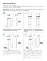
How to change in-housing cartridges in 1st – 3rd pre-filter stages....................................................11
Stage 4 RO membrane: Replace every 2 – 3 years or sooner if TDS level starts increasing.............12
How to change reverse osmosis membrane........................................................................................12
Stage 5 T33 fine carbon: Replace every 12 months...........................................................................12
How to change inline cartridges in 5th – 7th stages...........................................................................12
O-rings: Replace every 3 years or sooner if leak happens at O-ring..................................................12
Extra Installation.....................................................................................................................................13
UV Lamp (part# iSpring UVB11) and Ice maker kit (part# iSrping ICEK)......................................13
Page 2
BEFORE INSTALLATION
Inspect the package
Please open the box, and take all the components and tool kit out. Inspect them to ensure that nothing is
damaged during shipping. If any part is cracked or broken, please immediately contact iSpring Customer
Support for replacement. Identify and get familiar with the components.
Recommended tools list
Variable speed drill with two bits: ¼” (for drilling a hole on PVC drain pipe), ½” hollow diamond (for
drilling a hole on countertop for drinking faucet)
5/8”, 9/16” open-end wrench, or adjustable wrench, pliers
Phillips screwdriver
Scissors or utility knife
Operating conditions
Maximum water pressure: 80 psi, or pressure regulator (part no. APR70) is required if there is high
water pressure or water hammer)
Minimum water pressure: 40 psi, or booster pump is needed to improve RO efficiency
Water temperature: 40 – 100 °F (4 - 37 °C) (This RO system is NOT designed for HOT water)
Maximum TDS: 750 ppm
Install this RO system in a location where it is safe from hot/cold weather and direct sunlight. Avoid
hitting, falling, or dragging as they may cause cracks and leaks.
Page 3
Components Identification
Pre-assembled RO system (membrane not yet
installed, filter cartridges are still wrapped)
RO membrane, Installation tool kit, and spare parts
Page 4
Installation Tips
How to use Quick-Connect fitting
Figure 1
To connect:
1. See Figure 1. Check and cut the tubing end squarely and cleanly with utility knife or scissors.
2. Make a mark at the end of tubing. The lengh is about ½ inch, the depth of the fitting body.
3. Fully insert the tubing until the mark is about to disappear. This ensures that it is sealed by the
O-ring near the bottom.
Figure 2
Figure 3
To disconnect:
1. See Figure 2 and 3. Remove the blue Lock Clip.
2. With two fingers PUSHING IN and PRESSING DOWN the Lock Sleeve to eliminate the
Gap that the blue Lock Clip occupied, pull the tubing out. (Pressing down the Lock Sleeve
releases the spring-loaded steel teeth that grab the tubing inside the fitting body).
Page 5
How to use Compression fitting with brass Nut, Collar, and tube Insert
Compression fitting is used to connect the PVC tubing to the threaded metal inlet with a tapered open
end, such as the refrigerator water inlet, drinking faucet water inlet, etc.
Figure 4
1. Slide the Nut, Collar onto the end of tubing
2. Fully insert the Insert into the open end of tubing
3. Slide the Collar to be close to Insert and fit into the tapered open end of the thread matal inlet.
4. Screw on the Nut and tight it up. The Nut compresses the plastic Collar onto the tapered matal
surface and creates a water seal between them while the Insert hardens the tubing.
How to drill a hole on sink or counter-top
1. It’s highly recommended to watch the YouTube video “How To Drill Faucet Holes.”
2. Choose a half inch Diamond Core Bit for granite, and a titanium drill bit for steel. Do NOT use
a hammer drill on nature stone, glass, and ceramic.
3. An indent should be made with a punch on steel before drilling to help guide the bit.
4. Use caution when drilling on a Porcelain sink, as it could be easily chipped. Set drill speed on
slow. Press the bit downward firmly until breaking through the slippery surface.
5. Use coolant to disperse heat. Choose water for granite, and oil for steel. Use the Water Suction
Cup to hold coolant inside and prevent the drill bit from slipping.
6. Starting at slowest speed, hold the drill firmly and vertically and prevent the drill bit from
slipping on the counter.
7. Once breaking through the smooth surface, swirl the drill a little to apply pressure in a circle
evenly.
8. Be patient and deliberate. It can take 20 – 40 minutes to drill through one inch.
Ice Maker Kit
An Ice Maker Kit (part# iSpring ICEK) can be
purchased separately to feed RO water to refrigerator
and get crystal clear ice cubes and great tasting water
at ease. It could make Drinking Water Faucet not
absolutely necessary.
Page 6
Installation Steps
Before you begin installation, it is highly recommended that you watch the video
“iSpring reverse osmosis installation” on YouTube.
Note: Steps 1 – 7 are independent, and can be performed in any order.
Step 1: Install Feed Water Adapter (AFW)
1.1 See Figures above. Turn off the Cold Water Line via the cold Water Supply Valve (WSV) under the sink.
Open the kitchen faucet to release pressure and make sure water has stopped before proceeding to the next
step. Get a towel or bucket to catch any water drips. Disconnect Faucet water hose Connector (FC) pipe from
WSV.
1.2 Check O-ring inside AFW female end, and twist it onto WSV. Tighten it up using wrench or pliers.
1.3 Twist FC onto the male end of AFW. Turn the handle of AFW to cross (OFF) position. Turn on WSV slowly,
check and fix any leaks.
Page 7
Step 2: Install Drinking Water Faucet
2.1 If your kitchen sink does not have an existing ½” hole, you will have to drill one. (Refer to How to drill a
Hole on Sink or Counter-top). Wipe clean and dry the area.
(Contact us for larger front plate and
washer if the hole is too big to cover).
2.2 Remove blue protection film from the front plate, slip it on the faucet thread, and slip on the black rubber
washer. Insert the faucet thread portion into the hole. Optional plumber glue or sealer could be used.
2.3 Under the sink, tighten the back rubber washer, lock washer with nut.
2.4 (Refer to How to use compression fitting). Slip the compression fitting nut and collar on the tubing, push the
insert into the tubing, insert it into the faucet end, and tighten up the nut. Pull the tubing to check if it is
secure.
Step 3: Install Drain Saddle
3.1 Choose a spot on the drain pipe that is convenient for installing the drain saddle and tubing. Horizontal pipe
is recommended to minimize the dripping sound.
3.2 Drill a 1/4” hole on the drain pipe; paste the black sticky pad around the hole.
3.3 Cut the 1/4” tubing end a bit to make a 45 degree angle. Slip the plastic nut and front plate on the tubing.
Insert the tubing into the 1/4” hole on the drain pipe, install the back plate and tighten two screws with hex
nuts while the tubing remains in the hole.
3.4 Tighten the nut on the Drain Saddle by hand. Pull the tubing to check if it is secure.
Page 8
Step 4: Install the Vertical Filters: Stages 1, 2, and 3
4.1 Make sure that the O-ring is seated inside the groove
on top of the filter housing. Food-grade silicon jelly
may be used to help the O-ring stay in place and seal
better.
4.2 Filter cartridges are preserved in shrink wrap. Note
the direction sign on the sticker before removing the
wrap (GAC stage).
4.3 When placing the filter cartridge into its housing,
make sure it is centered and the knob protruding from
the bottom of the housing fits in the central hole of
the filter.
4.4 Screw the housing, with filters attached, onto the
housing caps (caps are pre-assembled on the machine
head). The cap also has a center knob which should
be inserted into the center hole of the filter cartridge.
Twist the housing on in a clockwise
direction by hand,
and then use a housing wrench to tighten it up for
about 1/4 – 1/2 turn. Do not over tighten. This can cause leaks and make it difficult to unscrew the
housing when replacing filters.
4.5
Follow the steps 1.1 – 1.4 to install the GAC and CTO filters. *Note* the second stage GAC is
the only filter that must go in a certain direction. Make sure that the end with the rubber washer
faces up, thereby attaching to the housing cap.
Step 5: Install Tank Shut-off Valve (Optional)
5.1 Optionally this RO system can be used with a 20 – 200 gallons storage tank. A tank helps meet the impulsive
high volume demand and build a commercial or whole house Reverse Osmosis solution.
5.2 Wrap 10 - 15 turns of Teflon tape clockwise (looking from top) onto the metal thread at the top of the tank.
5.3 Screw (clockwise) the Tank Shut-off Valve on and tighten up by hand. Do not over tighten.
5.4
An extra Tee fitting is needed for connecting the 5stage, tank and filtered water faucet.
Step 6: Install Reverse Osmosis Membrane
6.1 Open the membrane housing cap. A thick rubber band can be slipped on the housing body for better grip.
6.2 Find the inner end with 4 O-rings, cut open the end of sealed bag and use it to hold RO membrane to avoid
contamination, and firmly insert the membrane into the housing until the outer end with only 2 O-rings is
completely inside the housing. See Figure above.
6.3 Before twisting the housing cap back on, check that the O-ring is evenly snagged on the membrane
housing (cap does NOT have O-ring). Hang tight and tighten up for about 1 /4 – 1 /2 turns using a small
plastic housing wrench, but do not over tighten. DO NOT reconnect the tubing to inlet on cap at this point
(will do it in system start up).
Page 9
Step 7: Tubing Hook up (optional sub-steps are marked with * )
7.1 Facing the iSpring logo up front, the pre-filter 1st stage is located on the right hand side. Connect the
3/8”
tubing between Feed Water Adapter (AFW) and point A.
7.2 Connect the Flow Restrictor (point C) , which is a 3-inch long cylinder with a FLOW sign laying beside the
membrane housing, to the black Drain Saddle with ¼” tubing.
7.3 Connect the Post Carbon Filter FT15 5
th
stage (point B) to the RO faucet with ¼” tubing.
7.4 * If you have a RO storage tank, replace the elbow fitting at point D with a Tee fitting, reconnect the tubing
from the check valve to one T, and connect the other T with tank shut-off valve.
Step 8: System Start Up (optional sub-steps are marked with * )
8.1 Make sure that all tubings are not kinked. Prepare a bath towel and bucket to catch water drips.
8.2 To avoid the residual carbon dust in the first three stages from getting into the RO membrane, remove the
tubing to the inlet of the RO membrane housing cap. Flush the first three stages into bucket until the water
turns clear, and re-connect the tubing to the RO membrane. You may do this whenever you change the first
three stages. (Optional: disconnect the storage tank if you have one)
8.3 Plug in booster pump power. Turn on Feed Water Adapter valve (AFW), and then slowly turn on the cold
Water Supply Valve (WSV). Finish flushing the first 3 stages, and then reconnect the tubing to membrane
housing cap.
8.4 Check for leaks. The top 3 causes for leaks are 1) the tubing was not fully inserted into the quick-connect
fitting. 2) the O-ring was not in place or kinked. 3) the Housing/Cap was not tightened up or off threads.
Page 10
8.5 Turn on RO faucet. Within 5 minutes, RO water should start dripping. Let it run for at least 10 minutes. This
flushes the system. Water could be black due to fine carbon dust from new carbon filters (step 8.2 could be
taken to expedite the flush). It will turn clear with some air bubble. Shut off the RO Faucet. (Optional: turn
on the Tank Shut-off Valve and wait for the tank to be filled up).
8.6 * If you have installed an iSpring UV stage, plug in the UV power and observe if the RO faucet turns the UV
on/off through the Flow Sensor Switch.
8.7 The reverse osmosis membrane is the key part for the effective reduction of total dissolved solids (TDS) and
that product water shall be tested periodically to verify that the system is performing properly. If the TDS of
the source water is 100ppm, the RO water should be less than 10ppm (Rejection rate >90%).
8.8 Check for leaks daily for the first two weeks after installation. Furthermore, a tray can be put under the
system in case of any leaks, and a Flood Alarm can be used together for better protection.
Congratulations! You have successfully installed the
iSpring Reverse Osmosis Water Filtration System!
Start enjoying the cleanest water right from your tap!
Page 11
SYSTEM MAINTENANCE
For replacement filter cartridges, visit 123Filter.com or Google “Model replacement filter” online, in
which “Model” is the model number of the system, e.g. RCS5T.
Stages 1 – 3 pre-filters: Replace every 6 – 12 months, depending on
source water quality and clean water usage.
The frequency depends on the source water quality and clean water usage. They could last longer in city water, and
shorter in well water. Different areas have good or bad water. Some customers reported they had to replace the 1st
stage every 1-3 months when they saw through the clear housing where heavy sediments and particles turned the
white cartridge into dark brown. Some customers reported they could replace them every 12 months. To protect the
RO membrane in the 4th stage, it is required to replace the pre-filters at least every 12 months.
How to change in-housing cartridges in 1st – 3rd pre-filter stages
1. Shut off the water supply valve and tank valve, open the faucet to depressurize. Place a bucket
or towel under the unit to catch water spills.
2. If there is enough room under the sink and filter system is hung on wall, it could be easier to
twist the filter housing off without taking the unit off the wall. Otherwise, it could be easier to
pull the system out, lay it down and work towards the housing bottom. Please be careful with
tubing connections when pulling the system out.
3. Twist off the filter housing in a counter-clockwise direction when looking from the bottom.
Use a housing wrench (the bigger one) if necessary.
4. Refer to Installation Step 1.1 to install a new vertical filter cartridges and twist the housings
back on. Remember not to over tighten or it will be hard to open next time.
Page 12
Stage 4 RO membrane: Replace every 2 – 3 years or sooner if TDS level
starts increasing.
Check the TDS level at least once a month to monitor the system performance. The rejection rate should be above
90% (NSF/ASIN STANDARD 58 for RO water filter).
How to change reverse osmosis membrane
1. Reverse osmosis membrane usually last about 2 – 3 years, depending on the source water
quality, clean water usage and the replacement frequency of the three pre-filters.
2. To ensure system performance and water purity, filter cartridges must be replaced on schedule.
Use the TDS meter periodically to check rejection rate.
3. Shut off the water supply valve and (optional) tank valve, open the faucet to depressurize
4. Place a bucket or towel under the unit to catch water spills.
5. Remove the tubing from the inlet fitting on the membrane housing cap. Use a housing wrench
or by hand to twist off the housing cap in a counter-clockwise direction when looking from
inlet. Pull out the old membrane. Use scissors or pliers to apply leverage if necessary.
6. Clean the housing using hot water and optional scent-free dish soap. Rinse thoroughly. Cut
open the small end of the sealed bag of a new RO membrane, hold the new membrane with the
bag, and insert it into housing without touching the membane with your bare hand, which may
contaminate it.
7. Check the O-ring on the open end of the membrane housing. It is recommended to replace it
every 3 years to prevent leaks. Twist the membrane housing cap back on by hand. Use a
wrench for a final ¼ turn if necessary. DO NOT over tighten.
Stage 5 T33 fine carbon: Replace every 12 months
Unscrew the elbow fittings on both ends, put them on the new cartridge, and use new Teflon if necessary.
How to change inline cartridges in 5th – 7th stages
1. Please note that the 5th - 7th stages (model specific) have directions and each end may have a
different kind of fitting.
2. Disconnect the tubing from the Quick-Connect fitting, unscrew the fitting, unwrap a new
cartridge, replace the Teflon tape on
the fitting threads if necessary, follow the Æ sign on the
label to screw the correct fitting on each end, and reconnect the tubing.
O-rings: Replace every 3 years or sooner if leak happens at O-ring.
The package comes with 3 spare O-rings for the pre-filter housing, and 1 spare O-ring for the membrane housing.
Please save them with this manual.
Page 13
Extra Installation
UV Lamp (part# iSpring UVB11) and Ice maker kit (part# iSrping ICEK)
Figure 5 Flow Sensor Switch for UV lamp
The models with a UV stage have a “U” letter in model number, such as RCC7U, RCCAK-UV, RCC1UP-AK.
The UV module comes pre-installed on the models with UV. It should function out of the box. The images above are
for a better understanding about how the components are assembled and work together.
The Ice Maker Kit (model#: iSpring ICEK) can be purchased separately to feed RO water to a refrigerator and get
crystal clear ice cubes and great tasting water. It would make a Drinking Water Faucet not absolutely necessary.
  • Page 1 1
  • Page 2 2
  • Page 3 3
  • Page 4 4
  • Page 5 5
  • Page 6 6
  • Page 7 7
  • Page 8 8
  • Page 9 9
  • Page 10 10
  • Page 11 11
  • Page 12 12
  • Page 13 13
  • Page 14 14

ISPRING F15-500 Operating instructions

Type
Operating instructions
This manual is also suitable for

Ask a question and I''ll find the answer in the document

Finding information in a document is now easier with AI