
ULTIMATE REVERSE OSMOSIS SYSTEM
RO-PUMP INSTALLATION
INSTRUCTION
& OWNER’S MANUAL
All Rights Reserved © APEC Water Systems
www. FreeDrinkin gWater.com
Ver 1.0
A
ll
Rig
h
ts
Res
e
rve
d
© APEC
Wa
ter
S
ystems
w
ww
.F
r
ee
Drinki
n
g
W
at
er
.com
r
r
Ve
r
1.
0


Please keep this Owner’s Manual for future reference.
It contains useful information on how to maintain and care for your
APEC Reverse Osmosis water filter system.
TABLE OF CONTENT
1. Installation:
Preparation ................................................................... page 1
Filter housings assembly ................................................. page 5
Feed water connection .................................................... page 6
Drain saddle connection ................................................ page 10
Faucet mounting ............................................................ page 12
Connecting the whole system ......................................... page 13
2. Maintenance:
Filter change schedule & instructions ............................. page 19
3. Owner’s Manual - RO Basics:
System flow diagram ...................................................... page 24
Input water pressure: most important factor ................... page 25
TDS meter: testing your water quality ............................. page 25
Tank volume & delivery pressure ..................................... page 26
Misc. topics .................................................................... page 26
4. Trouble-shoot Guide:
RO Head diagram .......................................................... page 29
Humming noise ............................................................... page 30
No water at dispensing faucet ......................................... page 30
System slow shut-off ....................................................... page 31
TDS level higher than normal ......................................... page 33
Filter housing is leaking .................................................. page 34
Tank ball valve is leaking ................................................ page 35
Pure water still taste like Tap water ................................. page 35
Air bubble in cup or bottle when filling ........................... page 35
5. Other Information:
AirGap Faucet Installation ............................................. page 36
6. Warranty ........................................................................... page 38
Please keep this Owner’s Manual
f
or
f
uture re
f
erence.
It contains use
f
ul in
f
ormation on how to maintain and care
f
or your
A
PEC Reverse Osmosis water
f
ilter system.
TA
BLE OF CO
N
TE
N
T
1
.
I
n
s
t
a
ll
a
ti
o
n
:
Preparat
i
on ................................................................... page
1
Filter housings assembly ................................................. page
5
Feed water connection .................................................... page
6
Dr
a
in
sadd
l
e
co
nn
ec
ti
o
n ................................................ page 1
0
Faucet mount
i
ng ...........................................................
.
page
12
C
onnecting the whole system ......................................... page 1
3
2
.
M
aintenance:
Filter change schedule & instructions ............................. page 1
9
3
.
O
wner’s Manual - RO Basics:
System
f
low diagram ...................................................... page
24
I
nput water pressure: most important
f
actor ................... page
25
T
DS meter: testing your water quality ...........................
..
page
25
T
ank volume & delivery pressure .....................................
T
T
page 2
6
M
isc. topics .................................................................... page 2
6
4
.
T
rouble-shoot Guide:
TT
RO Head di
ag
ram ..........................................................
pa
ge
29
Humm
i
n
g
no
i
se ...............................................................
pa
ge
30
No water at di
sp
ensi
ng
f
aucet .........................................
pa
ge
30
Sy
stem slow shu
t
-off
.......................................................
pa
ge
31
T
DS level hi
gh
er than normal .........................................
pa
ge
33
Filter housi
ng
is leakin
g
..................................................
pa
ge
34
T
ank ball valve is leaki
ng
................................................
pa
ge
35
Pure water still taste like Ta
p
water .................................
pa
ge
3
5
A
ir bubble in cu
p
or bottle when
f
illi
ng
...........................
p
ag
e 3
5
5
.
Ot
he
r
In
fo
rm
at
io
n:
A
irGap Faucet Installation ............................................. page 36
6
.
W
arranty
W
W
...........................................................................
page
38

1
Thank you for choosing APEC reverse osmosis systems.
You now own the finest water filter in America.
Please read and become familiar with instructions and parts needed before proceeding with the
installation.
BEFORE INSTALLATION:
Inspect the system:
Please take the system and all the components out of the box. Inspect the system and all the
connection fittings carefully, make sure nothing is damaged during shipping. If any part is cracked
or broken, please do not proceed with the installation and contact APEC or your distributor for an
exchange or diagnosis.
Recommended tools list:
x Variable speed drill
x Drill bit:
1/4” (for the waste line), 1/8” (as pilot, not mandatory), and 1/2” (for standard
faucet hole, air-gap faucet requires 1&1/4” hole)
x 5/8”, 9/16” open-end wrench, or adjustable wrench, pliers
x Phillips screwdriver
x Utility knife, or scissors
x Teflon tape
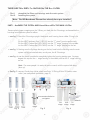
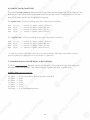
Operating Parameter
x Operating pressure: 0 - 30psi maximum
x Feed water temperature: 40 – 100 °F (4-37 °C)
x Feed water TDS level: 2000ppm maximum
x Do not connect this unit to hot water source
x Install the RO in a sheltered environment, avoid exposure to hot and cold weather or under
direct sunlight.
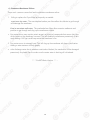
Copyright:
This manual is copyrighted by APEC Inc. Under the copyright laws, this manual may not be reproduced in any form, in
whole or part, without the prior written consent of APEC Inc. Manual print ver. 1.0, 2017 Dec.
General Installation/Operation/Maintenance Requirements
x Installation needs to comply with state and local laws and regulations.
x System must be installed indoor away from possible environmental damage
x Do not use with water that is microbiologically unsafe or of unknown quality without
adequate disinfection before or after system. Systems certified for cyst reduction may be
used on disinfected water that may contain filterable cysts.
x This reverse osmosis system contains a replaceable treatment component critical for
effective reduction of total dissolved solids. The product water shall be tested periodically to
verify that system is performing satisfactorily.
1
Thank you
f
or choosing APEC reverse osmosis systems.
Y
ou now own the
f
inest water
f
ilter in America.
Please read and become
f
amiliar with instructions and parts needed be
f
ore proceeding with the
in
s
t
a
ll
a
ti
o
n.
B
EFORE I
N
STALLATIO
N
:
I
nspect the system:
P
lease take the system and all the components out o
f
the box. Inspect the system and all the
c
onnection
f
ittings care
f
ully, make sure nothing is damaged during shipping. I
f
any part is cracked
o
r broken, please do not proceed with the installation and contact APEC or your distributor
f
or an
e
xchange or diagnosis.
R
eco
mm
e
n
ded
t
oo
l
s
li
s
t:
x
V
ariable speed drill
V
V
x
D
rill
b
it
:
1/4”
(f
or the waste line), 1/8” (as pilot, not mandatory), and 1/
2”
(f
or standard
f
aucet hole, air-gap
f
aucet requires 1&1/4” hole
)
x
5/8”, 9/16” open-end wrench, or a
dj
ustable wrench,
pl
iers
x
P
hillips screwdrive
r
x
U
tility kni
f
e, or scissors
x
T
eflon tape
T
T
Op
erating Parameter
x
Operating pressure: 0 - 30psi maximum
x
F
e
ed water temperature: 40 – 100 °F (4-37 °C
)
x
F
e
ed water TDS level: 2000ppm maximum
x
D
o
n
ot
connect this unit to h
ot
water sourc
e
x
I
nstall the RO in a sheltered environment, avoid exposure to hot and cold weather or unde
r
d
irect sunlight.
Copyright
:
This manual is copyrighted by APEC Inc. Under the copyright laws, this manual may not be reproduced in any
f
orm, in
whole or part, without the prior written consent o
f
APEC Inc. Manual print ver. 1.0, 2017 Dec.
G
eneral Installation/O
pe
ration/Maintenance R
eq
uirement
s
x
I
nstallation needs to comply with state and local laws and regulations.
x
System must be installed indoor away
f
rom possible environmental damag
e
x
D
o not use with water that is microbiologically unsa
f
e or o
f
unknown quality without
ade
qu
ate disin
f
ection be
f
ore or a
f
ter s
ys
tem. S
ys
tems certi
f
ied
f
or c
ys
t reduction ma
y
be
used on disin
f
ected water that may contain
f
ilterable cysts.
x
This reverse osmosis system contains a replaceable treatment component critical
f
or
eff
ective reduction o
f
total dissolved solids. The product water shall be tested periodically to
veri
f
y that system is per
f
orming satis
f
actorily.

2
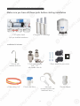
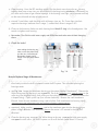
Components included with the RO system:
Make sure you have all these parts before starting installation.
1 RO system head
with pre installed membrane
3 Pre-filters in 3 Housings
1 Storage tank
Installation kit includes:
1 Faucet with
washers and nuts
1 Feed water adaptor
3/8”- 1/2”
with needle valve kit
1 Drain saddle for waste water
3 Color tubing 1/4”
1 Tank’s Ball Valve 2 Wrenches
for opening filter and
Membrane housing
1 Faucet Adapter
2
Components included with the RO system:
p y
Make sure you have all these parts be
f
ore starting installation
.
1 RO system head
with pre installed membran
e
3
Pre-
f
ilters in 3 Housings
1 Storage ta
nk
I
n
s
t
a
ll
a
ti
o
n kit in
c
l
udes:
1 Faucet with
washers and nuts
1 Feed water adapto
r
3
/8”- 1/2”
with needle valve ki
t
1
Dr
ai
n
sa
dd
le
f
or
w
as
te
w
at
er
3
Color tubing 1/4”
1 Tank’s Ball Valv
e
2 Wrench
es
Wre
f
or opening
f
ilter and
Membrane housi
ng
1 Faucet Ada
pt
e
r

3
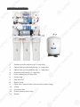
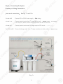
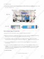
Component Itemization:
1) Sediment pre-filter and housing (1
st
-stage filter)
2) Carbon block pre-filter and housing ( 2
nd
-stage filter)
3) Carbon block pre-filter and housing ( 3
rd
-stage filter)
4) Membrane and housing (4
th
-stage filter)
5) In-line carbon filter (5
th
-stage filter)
6) Storage tank
7) Tank ball valve
8) Booster Pump
9) Check valve (Internal check valve encased in plastic fitting)
10) T-fitting
11) Feed water inlet
12) Product (filtered) water outlet
13) Bracket
3
Component Itemization
:
p
1) Sediment pre-
f
ilter and housing (
1
st
-
stage
f
ilter)
2)
Carbon block
pr
e-
f
ilter and housi
ng
(
2
n
d
-
sta
ge
f
ilte
r)
3
) Carbon block pre-
f
ilter and housing (
3
rd
-
stage
f
ilte
r)
4)
Membrane and housin
g
(4
th
-
sta
ge
f
ilte
r)
5) In-line carbon
f
ilter (
5
th
-
stage
f
ilter)
6)
Stora
ge
tan
k
7) Tank ball valve
8)
Booster Pum
p
9
) Check valve (Internal check valve encased in plastic
f
itting)
10
)
T-
f
ittin
g
11) Feed water inle
t
12
)
Product
(f
iltere
d)
water outle
t
13) Bracke
t

4
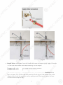
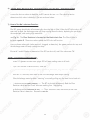
2. Metal compression nut fitting:
(comes with 1 insert, 1 sleeve, 1 nut) This is for feed water adapter
-needle valve only.
Fitting Types: There are 2 types of fittings provided for connecting the system
Important! Use plastic sleeve and inserts on the plastic tubing we
provide. Do Not use metal sleeve or insert on plastic tubing or the
connection will leak!
Fig.1B
How to connect: - See Fig.1B. Slide the compression nut onto the tubing.
- Slide the
plastic sleeve onto the tubing.
- Insert the “insert” into the tubing.
- Insert the tubing into the opening of the fitting.
- Slide the brass nut up, then tighten nut with a wrench. No Teflon tape!
(An extra metal sleeve is provided in case you need to connect your own metal
tubing. Use Teflon tape if connecting metal tubing.)
1. Quick-Connect (QC) fitting: (no insert, sleeve, or nut) Most of the fittings on the RO unit are this
type.
How to Connect: - See Fig.1. Push the tubing into the Quick-Connect fitting, then gently
pull back on the tubing to make sure connection was secure.
- No inserts, sleeve, or nuts are needed to secure the connection.
- No Teflon tape is needed!
To Disconnect: - See Fig.1A. Push in and hold down on the collet ring square against
the fitting. With the collet held in this position the tube can be removed.
Fig. 1
Fig. 1A
4
2. Metal compression nut
f
itting
:
(
c
omes with 1 insert
,
1 sleeve
,
1 nut
)
This is
f
or
f
eed water adapter
-needle valve only.
Fittin
g
Ty
pe
s:
There are 2 types of fittings provided for connecting the system
y
p
g
p
g
y
I
mportant!
Use plastic sleeve and inserts on the plastic tubing we
p
provide. Do Not use metal sleeve or insert on plastic tubing or the
connection will leak!
F
i
g.1
B
H
ow to connect: - See F
i
g.1B. Slide the compression nut onto the tubing.
-
S
li
de
th
e
plastic sleeve
o
nto the tubing.
-
In
se
rt th
e
“in
se
rt” into the tubing.
-
Insert the tubing into the opening o
f
the
f
itting.
-
Slide the brass nut up, then tighten nut with a wrench. No Te
f
lon tape
!
(
An extra metal sleeve is provided in case you need to connect your own metal
tubing. Use Te
f
lon tape i
f
connecting metal tubing.
)
1. Quick-Connect (QC)
f
itting
:
(
no insert, sleeve, or nut
)
Most o
f
the
f
ittings on the RO unit are this
type.
H
ow to Connect: - See F
i
g.
1.
Push the tubing into the Quick-Connect
f
itting, then gently
pull back on the tubing to make sure connection was secure.
- No inserts
,
sleeve
,
or nuts are needed to secure the connection.
- No Te
f
lon tape is needed
!
To Disconnect: - See Fig.1
A
.
Push in and hold down on the collet ring square against
the
f
ittin
g.
With the collet held in this
po
sition the tube can be removed.
F
i
g.
1
Fig. 1
A

5
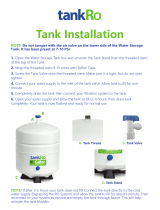
THERE ARE TWO PARTS TO INSTALLING THE RO SYSTEM:
Part I. Assemble the filters and housings onto the main system
Part II. Installing the system
Note: The RO Membrane Element has already been pre-installed.
PART I. ASSEMBLE THE FILTERS AND HOUSINGS ONTO THE MAIN SYSTEM
Remove plastic/paper wrappings on the 3 filters, put them into the 3 housings, and assemble the
housings onto the main system as follow:
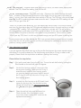
1. See
Fig. 2 Stand the 3 housings upright. Make sure each housing has a rubber O-ring in its
groove.
Put the APEC Sediment filter (1-SED10) into the “1
st
stage” housing on the right.
Put the APEC Carbon filter (23-CAB10) into the “2
nd
stage” housing in the middle.
Put the APEC Carbon filter (23-CAB10) into the “3
rd
stage” housing on the left.
2. See Fig. 3 Starting from the 3
rd
stage housing on the left, hand twist the housing onto the main
system turning counterclockwise, one by one, for all 3 housings.
3. See
Fig. 4 Use the wrench provided to completely tighten the housing starting from 1st-stage.
Repeat this step for the 2
nd
stage housing in the middle, and for the 3
rd
stage housing
on left.
Note: For some people it is easier to use the wrench with the system laid down
(face up).
4. See Pg. 3 Remove 2 end plugs (white color) from Point 10 Fitting & Point12 Product water
outlet ( see component itemization, page 3 )
Fig. 2
Fig. 3
Fig. 4
3rd
Stage
turn counter-clockwise
to tighten
3rd
Sta
g
e
2nd
Sta
g
e
1st
Sta
g
e
Use
Wrench
Us
e
5
THERE ARE TW
O
PART
S
T
O
IN
S
TALLIN
G
THE R
O
S
Y
S
TEM
:
P
a
rt I.
A
ssemble the
f
ilters and housings onto the main syste
m
P
a
rt II.
I
nstalling the syste
m
Note: The RO Membrane Element has already been pre-installed.
PART I. A
SS
EMBLE THE FILTER
S
AND H
OUS
IN
GS
O
NT
O
THE MAIN
S
Y
S
TE
M
R
emove plastic/paper wrappings on the 3
f
ilters, put them into the 3 housings, and assemble the
housings onto the main system as
f
ollo
w:
1
.
See
F
i
g. 2 Stand the 3 housings upright. Make sure each housing has a rubber O-ring in its
groo
v
e
.
P
ut the APEC Sediment
f
ilter (1-SED10) into the “
1
s
t
stage” housing on the right.
P
ut the APEC Carbon
f
ilter (23-CAB10) into the “
2
n
d
stage” housing in the middle.
P
ut the APEC Carbon
f
ilter (23-CAB10) into the “
3
r
d
stage” housing on the le
f
t.
2
.
See
F
i
g. 3 Starting
f
rom the 3
r
d
stage housing on the le
f
t, hand twist the housing onto the main
s
ystem turning counterclockwise, one by one,
f
or all 3 housings.
3
.
See
F
i
g. 4
U
se the wrench provided to completely tighten the housing starting
f
rom 1st-stage.
R
epeat this step
f
or the
2
nd
stage housing in the middle, and
f
or the 3
rd
stage housing
o
n l
ef
t.
N
ote
:
For some people it is easier to use the wrench with the system laid down
(f
ace up
).
4
. See Pg. 3
R
emove 2 end plugs (white color)
f
rom Point 10 Fitting & Point12 Product wat
er
outlet ( see component itemization, page 3 )
F
i
g.
2
F
i
g. 3
F
i
g. 4
3
r
d
S
tag
e
tu
rn c
ou
nter
-
c
lo
c
k
wis
e
t
o tig
h
te
n
3
r
d
S
ta
g
e
2
nd
S
ta
g
e
1
st
S
ta
ge
Us
e
W
r
W
e
n
ch
Us
e

6
PART II. INSTALLING THE SYSTEM
Space: Make sure there is sufficient space under the counter for installation (an area of about
17”L x 7”W x 18”H for the system, 11”D x 18”H or L for tank). The pressurized
tank can be installed on its side to save space.
The RO system is best installed under the kitchen sink. But if that is not feasible you
can install the system anywhere where there is a cold water supply with sufficient
water pressure for the chosen RO model, and an outlet to drain off the waste water
from the system.
Mounting: No need to mount the RO system on the wall. The RO system can stand in the sink
cabinet without mounting, this makes future filter change easy and convenient. If
you prefer to mount the system to the wall, please make sure it can be taken down
easily for filter replacement.
Feed Water: RO systems are designed to treat both hard and soft water and can handle incoming
TDS levels up to 2000ppm.
Step 1: Feed Water Connection
The RO system must be connected to the COLD water supply only!
1. Locate the Cold water supply valve under the kitchen sink (the round or oblong handle on
the right side). Turn off the incoming cold water completely by turning the shut off handle
clockwise.
Note: If the cold water shut off valve can not turn off the water, the main water supply
to the house must be shut off for the installation. Another option is to use a “self
piercing saddle valve” from APEC or from a local hardware store.
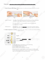
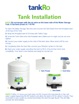
2. Feed Water Adaptor (1/2” or 3/8”): See Fig. 5. The Feed Water Adaptor comes with a
separate Needle Valve. The Adaptor goes inline onto your 1/2” or 3/8” cold water pipe. The
Needle Valve portion screws onto the Adaptor as shown in Fig. 5A.
Fig. 5
A. 1/2” x 3/8” Male-Female Water Supply Adapter
with O-ring.
B. 1/2” x 3/8” Male-Female Converter with O-ring.
C. 1/4” x 1/8” Male Needle Valve.
6
PART II. IN
S
TALLIN
G
THE
S
Y
S
TE
M
Sp
ace
:
Make sure there is su
ff
icient space under the counter
f
or installation (an area o
f
about
17”L x 7”
W
x 18”
H
f
or the system, 11”D x 1
8
”
H
o
r
L
f
or tank). The pressurized
tank can be installed on its side to save space.
The RO system is best installed under the kitchen sink. But i
f
that is not
f
easible you
c
an install the system anywhere where there is a cold water supply with su
ff
icient
water
pr
essure
f
or the chosen RO model, and an outlet to drain o
ff
the waste wate
r
f
rom the system.
M
ounting:
N
o need to mount the RO system on the wall. The RO system can stand in the sink
c
abinet
without mounting
g
, this makes
f
uture
f
ilter change easy and convenient. I
f
y
ou pre
f
er to mount the system to the wall, please make sure it can be taken down
e
asi
ly
f
or
f
ilter re
pl
acement.
Feed Water:
R
O systems are designed to treat both hard and so
f
t water and can handle incoming
TDS levels up to 2000ppm
.
Step 1: Feed Water Connectio
n
The RO system must be connected to the COLD water supply only!
y
pp
y
y
1. Locate the
Co
l
d
water supply valve under the kitchen sink (the round or oblong handle on
the ri
gh
t side
).
Turn o
ff
the incoming cold water com
pl
etely
by
turning the shut o
ff
handle
c
lockwise.
N
ote: I
f
the cold water shut o
ff
valve can not turn o
ff
the water, the main water sup
pl
y
to the house must be shut o
ff
f
or the installation. Another option is to use a “sel
f
piercing saddle valve”
f
rom APEC or
f
rom a local hardware store.
2
. Feed Water Adaptor (1/2” or 3/8”)
:
S
ee
F
i
g. 5. The Feed Water Adaptor comes with a
s
eparate Needle Valve. The Adaptor goes inline onto your 1/2” or 3/8” cold water pipe. The
N
eedle Valve portion screws onto the Adaptor as shown in Fig. 5
A
.
F
i
g.
5
A.
1/2” x 3/8” Male-Female Water Supply Adapte
r
with O-ring.
B. 1/2” x 3/8” Male-Female Converter with O-ring.
C
. 1/4” x 1/8” Male Needle Valve
.

7
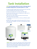
Fig. 5A - Needle Valve Installation.
Attach the needle valve (C) to water supply adapter (A). Please apply 5-6 wraps of
teflon tape to needle valve prior to connecting it to the water supply adapter (A).
Fig. 5B - If your pipe has a 1/2” Connection.
By attaching the 1/2” x 3/8” converter (B) to the Male end of the water supply adapter
(A), you now have a 1/2” Male and Female water supply adapter.
Fig. 5C - If your pipe has a 3/8” Connection.
By attaching the 1/2” x 3/8” converter (B) to the Female end of the water supply
adapter (A), you now have a 3/8” Male and Female water supply adapter.
Fig. 5A
Fig. 5B
Fig. 5C
1/2” Connection 3/8” Connection
7
Fig. 5
A
-
Needle Valve Installation.
Attach the needle valve (C) to water supply adapter (A). Please apply 5-6 wraps o
f
te
f
lon tape to needle valve prior to connecting it to the water supply adapter (A).
F
i
g. 5
B
-
I
f
your pipe has a 1/2” Connection.
B
y attaching the 1/2” x 3/8” converter (B) to the Male end o
f
the water supply adapte
r
(A
),
you now have a 1/2” Male and Female water sup
pl
y adapter.
Fig. 5
C
-
I
f
your pipe has a 3/8” Connection.
B
y attaching the 1/2” x 3/8” converter (B) to the Female end o
f
the water supply
adapter (A), you now have a 3/8” Male and Female water supply adapter.
Fig
.
5A
Fig 5
A
F
i
g. 5
B
Fig. 5
C
Connectio
n
1/2”
o
nnectio
n
3
/8” C
o

8
Riser
Tube
For Flexible Line
Faucet
Shank
Main Water
Supply
Shut-off
Valve
Riser
Tube
For Solid Line
Faucet
Shank
Needle
Valve
Needle
Valve
Main Water
Supply
Shut-off
Valve
Sink
Sink
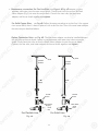
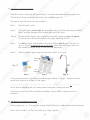
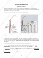
3. Recommend Connection For Flex Line Riser: See Fig.6A. & Fig. 6D. Loosen nut and
separate cold water riser tube from faucet shank. Gently bend riser tube so that the Feed
Water Adapter (Fig 5) fits onto the faucet shank. Connect the riser tube, the feed water
adapter, and faucet shank together and tighten.
For Solid Copper Riser: See Fig.6B. Follow the same procedure as for flex line. If the copper
riser cannot bend, then it’s best to replace it with a flex line riser. Then fit the feed water adaptor
the same way as described above.
Fig. 6A Fig. 6B
Option Connection Point: See Fig. 6E. The feed water adapter can also be installed between
the riser tube and faucet shank. Loosen nut and separate cold water riser tube from faucet
shank. Gently bend riser tube so that the Feed Water Adapter fits onto the faucet shank.
Connect the riser tube, feed water adapter, and faucet shank together and tighten.
8
Ri
Ri
se
se
r
Tu
Tu
be
be
F
o
r F
l
exi
bl
e Lin
e
Fa
u
cet
S
h
a
n
k
M
a
i
n
Wa
ter
Supp
ly
S
Sh
ut-off
V
Va
l
v
e
Riser
Tu
be
be
Fo
r
S
o
li
d
Lin
e
Fa
uc
et
S
h
an
k
Ne
ed
le
Va
l
v
e
Ne
ed
le
Va
l
v
e
Ma
in
Wa
te
r
r
Supp
ly
Shut
-o
o
ffff
Va
a
lv
v
e
e
S
in
k
S
in
k
3
. R
eco
mm
e
n
d
Co
nn
ec
ti
o
n F
o
r Fl
e
x Lin
e
Ri
se
r:
See
Fig.
6
A. & Fig.
6
D.
Loose
n n
u
t
a
n
d
s
eparate cold water riser tube
f
rom
f
aucet shank. Gently bend riser tube so that the Feed
Water Adapter (Fig 5)
f
its onto the
f
aucet shank. Connect the riser tube, the
f
eed wate
r
adapter, and
f
aucet shank together and tighte
n
.
For Solid Copper Riser:
See
F
ig
.
6
B. Follow the same procedure as
f
or
f
lex line. I
f
the coppe
r
riser cannot bend, then it’s best to replace it with a
f
lex line riser. Then
f
it the
f
eed water adapto
r
the same way as described abov
e.
Fig.
6
A Fig.
6B
Option Connection Point
:
See
Fig.
6
E. The
f
eed water adapter can also be installed between
the riser tube and
f
aucet shank. Loosen nut and separate cold water riser tube
f
rom
f
aucet
s
hank. Gently bend riser tube so that the Feed Water Adapter
f
its onto the
f
aucet shank.
Connect the riser tube,
f
eed water adapter, and
f
aucet shank together and tighte
n
.

9
Fig. 6C
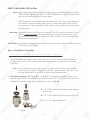
4. Needle Valve: See Fig. 6C. Screw the Needle Valve onto the Adaptor tightly. Apply 6-8 rounds
of Teflon tape onto Needle Valve before attaching it to the Adaptor.
To open needle valve: Turn needle handle counter-clockwise.
To close needle valve: Turn needle handle clockwise.
Test for leaks at this point: Close the Needle Valve (turn needle handle clockwise all the
way in to close) Turn ON the cold water supply to the sink faucet. If the Needle Valve or the
Adaptor leaks, check the connection and try applying more Teflon tape or tighten the brass
nut some more to stop the leak.
Fig. 6D Fig. 6E
9
Fig.
6C
4
. Needle Valve
:
See
Fig.
6C
. Screw the Needle Valve onto the Adaptor tightly. Apply 6-8 rounds
of T
eflon ta
pe
onto Needle Valve before attachin
g
it to the Ad
ap
to
r.
T
T
T
o
open
needle valve
:
T
urn needle handle counter-clockwise.
TT
T
o
c
l
ose
needle valve:
T
urn needle handle clockwis
e.
TT
Test for leaks at this point
:
p
Close the Needle Valve (turn needle handle
clockwise
a
ll th
e
way in to close) Turn ON the cold water supply to the sink
f
aucet. I
f
the Needle Valve or the
Adaptor leaks, check the connection and try applying more Te
f
lon tape or tighten the brass
nut some more to stop the leak.
Fig.
6
D Fig.
6
E

10
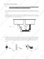
MOUNT DRAIN
SADDLE AT
EITHER
LOCATION
Step 2: Drain Saddle Installation
Note: To avoid annoying drainage noise, mount drain line as low as possible
on the vertical tailpiece, or on horizontal tailpiece.
There is constant water pressure “packed” inside the RO system which blocks the discharge
water from backing-up into the system. So the discharge water is “forced-drained”, not “gravity-
drained”.
1. See Fig.7. The drain saddle assembly should be installed above the trap and on the vertical
or horizontal tailpiece . To reduce the drainage noise, mount the drain line as low as possible
above the trap, or on the horizontal tailpiece.
2. See Fig.8. Mark the position of the hole on the drain pipe and drill a 1/4’’ hole through one
side of the drain pipe . There is a piece of self-adhesive sponge provided. Glue this sponge
to the inside of the saddle, this will cushion any gap between the saddle and the pipe. Make
sure the hole on the sponge is thoroughly punched out, and is aligned to the hole on the
saddle.
Fig. 7
Fig. 8 Fig. 9
1
0
M
O
UNT DRAIN
S
ADDLE
AT
E
ITHE
R
L
O
CA
TION
A
A
Step 2: Drain Saddle Installatio
n
N
ote
:
To avoid annoying drainage noise, mount drain line as low as possible
yg g , p
on the vertical tailpiece, or on horizontal tailpiece.
p , p
There is constant water pressure “packed” inside the RO system which blocks the discharge
water
f
rom backing-up into the system. So the discharge water is “
f
orced-drained”, not “gravity-
d
r
a
in
ed
”.
1
. See Fig.7. The drain saddle assembly should be installed above the trap and on the vertical
o
r horizontal tailpiece . To reduce the drainage noise, mount the drain line as low as possible
above the trap, or on the horizontal tailpiece.
2
.
See
F
i
g.8. Mark the position o
f
the hole on the drain pipe and drill a 1/4’’ hole through one
s
ide o
f
the drain
pi
pe
. There is a
pi
ece o
f
sel
f
-adhesive s
po
ng
e
pr
ovided. Glue this
sp
on
ge
to the inside o
f
the saddle, this will cushion any gap between the saddle and the pipe. Make
s
ure the hole on the sponge is thoroughly punched out, and is aligned to the hole on the
sadd
l
e
.
F
i
g.
7
F
i
g. 8 F
i
g.
9

11
3. See Fig.9, 9A. Make sure to align the drain saddle hole to the drilled hole perfectly.
Mis-aligning these two holes will block the drain water and cause membrane damage. Attach the
drain saddle to the drain pipe and tighten the two screws evenly.
4. Once the drain saddle is secured, push 1/4” black drain tubing into the Quick Connect fitting on the
saddle. DO NOT use a “Insert” on the drain tubing.
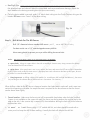
Step 3: Drill A Hole For The RO Faucet
Drill 1/2” diameter hole for standard RO faucet. (Air-Gap faucet: drill 1&1/4” hole.)
For best results use a 1/2” carbide-tipped masonry drill bit.
Wear safety glasses to protect your eyes while drilling the faucet hole.
Note: No need to drill a hole if an existing hole is available:
a) Spare hole: If there is a spare hole in the sink covered by a chrome cover, simply remove the chrome
cover and install the RO faucet there.
b) Spray hose: If the spray hose is not in use, remove the hose, and mount the RO faucet there. Remember
to plug up the outlet under the main faucet. If the spray hose uses a diverter at the base of the spout, be sure
to remove it to avoid trouble later on.
c) Hanging faucet: If drilling a hole is not feasible (i.e. rental home, drill tool not available etc.), the faucet
can just hang on the cabinet door or wherever that is convenient. Be creative!
When drilling a hole for the RO faucet, choose a location that looks good, works well, and is most con-
venient for dispensing pure water. An ample flat area is required for the faucet base so that the faucet
can be drawn down tightly.
1. Faucet location: Make sure the faucet stud will be accessible from below when the hole is drilled.
If space is not available on the upper sink area, the faucet can be located on the counter top by the
edge of the sink. If the counter top is ceramic tile, the method for drilling the hole will be the same as
for porcelain sinks.
2. For Stainless Steel Sink: Before using a 1/2” carbide drill bit, an indent should be made with a
center punch to keep the drill bit from walking. A small pilot hole will also aid the drill bit.
Fig. 9A
11
3
. See Fig.9, 9
A
.
Make sure to align the drain saddle hole to the drilled hole perfectly
g
p
y
.
y
y
Mis-aligning these two holes will block the drain water and cause membrane damage. Attach th
e
drain saddle to the drain
p
ip
e and ti
gh
ten the two screws evenl
y.
4
. Once the drain saddle is secured, push 1/4” black drain tubing into the Quick Connect
f
itting on the
sadd
l
e
. DO
N
OT
use a “Insert” on the drain tubing.
Step 3: Drill A Hole For The RO Fauce
t
Drill 1/2” diameter hole
f
or standard RO
f
aucet.
(A
ir-G
ap
f
aucet: drill 1&1/4” hole
.)
For best results use a 1/2” carbide-tipped masonry drill bit.
Wear sa
f
ety glasses to protect your eyes while drilling the
f
aucet hole.
N
ote
:
No need to drill a hole if an existi
ng
hole is available:
g
a)
Sp
are hole
:
I
f
there is a spare hole in the sink covered by a chrome cover, simp
ly
remove the chrome
c
over and install the RO
f
aucet there.
b
)
Sp
ra
y
hose: I
f
the
sp
ra
y
hose is not in use, remove the hose, and mount the RO
f
aucet there. Remembe
r
to plug up the outlet under the main
f
aucet. I
f
the spray hose uses a diverter at the base o
f
the spout, be sure
to remove it to avoid trouble later on.
c
)
Hanging
f
aucet:
If
drilling a hole is not
f
easible (i.e. rental home, drill tool not available etc.), the
f
auc
et
c
an just hang on the cabinet door or wherever that is convenient. Be creative
!
When drilling a hole
f
or the RO
f
aucet, choose a location that looks good, works well, and is most con
-
venient
f
or dispensing pure water. An ample
f
lat area is required
f
or the
f
aucet base so that the
f
aucet
c
an be drawn down tightly.
1.
Fa
uc
et
l
oc
at
io
n:
M
ake sure the
f
aucet stud will be accessible
f
rom below when the hole is drilled.
If
space is not available on the upper sink area, the
f
aucet can be located
on
the counter top by the
e
dge o
f
the sink. I
f
the counter top is ceramic tile, the method
f
or drilling the hole will be the same as
f
or porcelain sinks.
2.
Fo
r
St
ai
nl
es
s
St
ee
l
Si
nk
:
Be
f
ore using a 1/2” carbide drill bit, an indent should be made with a
c
enter punch to keep the drill bit
f
rom walking. A small pilot hole will also aid the drill bit.
Fig. 9
A

12
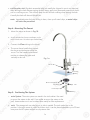
Black Locating Washer
Lock Washer
Lock Nut
Faucet Adapter
Tubing
Counter Top
Counter Top
Opening
Chrome Base
Step 4: Mounting The Faucet
1. Mount the faucet as shown in Fig.10.
Fig. 10
2.
Attach threaded end of faucet adapter to the
faucet metal stem. No teflon tape needed here.
3. Connect the Clear tubing to the faucet.
4. The faucet has a handle that controls
the flow of purified water exiting the
faucet. Turn the handle to horizontal
position to release the water and
vertically to shut off.
3. For Porcelain Sink: Porcelain enameled sinks can readily be chipped if care is not exercised
when drilling the hole. Before starting the drill motor, apply firm downward pressure on the bit
until a crunching occurs. This will help keep the drill bit from walking when starting the hole.
A small pilot hole will also aid the drill bit.
Note: Immediately after the hole drilling is done, clean up all metal chips, as metal chips
will stain the porcelain!!
Step 5: Positioning The System
1. Main System: The main system can stand in the sink cabinet. No need
to mount the system to the wall. If you prefer to mount the system to the
wall, please make sure it can be taken down easily for filter replacement.
2. Tank: The storage tank can also lay on its side if needed. The tank works fine in this
position. If the tank cannot fit under the kitchen sink, it can be placed elsewhere up to 20 feet
away from the RO system without much pressure loss.
1
2
Bl
ac
k
Locati
ng
Was
h
e
r
L
oc
k
Wa
s
h
e
r
L
oc
k
N
u
t
LkN
t
F
a
u
cet A
d
ap
t
e
r
T
u
b
in
g
C
ounte
r
T
o
p
C
ounte
r
To
p
O
penin
g
C
hr
o
me
B
a
se
Step 4: Mounting The Fauce
t
1. Mount the
f
aucet as shown in F
i
g.10.
F
i
g. 1
0
2
. Attach threaded end o
f
f
aucet ad
ap
ter to the
f
aucet metal stem. No te
f
lon tape needed here.
3
. Connect the
C
l
ea
r tubing to the
f
aucet.
4
. The
f
aucet has a handle that controls
the
f
low o
f
puri
f
ied water exiting the
f
aucet. Turn the handle to horizontal
position to release the water and
vertically to shut o
ff
.
3
.
F
o
r P
o
r
ce
lain
S
ink
:
Porcelain enameled sinks can readily be chipped i
f
care is not exercised
when drilling the hole. Be
f
ore starting the drill motor, apply
f
irm downward pressure on the bit
until a crunching occurs. This will help keep the drill bit
f
rom walking when starting the hole.
A small pilot hole will also aid the drill bit.
N
ote
:
Immediately a
f
ter the hole drilling is done, clean up all metal chips, as metal chips
will stain the porcelain!
!
Step 5: Positioning The Syste
m
1
.
M
ain System
:
The main system can stand in the sink cabinet. No need
to mount the system to the wall. I
f
you pre
f
er to mount the system to the
wall,
pl
ease make sure it can be taken down easi
ly
f
or
f
ilter re
pl
acement.
2
.
Ta
nk: The storage tank can also lay on its side i
f
needed. The tank works
f
ine in this
position. I
f
the tank cannot
f
it under the kitchen sink, it can be placed elsewhere up to 20
f
eet
away
f
rom the RO system without much pressure loss
.

13
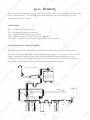
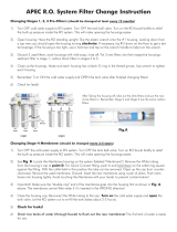
Step 6: Connecting The System
Summary of Tubing Connections:
There are 4 connections: See Fig. 11 and 11A
Point A to X: Connect RO to COLD water supply — Red tubing.
Point G to Y: Connect product water from 5
th
-stage filter to tank — Yellow tubing. This tubing
is a 2-way line, Product water enters and leaves the tank via this line.
Point H to Z: Connect product water from 5
th
-stage output to RO faucet — Clear tubing.
Drain line to W: Connect discharge water from 4
th
-stage membrane to drain outlet — Black tubing.
Fig. 11
1
3
Step 6: Connecting The Syste
m
Summary o
f
Tubing Connections:
T
h
e
r
e
a
r
e
4
co
nn
ec
ti
o
n
s:
See Fig. 11 and 11A
Po
int
A
to
A
X
:
Connect RO to COLD water supply — R
ed
tubing.
Po
int
G
t
o
Y
:
Connect product water
f
rom
5
th
-
stage
f
ilter to tank —
Yellow
tubing. This tubing
w
i
s a 2-way line, Product water enters and leaves the tank via this line.
Po
int
H
t
o
Z
:
Connect product water
f
rom 5
th
-
stage output to RO
f
aucet
—
Clea
r
tubing.
r
D
r
a
in lin
e
t
o
W
:
Connect discharge water
f
rom
4
th
-
stage membrane to drain outlet —
Black
tubing.
k
F
i
g. 1
1

14
Drinking Water Faucet
Pressurized
Holding Tank
Fig. 11A
Details on Tubing Connections:
To ensure a smooth and correct installation, please connect the water lines following the
sequence and order outlined below. Refer to Fig.11 & 11A for proper point locations.
1. Point Z Faucet connection:
Tubing color: Clear tubing. Connect the CLEAR tubing to the base of the RO faucet.
Fitting type: Quick Connect Fitting. Simply push Clear tubing into Quick Connect fitting. No Insert,
Sleeve or Nut needed here. (Attach threaded end of faucet adapter to the faucet metal
stem. No teflon tape needed here)
2. Point X Feed water connection:
Tubing color: Red tubing. Connect the RED tubing to the Feed Water Needle Valve.
Fitting type: Metal compression nut fitting.
See Fig.1B on page 4. Use plastic sleeve.
Add “insert” to tubing. No teflon tape here. Tighten nut with wrench.
1
4
Drin
k
i
ng
Water Fau
cet
P
ress
u
rize
d
H
o
ld
ing Tan
k
i
g.
1
1A
F
Details on Tubing Connections:
To ensure a smooth and correct installation, please connect the water lines
f
ollowing th
e
sequence and order
outlined below. Refer to
r
Fig.11 & 11
A
for proper point locations.
A
1
. P
oi
nt Z F
auce
t
co
nn
ec
t
io
n
:
Tubing color: Clear tubing. Connect the CLEAR tubing to the base o
f
the RO
f
aucet.
F
itting type:
Q
uick Connect F
i
tting. Simply push Clear tubing into Quick Connect
f
itting. No Insert,
Sleeve or Nut needed here. (Attach threaded end o
f
f
aucet adapter to the
f
aucet metal
s
tem. No te
f
lon tape needed here
)
2
. P
oi
nt X Feed water connection
:
Tubing color
:
R
e
d tubing. Connect the RED tubing to the Feed Water Needle Valve.
F
ittin
g
ty
pe
:
M
etal co
mp
ression nut
f
ittin
g
.
See
F
i
g.
1B
on
pa
ge
4
.
Use
pl
astic sleeve.
A
dd
“in
se
r
t”
to tubi
ng
. No te
f
lon t
ap
e here. T
ig
hten nut with wrench.

15
3. Point W Discharge water connection:
Tubing color: Black tubing. Connect the BLACK tubing from the RO to the Drain Saddle.
Fitting type: Quick-Connect fitting on drain saddle. No teflon tape.
Do Not add ”insert” into Black tubing. Simply push tubing into port.
4. Point A System water inlet (to Stage 1 pre-filter) connection:
Tubing color: Red tubing. Connect the RED tubing from the Feed Water Valve to the RO’s stage -1
pre-filter.
Fitting type: Quick Connect fitting See Fig.1 on page 4. Simply push the Red tubing into the Quick
Connect fitting. No Inserts, Sleeves or Nuts are needed to secure the connection. No
teflon tape is needed here.
5. Point H Stage-5 filtered water to faucet connection:
Tubing color: Clear tubing. Connect the CLEAR tubing from the faucet base stud to the Stage-5 filter’s
outflow end at point H. (See “Flow -->” arrow on the filter for flow direction.)
Fitting type: Quick Connect fitting
See Fig.1 on page 4. Simply push the Clear tubing into outlet
on the 5th stage filter. No Inserts, Sleeves or Nuts are needed to secure the
connection. No Teflon tape is needed here.
Please Note: There is an end plug on the Stage-5 filter output and Tee fitting that has to be re-
moved before inserting the tubing. Please refer to Fig. 1A on page 4 for removal instruction.
6. Point G Stage-5 filter’s T-fitting connection:
Tubing color: Yellow tubing. Connect the YELLOW tubing to Stage-5 filter’s T-fitting.
Fitting type: Quick Connect fitting
See Fig.1. Simply push the Yellow tubing into the 5th stage filter’s
T Fitting. No Inserts, Sleeves or Nuts are needed to secure the connection. No Teflon tape
needed here.
(Note: If the unit comes with a UV Light, connect the Yellow tubing to the T- fitting on the
UV, as the Stage 5 filter will not have a T-fitting).
15
3
.
P
oint
W
Discharge water connection
:
Tubing color
:
B
lack tubing. Connect the BLACK tubing
f
r
om
th
e
R
O
t
o
th
e
Dr
a
in
Sadd
l
e
.
F
itting type:
Q
uic
k
-
Connect
f
itting on drain saddle. No te
f
lon tape.
Do
N
ot
add
”in
se
rt” into Black tubing. Simply push tubing into port.
4
. P
o
int
A
System water inlet (to Stage 1 pr
e
-f
ilter) connection
:
Tubing color
:
R
e
d tubing. Connect the RED tubing
f
r
o
m the Feed Water Valve to the RO’s stage -1
pre-
f
ilter.
F
itting type: Quick Connect
f
itting See Fig.1
on
page
4
. Simply push the Red tubing into the Quick
Connect
f
itting. No Inserts, Sleeves or Nuts are needed to secure the connection. No
te
f
lon tape is needed here.
5
. P
oi
nt
H
Stag
e
-
5
f
iltered water to
f
aucet connection
:
Tubing color
:
Clear tubing. Connect the CLEAR tubing
f
r
o
m the
f
aucet base stud to the Stage-5
f
ilter’s
outflow
e
n
d
a
t
w
po
i
nt
H.
(
See “Flow --
>
”
arrow on the
f
ilter
f
or
f
low direction.)
F
itting type: Quick Connect
f
itting See Fig.1
on
page
4
. Simply push the Clear tubing into outlet
on the 5th stage
f
ilter. No Inserts, Sleeves or Nuts are needed to secure the
connection. No Te
f
lon t
ap
e is needed here.
Please Note: There is an end plug on the Stage-5 filter output and Tee fitting that has to be re
-
moved before inserti
ng
the tubin
g.
Please refer to Fi
g.
1A on
p
ag
e 4 for removal instruction.
6
. P
o
int
G
Stag
e
-
5
f
ilter’s T-
f
itting connection
:
Tubing color
:
Y
ellow tubing. Connect the YELLOW tubing to Stage-5 filter’s T-fitting.
Y
Y
F
itting type: Quick Connect
f
itting See Fig.
1.
Simply push the Yellow tubing into the 5th stage
f
ilter’s
T Fitting. No Inserts, Sleeves or Nuts are needed to secure the connection. No Te
f
lon tape
n
eeded
h
e
r
e
.
(
N
ote
:
I
f
the unit comes with a UV Ligh
t
, connect the Yellow tubing to the T-
f
itting on the
UV, as the Stage 5
f
ilter will not have a T-
f
itting
).

16
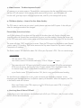
Ball Valve
(Recommended)
Tee tting for icemaker & output
H
Y
G
X
A
Z
7. Point Y Tank’s input & output connection:
Prepare tank: See Fig.12. Apply 6-8 wraps of Teflon tape to tank’s threaded Output stem on top of
tank (remove rubber cap if there is one). Screw tank Valve onto Output stem.
Tubing color: Yellow tubing. Connect the YELLOW tubing from Stage-5 T-fitting to the tank’s valve.
Fitting type: Quick-Connect fitting on ball valve. Simply push Yellow tubing into valve port.
Air pressure: The 4 gallon tank comes pre charged at 5 psi, 14 gallon tank at 7 psi.
Fig. 12
OFF Position ON Position
Tank Ball
Valve
(Off Position)
Air Valve
(Do not need
to touch)
Base Stand
(Optional)
Tank Ball Valve
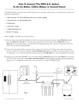
Option: Ice-maker Connection
If you want to connect product water from the RO to your ice-maker, you will need:
x One T-fitting, preferably the quick-connect type fitting
x Extra ¼ “ tubing long enough to go from the RO system to your ice-maker
x Optional: One shut-off valve, preferably the quick-connect type.
See Fig.13. Before connecting the product water line from Point Z to H, add a T-fitting near
point H to divert product water to both the ice-maker and the faucet. It is best open the line to
the ice maker after the first tank has been discarded and the 2nd tank has completely filled.
Standard 4-gallon Tank Diagram:
Refrigerator
Fig. 13
1
6
B
a
l
l V
alve
(
R
ec
o
mmen
d
e
d
)
Te
e
tt
ing for icemaker & outp
u
t
H
Y
G
X
A
Z
7.
P
oi
nt Y
T
ank’s input & output connection:
T
T
P
repare tank
:
See
F
i
g.12.
Apply 6-8 wraps o
f
Te
f
lon tape to tank’s threaded
Output
p
stem on top o
f
tank (remove rubber cap i
f
there is one). Screw tank Valve onto Output stem.
Tubing color
:
Y
ellow tubing. Connect the YELLOW tubing
Y
Y
f
r
om
Stage-5 T-
f
itting to the tank’s valv
e.
F
itting type:
Q
uic
k
-
Connect
f
itting on ball valve. Simply push Yellow tubing into valve port.
A
ir
pr
essure
:
The 4
ga
llon tank comes
pr
e char
ge
d at 5
ps
i, 14
ga
llon tank at 7
p
si.
F
i
g.
1
2
O
FF P
os
iti
on
ON
Positio
n
Tank Ball
Ta
Ta
TaTa
Ta
nk
nk
nk
nk
nk
B
B
B
B
B
al
al
l
l
Va
Va
Va
Va
Va
l
l
lv
e
(O
Off
Posit
io
o
n)
n)
ve
A
Ai
Ai
A
A
r
r
Va
Va
a
a
lv
eed
(D
(D
(D
(D
o
o
no
no
n
t
t
t
ne
h
)
to
to
o
t
t
t
t
t
ou
ou
ou
ouou
ou
ou
ou
ou
ou
ou
ou
ch
ch
B
ase
S
ta
an
d
(Optio
n
nal
nal
)
)
)
T
ank Ball Valv
e
Option:
p
I
ce
-m
a
k
e
r
Co
nn
ec
ti
on
If
you want to connect product water
f
rom the RO to your ice-maker, you will nee
d:
x
One T-
f
itting, pre
f
erably the quick-connect type
f
itting
x
Extra ¼ “ tubing long enough to go
f
rom the RO system to your ice-make
r
x
Optional: One shut-o
ff
valve, pre
f
erably the quick-connect type.
See
Fig.13. Be
f
ore connecting the product water line
f
rom Point
Z
t
o
H
, add a T-
f
itting nea
r
point H to divert product water to both the ice-maker and the
f
aucet. It is best open the line to
the ice make
r
after
the first tank has been discarded and the 2nd tank has completely filled.
r
Standard 4-gallon Tank Diagram
:
R
e
f
rigerato
r
F
i
g. 13

17
Using RO for Ice-maker only:
If you want the RO to feed your ice-maker (fridge) only, you should still connect the RO faucet
as a 2nd outlet. This allows you to drain the tank, flush new filters through the faucet rather than
through your icemaker line. You can hang the faucet by the system and not mount it.
Option: Multiple Outputs - Add Shut Off Valve:
If your RO is feeding several output points (icemaker, fridge, bathroom), you should add a
Shut-Off valve to each output line (except the RO spigot line). This way, if you ever need to
diagnose a problem in the system, you can easily shut off these lines to isolate the water flow for
accurate troubleshooting.
Step 7: System Start-Up
IMPORTANT: The Feed Water Supply must be Turned On before connecting the booster pump
to power. Running the pump dry may cause pre mature failure.
1. Turn on feed water: Slowly, turn on your Cold water supply. Turn on the Needle Valve (turn
counter-clockwise) to allow the raw water to enter the system. Check for leaks!
2. Plug in Pump Transformer: The Transformer and the Pump each has a “plastic connector
piece”. Join these 2 pieces together to connect the Transformer to the pump. Connect the
Pump’s Transformer into an electrical outlet. This will activate the Booster Pump on the system.
3. Turn on tank valve: Turn on the tank’s ball valve to allow water to enter the tank. The
tank’s valve is “ON” when the valve handle is parallel (in the same direction) with the valve’s
outlet (see Fig.12). Check for leaks!
4. Wait for tank to fill: Before usage, allow the tank to fill. Tank normally takes 2-3 hours to
fill. When the tank is filled, the RO will shut off automatically.
Tips!
If Point X (feed water adapter) leaks after you have tightened the brass nut, check to
make sure you did install the plastic “insert” and “sleeve” into the tubing. If the insert
and sleeve is already in place, then try applying Teflon tape from the threaded metal stud
all the way to the plastic tubing, wrap the whole connection with 8-10 rounds of Teflon
tape. Smooth out the tape on the threaded part with your fingers. Tighten brass nut
again. This should stop the leak.
If Point Y (tank ball valve) leaks, please make sure there was 6-8 wraps of Teflon tape
applied onto the tank metal stem before screwing on tank ball valve.
17
Using RO
f
or Ice-maker only:
If
you want the RO to
f
eed your ice-maker (
f
ridge) only,
y
ou should still connect the RO
f
aucet
as
a
2n
d
ou
tl
e
t. This allows you to drain the tank,
f
lush new
f
ilters through the
f
aucet rather than
through your icemaker line. You can hang the
f
aucet by the system and not mount it.
Op
tion
:
p
Multiple Outputs - Add Shut Off V
a
lve:
V
V
If
your RO is
f
eeding several output points (icemaker,
f
ridge, bathroom), you should add a
Shut-O
ff
valve to each output line (except the RO spigot line). This way, i
f
you ever need to
d
iagnose a problem in the system, you can easily shut o
ff
these lines to isolate the water
f
low
f
o
r
accurate troubleshooting.
Step 7: System Start-U
p
IM
PORTANT
:
The Feed Water Supp
ly
must be
Tu
rn
ed
On
befo
r
e
connecting the booster pump
to power. Running the pump dry may cause pre mature
f
ailure.
1
.
T
urn on feed water:
T
T
Slowly, turn on your Cold water supply. Turn on the Needle Valve (turn
counter-clockwis
e
)
to allow the raw water to enter the system.
C
h
ec
k
fo
r l
ea
k
s!
2
.
Plug in Pump T
ransformer:
T
The Trans
f
ormer and the Pump each has a “plastic connecto
r
piece”. Join these 2 pieces together to connect the Trans
f
ormer to the pump. Connect the
P
ump’s Trans
f
ormer into an electrical outlet. This will activate the Booster Pump on the system.
3
.
T
urn on tank valve: Turn on the tank’s ball valve to allow water to enter the tank. The
tank’s valve is “O
N
” when the valve handle is parallel (in the same direction) with the valve’s
o
utlet (see F
i
g.1
2
)
.
C
h
ec
k
fo
r l
ea
k
s!
4
. Wait
f
or tank to
f
ill:
B
e
f
ore usage, allow the tank to
f
ill. Tank normally takes
2
-
3
h
ou
r
s
t
o
f
ill. When the tank is
f
illed, the RO will shut o
ff
automatically.
T
i
ps!
If
Point X (
f
eed water adapter) leak
s
a
f
ter you have tightened the brass nut, check to
make sure you did install the plastic “insert” and “sleeve” into the tubing. I
f
the insert
and sleeve is already in place, then try applying Te
f
lon tape
f
rom the threaded metal stud
all the way to the plastic tubing, wrap the whole connection with 8-10 rounds o
f
Te
f
lon
tape. Smooth out the tape on the threaded part with your
f
ingers. Tighten brass nu
t
again. This should stop the leak.
If
Point Y (tank ball valve) leaks
,
please make sure there was
6
-8 wrap
s
o
f
Te
f
lon tape
applied onto the tank metal stem be
f
ore screwing on tank ball valve.
Page is loading ...
Page is loading ...
Page is loading ...
Page is loading ...
Page is loading ...
Page is loading ...
Page is loading ...
Page is loading ...
Page is loading ...
Page is loading ...
Page is loading ...
Page is loading ...
Page is loading ...
Page is loading ...
Page is loading ...
Page is loading ...
Page is loading ...
Page is loading ...
Page is loading ...
Page is loading ...
Page is loading ...
Page is loading ...
Page is loading ...
-
 1
1
-
 2
2
-
 3
3
-
 4
4
-
 5
5
-
 6
6
-
 7
7
-
 8
8
-
 9
9
-
 10
10
-
 11
11
-
 12
12
-
 13
13
-
 14
14
-
 15
15
-
 16
16
-
 17
17
-
 18
18
-
 19
19
-
 20
20
-
 21
21
-
 22
22
-
 23
23
-
 24
24
-
 25
25
-
 26
26
-
 27
27
-
 28
28
-
 29
29
-
 30
30
-
 31
31
-
 32
32
-
 33
33
-
 34
34
-
 35
35
-
 36
36
-
 37
37
-
 38
38
-
 39
39
-
 40
40
-
 41
41
-
 42
42
-
 43
43


APEC Water Ultimate Installation guide
- Type
- Installation guide
- This manual is also suitable for
Ask a question and I''ll find the answer in the document
Finding information in a document is now easier with AI
Related papers
-
 APEC Water ROES-PH75 Installation guide
-
 APEC Water RO-PERM Installation guide
-
 APEC Water RO-PH90 Installation guide
-
 APEC Water ROES-UV75 Installation guide
-
 APEC Water Systems RO-90(B) Installation guide
-
 APEC Water Systems ROES-PH75 User manual
-
 APEC Water Systems ROES-PHUV75 Operating instructions
-
 APEC Water Systems Ultimate Ro-Lite Commercial Series Operating instructions
-
APEC Water Systems WFS-1000 User manual
-


Other documents
-
 APEC Water Systems ROES-UV75-SS Installation guide
-
 APEC Water Systems TANK-14 User manual
-
 Express Water RO132-TNK User manual
-
 tankRo RO132-TNK Installation guide
-
 tankRo RO132-TNK User manual
-
 APEC Water Systems RO-Hi User manual
-
 APEC Water Systems FILTER-MAX90 Installation guide
-
 APEC Water Systems ICEMAKERKIT3814 User manual


