Page is loading ...


Visit warranty.waterdroplter.com
and enter the product serial number:
Find the installation video
Register 1-year manufacturer warranty*
* Please refer to Limited Product Warranty on Page 16
Search “Waterdrop G2 undersink RO installation” on
Any questions, please contact us.
service@waterdroplter.com
1-888-352-3558 Mon-Fri 8:00 AM-5:00 PM (PST)
www.waterdroplter.com (live chat available)


Contents
Installation Instructions
Before Installation ··································································1
Parts List ··················································································2
Product Introduction ·······························································3
Installation Tips ·········································································4
Installation Steps ····································································5
Step 1: Install the Feed Water Adapter ···············································5
Step 2: Install the RO Faucet ····························································6
Step 3: Install the Drain Saddle ························································7
Step 4: Position the RO System Housing ············································7
Step 5: Connect Tubing ································································8
Step 6: Start up the System ············································
······
·········9
Owner’s Manual
Display and Operation ·····························································10
Section 1: Working Mode Display ····················································10
Section 2: Filter Life Reminder ·······················································10
Section 3: Filter Replacement Guide ·················································11
Section 4: Malfunction Display ······································· · ············13
System Maintenance ································· · · · ·························13
Troubleshooting ··································· ·································14
Limited Product Warranty ·······················································16

1
Installation Instructions
Before Installation
Inspect the Package
Open the box and take out the system housing, all the components and quick-
connect ttings. Inspect them according to the parts list to ensure nothing is left
out or damaged during shipping. If there are any parts cracked or broken, please do
not proceed with the installation and contact Waterdrop by phone: 1-888-352-3558
Mon-Fri 8:00 AM-5:00 PM (PST) or by live chat: waterdroplter.com. Identify and
get familiar with all components for quick installation.
Specications
To achieve the optimal performance, it is highly recommended to use the system
within the operational parameters.
Model
RO System Size (L*W*H)
Feed Water Pressure
Feed Water Temperature
Max Daily Production Rate
Feed Water Requirement
Power Specication
WD-G2-B / WD-G2-W
WD-G2P600-B / WD-G2P600-W
17.3” * 5.9” * 14.0”
14.5-87 psi / 0.1-0.6 MPa
41-100 °F / 5–38 °C
400 GPD / 600 GPD
Municipal Tap Water
Input 110~120V AC
Output 24V DC
Required Tools
•Variable speed drill
•Drill bit: 1/4” (for drainpipe), 1⅜” (for faucet hole)
•Adjustable wrench, pliers
•Screwdriver
•Utility knife or scissors
•Flashlight
•Towel
NOTE:
•The daily production rate is measured under 30 psi dynamic feed water pressure
and 77 °F water temperature.
•If you are using well water as the source, please ensure that the feed water has
been through a pre-ltration system.

2
Parts List
RO System
Feed Water Adapter
3/8” and 1/2”
White 1/4” PE TubingDrain Saddle 1/4”
Teon TapeRed 1/4” PE Tubing
White 3/8”
PE Tubing
Lock Clip
X 1 Set
RO Faucet
X 1 Set
X 1 Set
X 1
X 1 Set
X 59”
X 59”
X 59”
X 4
Preinstalled

3
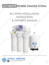
Product Introduction
The brief introduction of various parts and sample connections are presented as
follows.
Please identify and get familiar with these parts and connection points for a
smooth installation.
Power Indicator
Filtering Indicator
MRO Filter Life Indicator
CF Filter Life Indicator
Front
Top
Multiple Reverse Osmosis
Membrane Filter (MRO)
RO Faucet
Filtered Water
Tubing
Power
Kitchen Faucet
Feed Water
Adapter
Input Water
Tubing
Cold Hot
Waste Water
Tubing
Waste Water Port
Input Water Port
Filtered Water Port
Pre-sediment and Carbon
Block Filter (CF)
Filter Life Reset Indicator

Press
Press
Pull
4
Installation Tips
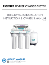
How to Use the Quick-Connect Fittings
To connect:
•Push the tubing into the tting until you reach the mark on the tubing.
NOTE: If the tubing is not fully inserted, it will cause leakage.
•When the tubing is fully inserted, put the blue lock clip on the tting. It will lock
the tubing in place and prevent it from falling off.
To disconnect:
•Remove the blue lock clip from the
tting;
•Use your thumb and index nger to
press down on the lock sleeve. Use
your other hand to pull out the tube
from the tting (Figure 2).
NOTE: Please do not pull out the
tubing directly, or else it will damage
the tting and cause leakage.
Figure 1
Figure 2
NOTE: If the tubing is too long,
cut it to a suitable length with a
sharp utility knife or scissors. Cut
the tubing squarely and cleanly
(Figure 1). Make sure the tubing
is fully inserted (about 0.8”).
Mark for
Full Insert
Cut Cleanly
and Squarely

5
Step 1: Install the Feed Water Adapter (3/8” or 1/2”)
NOTE: The input water tubing has been attached to the feed water adapter for
easy installation.
1. Shut off the water supply. Turn on the kitchen faucet to release the water
pressure;
NOTE: Make sure the water has stopped running before proceeding to the
next step. Get a towel or bucket to catch water.
2. Disconnect the cold water pipe from the cold water supply valve;
3. Twist the feed water adapter onto the cold water supply valve (with its washer)
and tighten it with an adjustable wrench (Figure 3);
NOTE: If the cold water pipe is 1/2”, unscrew the two converters from the feed
water adapter rstly (Figure 4), then implement step 3.
4. Twist the cold water pipe (with its washer) onto the feed water adapter and
tighten with an adjustable wrench.
Installation Steps
NOTE:
•The RO system must be connected to the COLD water supply ONLY.
•Do not install the system in exposure to direct sunlight or harmful chemicals, nor
any place where it may be damaged.
•Do not install the system near any heat source.
•Do not install the system outdoors.
How to Drill a Hole into Your Sink or Countertop (Optional)
NOTE: Please conrm if there is an existing hole available to install the RO
faucet. If not, please drill a hole in accordance with the following steps.
It’s highly recommended to watch the YouTube video “How to Drill Faucet Holes”
for better understanding of the process. There is also a sticker for your reference to
drill the hole. Remember to wear safety glasses to protect your eyes while drilling
the faucet hole.
1. Choose a diamond core bit for granite, and a carbide drill bit for stainless steel.
Do not use a hammer drill on natural stone, glass or ceramic;
2. Glue the sticker to your sink or countertop, and drill a hole referring to the size
shown on the sticker (1⅜”);
3. Make an indent with a center punch on a stainless steel sink before drilling to
help guide the bit;
4. Be careful when drilling on a porcelain sink, as it can be easily chipped. Apply
downward pressure rmly to the bit until breaking through the surface;
5. Starting at the lowest speed, hold the drill straight with rm pressure to prevent
the bit from walking on the counter;
6. Once breaking through the surface, swirl the drill a little to apply pressure in a
circle evenly.
Prior to installation, it is highly recommended to watch the video “Waterdrop G2
undersink RO installation” on .

6
Step 2: Install the RO Faucet (Non-Air Gap Faucet)
NOTE: If there is no hole in
your kitchen sink or countertop,
you have to drill one (1⅜”)
or use the hole in the soap
dispenser. Refer to Page 5.
1. Insert the faucet spout
into the faucet body;
2. Insert the faucet stem
into the hole on the
countertop;
3. Under the sink, slip on
other parts in the order
shown in the picture
(Figure 5);
4. Insert the quick-connect
tting onto the faucet
stem fully and rmly.
Faucet Body
3/8"
Cold Water Pipe 1/2"
Cold Water Pipe
Washer
Unscrew
Unscrew
3/8'' INPUT Water
Tubing
Feed Water
Adapter
Cold Water
Supply Valve
Mounting Washer
Nut
Countertop
Faucet Spout
Quick-Connect Fitting
(and Lock Clip)
Figure 3 Figure 4
Figure 5
Faucet Stem

7
Step 3: Install the Drain Saddle
1. Choose a spot on the drainpipe that is convenient for installing the drain saddle
and drill a 1/4” hole. Be sure not to penetrate the opposite side of the pipe;
NOTE: It’s recommended to install the drain saddle on the vertical drainpipe.
2. Slip the front plate to one end of the tubing (without mark), and insert the tubing
into the drilled hole up to about 0.6” (Figure 7);
3. Fix the drain saddle with screws and install the lock clip on the tting to secure
the connection (Figure 8);
NOTE: In some areas, the waste water tubing needs to be connected to the
drainpipe through the air gap. Consumers need to purchase additional air gap
accessories.
Figure 6 Figure 7 Figure 8
Front Plate About 0.6"
5.9"
17.3"
Back Plate
Step 4: Position the RO System Housing
Check and ensure there is sufcient space under the countertop to install the
system (Figure 9).
NOTE: Make sure that there is a power outlet in the kitchen cabinet or on the wall
connected to the lower cabinet space before installation.
It is not recommended to place the housing against the cabinet, as there may be
vibrations when the system works.
14"
Figure 9

Step 5: Connect Tubing
1. Install the Input Water Tubing
•Connect the input water tubing from the feed water adapter to the “IN” input
water port;
NOTE: Make sure it is fully inserted until you reach the mark on the tubing.
NOTE: Conrm the tubing length you need and cut the tubing if it’s too long,
referring to “How to Use the Quick-Connect Fittings” on page 4.
8
2. Install the Filtered Water Tubing
•Connect the ltered water tubing from the RO faucet to the "F" ltered water
port;
NOTE: Make sure it is fully inserted until you reach the mark on the tubing.
Quick-connect
Fitting on RO
Faucet
Filtered Water Tubing
“IN” Water Port
Input Water
Tubing
Lock Clip
Lock Clip
Filtered
Water Tubing
Feed Water Adapter
Input Water Tubing
“F” Water Port
3. Install the Waste Water Tubing
•Connect the waste water tubing from the drain saddle to the "W" waste water
port;
NOTE: Make sure it is fully inserted until you reach the mark on the tubing.
Drain Saddle
Waste
Water Tubing
Lock Clip
Waste
Water Tubing “W” Water Port

9
Step 6: Start up the System
1. Turn on the cold water supply valve. Check for leaks;
2. Insert the power plug into the socket;
NOTE: If the system can’t be powered on after you insert the power plug,
check the power under the sink, as this mostly occurs when the power under
the sink is powered off. Also, check the connection between the power plug and
the power outlet, and ensure that the system has been plugged correctly into
the power outlet, as this may occur in a few cases. To test if there is a problem
with the system itself, just pick up the system and try another power outlet.
Please contact us if the system can’t be powered on. We will help you gure it
out.
NOTE: The system will beep. The lter life indicators will ash blue, purple and
red in turn and then stay on blue for 3 seconds (Figure 10).
3. Turn on the faucet to let water run for 30 minutes until the ltering indicator on
the front panel changes from ashing to permanent blue;
NOTE: Be sure to carefully check the tightness of each part of the system
while ushing. Check and ensure all tubing is installed correctly and completely.
Make sure there is no leaking at joints, ttings, valves and tubing connections.
NOTE: The water is undrinkable during ushing for consecutive 30 minutes. If
the system stops ushing in advance, it will continue ushing when you turn on
the RO faucet again, until reaching 30 minutes.
4. Conrm the 30-minute ushing is completed before turning off the RO faucet.
Make sure the faucet does not leak.
Figure 10

10
Figure 11 Figure 12
Owner’s Manual
Display and Operation
Section 1: Working Mode Display
When making water, the lter and power indicators are permanent blue (Figure
11). Filter life indicators display in real time and their color depends on their life
span. Filtering indicator is off when the system stops making water, and the rest of
the indicators are still on (Figure 12).
Section 2: Filter Life Reminder
Pre-sediment and Carbon Block Filter (CF)
Multiple Reverse Osmosis Membrane Filter (MRO)
NOTE: Filter life may vary depending on source water quality and water usage.
Please replace the lter according to the reminder of the lter life indicators.

11
Display Status:
Status Status
Replace Soon
Replace Now
GoodNormal
Pre-warning
Warning
≤15
≤ 0
≤40
≤ 0
>15 >40 Blue
Purple
Red
N/A
Beeps 2 times when
dispensing water
Keeps beeping when
dispensing water
Indication
Light Buzzer
Remaining
Life (Day) Remaining Capacity (G)
NOTE: The indicators will notify you according to the usage time or processing
capacity of the lters, whichever comes rst.
There are helpful electronic lter indicators (CF/MRO) on the front panel that will
notify you to perform routine lter replacement by color change. Be sure to reset
the lter life indicator every time you replace your lter.
NOTE: If the lter expires, please purchase and replace the lter immediately.
Otherwise, the ltration efciency will decrease signicantly and affect the
performance.
Section 3: Filter Replacement Guide
How to Replace Filters:
The lters could be replaced directly without cutting off the power and water, and
there will be no water and electric leakage.
1. Twist the lter that needs to be replaced counterclockwise (Figure 13);
NOTE: The CF lter is relatively short. When removing the lter, it is
recommended to hold the lter with one hand, while rotating and removing
the lter with the other hand, in order to prevent the lter from falling out of the
system.
2. Remove wrappings and protective cap from the new lter;
3. Insert the lter into its corresponding hole, aligning the arrow with the empty
circle on the housing;
4. Twist the lter with a little force forward in a clockwise direction for 90 degrees,
until the arrow is aligned with the solid circle on the housing. You may hear a
click when the lter is tted into the place properly;
NOTE: Repeat the above steps to install the other lter.
5. Reset the lter life indicator and ush the lter after replacement (please refer
to the following steps).
Good Replace Soon Replace Now

12
How to Reset the Filter Life Indicator:
1. Press the lter life reset indicator for 5 seconds (Figure 14). Release the indicator
when you hear a beep. Now lters are ready to be reset;
2. Press the reset indicator and choose the CF lter or MRO lter (there is no
need to choose if only one lter expired). The lter life indicator will ash when
it is selected;
3. Press the reset indicator for 5 seconds again. The reset is completed when you
hear a beep. The lter life indicator will be permanent blue.
NOTE: When the lter life indicator starts ashing, the system will stop resetting if
there is no operation in 10 seconds.
Figure 13
Figure 14
MRO Filter Life Indicator
CF Filter Life Indicator
Filter Life Reset Indicator

13
How to Flush the Filter After Replacement:
For the CF lter: Turn on the RO faucet to ush for 5 minutes;
For the MRO lter: Turn on the RO faucet to ush for 30 minutes.
NOTE: If you replace the CF lter and MRO lter at the same time, turn on the
faucet to ush for 30 minutes. The ltering indicator is ashing during ushing. You
can stop ushing until the ltering indicator changes from ashing to permanent
blue.
Section 4: Malfunction Display
Overworked Reminder:
When the system continuously makes water for more than 30 minutes, the
overworked reminder will be executed and the buzzer will beep for 3 minutes. The
system stops making water when working for over 33 minutes, and the ltering
indicator and power indicator are off. Meanwhile, the CF and MRO lter life
indicators ash red. The system needs to be powered on again to recover itself.
Starting and Stopping Frequently Reminder:
The RO system will perform a starting and stopping frequently reminder when the
booster pump is frequently started and stopped in 20 minutes. The system will
stop making water, while the ltering indicator and power indicator are off and the
CF and MRO lter life indicators ash purple. The system needs to be powered on
again to recover itself.
System Maintenance
•If you do not use the machine for a long time (more than 1 week), it is
recommended to turn on the faucet to ush for a while before using it again;
•Please replace the lter regularly according to the lter life indicator;
NOTE: While the testing was performed under standard laboratory conditions,
actual performance may vary depending on the source water quality and
water usage. In case of a premature blockage and failure of the lters, it’s
recommended to replace the lter in accordance with actual usage.
•Clean the system with clear water. Do not spray the water directly onto the lter.
Do not use steel wool, an abrasive cleaner or a corrosive liquid such as gasoline
or acetone;
•When cleaning, do not pour other liquids into the lter or you risk damaging the
lter system;
•Keep the waste water pipe unobstructed to avoid damage to the lter or internal
components;
•When the drainpipe is blocked, do not use the system (please turn off the
power) to avoid the waste water from soaking the oor;
•Check the system and water pipe ttings regularly for water leakage to avoid
any property damage;
•Regularly check whether the power supply and wires are damaged or loose to
avoid major accidents caused by electric leakage.
•If you are using well water as the source, please ensure that the feed water has
been through a pre-ltration system. Otherwise, large particles in the well water
will easily clog the lter and shorten the lter life.

14
•If the System Cannot Be Powered on After You Insert the Power
Plug
a. Check the power under the sink, as this mostly occurs when the power under
the sink is powered off. Also, check the connection between the power plug and
the power outlet, and ensure that the system has been plugged correctly into
the power outlet, as this may occur in a few cases.
To test if there is a problem with the system itself, just pick up the system and
try another power outlet. Please contact us if the system can’t be powered on.
We will help you gure it out.
• No Output Water from RO Faucet
a. Filter expires: Check the lter life indicators to conrm which lter needs to be
replaced and replace it immediately.
b. Low water pressure: Check and conrm the water pressure is between 14.5 psi and
87 psi.
c. Water supply is off: Turn on the feed water adapter or water supply valve.
d. Incorrect lter installation: Reinstall the two lters, make sure they are tted into
properly.
e. A tubing is crimped: Check all tubings and remove any crimps.
• Low Water Flow at RO Faucet
a. A tubing is crimped or there’s a leak from the tubing connection: Check to
ensure all tubing is installed correctly and completely.
b. Filter expires: Check the lter life indicators to conrm which lter needs to be
replaced and replace it immediately.
c. Low water temperature: Be sure to use the system in a temperature of 41-100 °F.
d. Use well water as the source and the feed water has not been through a pre-
ltration system, the lter has been clogged. If you are using well water as the
source, please ensure that the feed water has been through a pre-ltration
system. Otherwise, large particles in the well water will easily clog the lter and
shorten the lter life.
Troubleshooting
•High TDS in Filtered Water
The system will provide a 90%+ TDS rejection rate (tested under standard
laboratory conditions) when working properly. If the TDS reading is high, the
following are possible causes:
a. The system hasn’t been used for a long time. Turn on the RO faucet, and allow
water to run for a while. The TDS reading will return to normal.
b. The RO membrane lter expires: Replace the RO membrane lter immediately.
c. The waste water tubing may be crimped or clogged: Check and remove crimps.
Realign the drain saddle and drainpipe.
d. The source water may have a high TDS: Test the source water and ltered
water. The ltered water’s TDS should be about 5%-10% of your source water’s
TDS. This is a normal range. If there is a high TDS in the source water, it may
reduce the service life of the system. When the ltered water’s TDS creeps up to
15%-20% of the source water’s TDS, please perform routine lter replacement.

15
•Booster Pump Overworked Reminder
Buzzer keeps beeping for 3 minutes and then the lter life indicators on the front
panel ash red.
a. Continuously dispensing water for more than 30 minutes: Power on the system
again to recover.
b. There is a leak at the tubing connection between the system and RO faucet:
Turn off the power. Check the tubing connection, make sure the tubing is
inserted into the quick-connect tting properly and rmly, and power on the
system again.
•Booster Pump Starting and Stopping Frequently Reminder
Buzzer beeps 5 times and then the lter life indicators on the front panel ash
purple. There is an internal pressure imbalance: Disconnect the power. Turn on or
turn off the RO faucet completely, remove all tubing crimps. Make sure the faucet is
not blocked and power on the system again.
•Loud Sound from the RO System
The sound will not exceed 55 dB, which makes no difference to everyday life (55
dB is tested under standard laboratory conditions, and the feed water pressure
is between 14.5 psi and 87 psi). A loud sound may be caused by the following
reasons:
a. The system is not positioned in a at area. Make sure the system is placed
smoothly without shaking.
b. The system is placed against the cabinet. Do not place the system against the
cabinet. The system may vibrate when it works.
c. The water pressure is instable. Check and conrm the water pressure is
between 14.5 psi and 87 psi. The sound will decrease when the water pressure
becomes stable.
•Filtered Water from the RO Faucet Tastes Like Tap Water
a. Incorrect tubing installation: Make sure the waste water tubing is not connected
with the RO faucet.
b. Filter expires: Check the lter life indicators to conrm which lter needs to be
replaced and replace it immediately.
• Water Leakage
a. Check all joints, ttings and tubing connections to locate the leakage. Make
sure the lters are well installed.
/