Page is loading ...

UPS Keor Compact
User manual
Item LE13289AA-11/21-01 WP
2
UK ENGLISH 3
UPS Keor Compact

UPS Keor Compact
3
Installation and maintenance manual
1 Introduction 5
1.1 Purpose of the manual 5
1.2 Symbols in the manual 5
1.3 Where and how to keep the manual 6
1.4 Update of the manual 6
1.5 Manufacturer's liability and guarantee 6
1.5.1 Guarantee terms 6
1.5.2 Extension of the guarantee and maintenance contracts 7
1.6 Copyright 7
1.7 General UPS description 8
1.7.1 UPS operating modes 9
2 Regulatory and safety requirements 10
2.1 General notes 11
2.2 Denitions of “Skilled Technician” and “Operator” 11
2.2.1 Skilled Technician 11
2.2.2 Operator 11
2.3 Personal Protective Equipment 12
2.4 Hazard signs in the workplace 12
2.5 Signs on the equipment 13
2.6 General warnings 13
2.7 How to proceed in an emergency 14
2.7.1 First-aid procedures 14
2.7.2 Fire procedures 14
3 Transportation and placement 15
Contents

4
4 Installation 15
4.1 Rear view 15
5 Operations 16
5.1 Switching on the UPS 16
5.1.1 Normal mode 17
5.1.2 Cold start 18
5.1.3 Start-up in Eco mode 18
5.1.4 Start-up in Converter mode 18
5.2 Switch to bypass 19
5.3 Front Panel 19
5.3.1 Touch screen sections 19
5.3.2 Menu pages 20
5.3.3 Parameters section 23
5.3.4 Mimic display 24
6 Maintenance 25
6.1 Preventive maintenance 25
6.2 Periodical checks 25
7 Warehousing 26
7.1 UPS 26
7.2 Batteries 26
8 Dismantling 27
8.1 Battery disposal 27
8.2 UPS dismantling 27
8.3 Electronic component dismantling 27
9 Technical data 28
Contents

UPS Keor Compact
User manual
5
1. Introduction
1.1 Purpose of the manual
The purpose of this manual is to provide the operator (see paragraph 2.2.1) with instructions for safely using the Keor
Compact UPS, also called “equipment” in the rest of the manual.
Extraordinary maintenance operations are not dealt with because they are the sole preserve of the LEGRAND Technical
Support Service.
The reading of this manual is essential but does not substitute the skill of technical personnel who must have received
adequate preliminary training.
The intended use and configurations envisaged for the equipment as shown in this manual are the only ones allowed by
the Manufacturer.
Any other use or configuration must be previously agreed with the Manufacturer in writing and, in this case, the written
agreement will be attached to the installation and user manuals.
This manual also refers to laws, directives and standards that the operator is required to be aware of and consult.
The original text of this publication, drafted in English, is the only reference for the resolution of disputes of interpretation
linked to translations into other languages.
1.2 Symbols in the manual
Some operations are shown in graphic symbols that draw the attention of the reader to the danger or the importance
they imply:
DANGER
This indication shows a danger entailing a high degree of risk that, if not avoided, will lead to death or serious injury or
considerable damage to the equipment and things around it.
WARNING
This indication shows a danger entailing a low level of risk that, if not avoided, could lead to minor or moderate injury or
material damage to the equipment and the things around it.
CAUTION
This indication shows a danger entailing a low level of risk that, if not avoided, could lead to minor or moderate injury or
material damage to the equipment and the things around it.
INDICATION
This symbol indicates important information which should be read carefully.

6
1.3 Where and how to keep the manual
This manual must be kept in a safe, dry place and must always be available for consultation.
It is recommended to make a copy of it and file it away.
If information is exchanged with the Manufacturer or the authorized assistance personnel, it is essential to refer to the
equipment’s rating plate data and serial number.
INDICATION
The manuals provided with the equipment are an integral part of it and must therefore be kept for its entire lifetime. In case
of need (for example in case of damage that even partially compromises its consultation) a new copy must be requested
from the Manufacturer, quoting the publication code on the cover.
1.4 Update of the manual
The manual reflects the state of the art when the equipment was put onto the market. The publication conforms to the
directives current on that date. The manual cannot be considered inadequate when new standards come into force or
modifications are made to the equipment.
Any addition to the manual the Manufacturer considers appropriate to send to the users, must be kept together with the
manual of which they will become an integral part.
The version of the manual updated to its latest release is available on the Internet at http://www.ups.legrand.com
1.5 Manufacturer’s liability and guarantee
The skilled technician and the operator shall scrupulously comply with the precautions and installation instructions
indicated in the manuals. They must:
- always work within the operating limits of the equipment;
- always carry out constant and careful maintenance through a skilled technician who complies with all the procedures
indicated in the installation and maintenance manual.
The Manufacturer declines all indirect or direct responsibility arising from:
- assembly and cabling made by personnel not fully qualified according to national standards to work on equipment
presenting electrical hazards;
- assembly and cabling made without using safety equipment and tools required by national safety standards;
- failure to observe the installation and maintenance instructions and use of the equipment which differs from the
specifications in the manuals;
- use by personnel who have not read and thoroughly understood the content of the user manual;
- use that does not comply with the specific standards used in the country where the equipment is installed;
- modifications made to the equipment, software, functioning logic unless they have been authorized by the Manufacturer
in writing;
- repairs that have not been authorized by the LEGRAND Technical Support Service;
- damage caused intentionally, through negligence, by acts of God, natural phenomena, fire or liquid infiltration;
- damage caused using batteries and protections not specified in the manuals;
- accidents caused by a wrong assembly of the safety protections or due to the lack of application of the safety labels
specified in the installation manual.
The transfer of the equipment to others also requires to hand over all the manuals. Failure to do it will automatically nullify
any right of the buyer, including the terms of the guarantee where applicable.
If the equipment is sold to a third party in a country where a different language is spoken, the original owner shall be
responsible for providing a faithful translation of this manual in the language of the country where the equipment will
be used.
1.5.1 Guarantee terms
The guarantee terms may vary depending on the country where the UPS is sold. Check the validity and duration with
LEGRAND’s local sale representative.
If there should be a fault in the product, contact the LEGRAND Technical Support Service which will provide all the
instructions on what to do.
Do not send anything back without LEGRAND’s prior authorization.
1. Introduction

UPS Keor Compact
User manual
7
The guarantee becomes void if the UPS has not been brought into service by a properly trained skilled technician (see
paragraph 2.2.1).
If during the guarantee period the UPS does not conform to the characteristics and performance laid down in this manual,
LEGRAND at its discretion will repair or replace the UPS and relative parts.
All the repaired or replaced parts will remain LEGRAND’s property.
LEGRAND is not responsible for costs such as:
- losses of profits or earnings;
- losses of equipment, data or software;
- claims by third parties;
- any damage to persons or things due to improper use, unauthorized technical alterations or modifications;
- any damage to persons or things due to installations where the full compliance with the standard regulating the specific
usage applications have not been guaranteed.
1.5.2 Extension of the guarantee and maintenance contracts
The standard guarantee can be consolidated in a single extension contract (maintenance contract).
Once the guarantee period has passed, LEGRAND is available for giving a technical assistance service able to meet all
requirements, maintenance agreements, 24/7 availability and monitoring.
Please, contact the LEGRAND Technical Support Service for further information.
1.6 Copyright
The information contained in this manual cannot be disclosed to any third party. Any partial or total duplication of the
manual by photocopying or other systems, including electronic scanning, which is not authorized in writing by the
Manufacturer, violates copyright conditions and may lead to prosecution.
LEGRAND reserves the copyright of this publication and prohibits its reproduction wholly or in part without previous
written authorization.
8
1.7 General UPS description
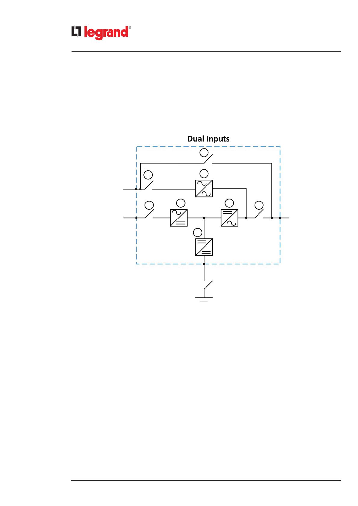
The UPS systems described in this manual are on-line, double conversion; the inverter included in the UPS always supplies
energy to the load, whether the mains is available or not (according to the battery autonomy time).
This configuration guarantees the best service to the user, as it supplies clean power uninterruptedly, ensuring voltage
and frequency stabilization at nominal value. Thanks to the double conversion, it makes the load completely immune
from micro-interruptions, from excessive mains variations, and prevents damage to critical loads.
The UPS uses IGBT technology with a high switching frequency in order to allow a low distortion of the current re-injected
into the supply line, as well as high quality and stability of output voltage. The components used assure high reliability,
very high efficiency and maintenance easiness.
• Rectifier [3]
It converts the three-phase voltage of the AC mains into continuous DC voltage using a three-phase fully controlled IGBT
bridge with a low harmonic absorption.
The control electronics uses a microprocessor of latest generation that allows to reduce the distortion of the current
absorbed by mains (THDi) to less than 5%. This ensures that the rectifier does not distort the supply mains, with regard to
the other loads. It also avoids cable overheating due to the harmonics circulation.
• Battery charger / Booster [6]
A bi-directional DC/DC converter is placed between the battery and the DC bus.
The converter has a double function. When the mains is present and the rectifier operational the converter works as
battery charger, restoring the energy lost by the battery and keeping it in floating charge. In case of mains or rectifier
failure the battery supplies energy to the inverter through the converter, which works as booster stage.
As the mains is back the rectifier provides energy to the inverter and the converter restores its function as battery charger.
• Inverter [4]
It converts the direct voltage coming from the rectifier or from the DC battery into alternating AC voltage stabilized in
amplitude and frequency.
The fully digital control of the output sinewave allows to achieve high performances, among which a very low voltage
distortion even in presence of high-distorting loads.
1. Introduction
1
2
3 4
6
Battery
Mains Input Load
x50x10
x20
x40
Bypass Input
7
5
8

UPS Keor Compact
User manual
9
• Battery
The battery can be installed inside or outside the UPS.
The battery is charged every time it has been partially or completely discharged. When its full capacity is restored, it is
kept floating to compensate for any self-discharge.
• Static bypass [5]
The static bypass allows to transfer the load between Inverter and Bypass and vice-versa, in a very short time, and uses
SCR’s as power commutation elements.
• Maintenance bypass [2]
The maintenance bypass is used to cut off the UPS completely, supplying the load directly from the input mains in case
of maintenance or serious failure
1.7.1 UPS operating modes
The UPS has four main operating modes.
• Normal operation
During normal operation all the circuit breakers/isolators are closed, except for MBP (maintenance bypass).
The rectifier is supplied by the AC three-phase input voltage, feeds the inverter and compensates mains voltage as well as
load variations, keeping the DC voltage constant. The battery charger keeps the battery charged (floating or boost charge
depending on the battery type). The inverter converts the DC voltage into an AC sinewave with stabilized voltage and
frequency and supplies the load via its static switch SSB.
• Bypass operation
The load can be switched to bypass either automatically or manually. The manual changeover can be performed by
display forcing the load to bypass. In case of failure of the bypass line, the load is switched back to inverter without
interruption.

10
• Battery operation
In case of power failure or rectifier fault, the battery feeds the inverter without interruption through the booster converter.
The battery voltage drops based on the amplitude of the discharging current. The voltage drop has no effect on the
output voltage, which is kept constant by changing the PWM modulation. An alarm is activated when the battery is near
the minimum discharge value.
In case the supply is restored before the battery is completely discharged, the system will be switched back to normal
operation automatically. In the opposite case, the inverter shuts down and the load is switched to the bypass line. If
the bypass line is not available or is out of tolerance, the loads supply is interrupted as soon as the battery reaches the
discharge limit threshold (black-out).
As soon as the supply is restored, the battery charger will recharge the battery. In the standard configuration, the loads are
supplied again via static switch SSB when mains is available again. The inverter is restarted when the battery has partially
restored its capacity.
• Maintenance mode
The maintenance bypass operation is necessary whenever the UPS functionality is tested, or during maintenance or repair
work. During this mode, the UPS is completely shut down and the load is directly supplied by the bypass line.
1. Introduction

UPS Keor Compact
User manual
11
2. Regulatory and safety requirements
DANGER
Before carrying out any operation on the equipment, it is necessary to read the entire manual carefully, especially
this chapter.
2.1 General notes
The equipment has been made for the applications given in the manual. It may not be used for purposes other than those
for which it has been designed, or differently from those specified in this manual.
The various operations must be carried out according to the criteria and the chronology described in this manual.
2.2 Definitions of “Skilled Technician” and “Operator”
2.2.1 Skilled Technician
The professional that will carry out the installation, start up and ordinary maintenance is called “Skilled Technician”.
This definition refers to people qualified by LEGRAND who have the specific technical qualification and are aware of the
method of installing, assembling, repairing, bringing online and using the equipment safely.
In addition to the requirements listed in the paragraph below for a general operator, the Skilled Technician is qualified
according to national safety standards to work under dangerous electrical voltage and uses the personal protective
equipment required by national safety standards for all the operations indicated in this manual (see the examples listed
in paragraph 2.3).
INDICATION
The safety manager is responsible for protection and company risks prevention according to what is indicated in European
directives 2007/30/EC and 89/391/EEC regarding safety in the workplace.
The safety manager must ensure that all the people working on the equipment have received all the instructions
concerning them in the manual, especially those contained in this chapter.
2.2.2 Operator
The professional assigned to the equipment for normal use is called “Operator”.
This definition refers to people who know how to operate the equipment defined in the user manual and have the fol-
lowing requisites:
- technical education, which enables them to operate according to safety standards in relation to the dangers linked to
the presence of electric current;
- training on the use of personal protective equipment and basic first aid interventions.
The company safety manager, in choosing the person (operator) who uses the equipment, must consider
- the person’s work fitness according to the laws in force;
- the physical aspect (not disabled in any way);
- the psychological aspect (mental stability, sense of responsibility);
- the educational background, training and experience;
- the knowledge of the standards, regulations and measures for accident prevention.
He shall also provide training in such a way as to provide thorough knowledge of the equipment and its component parts.
Some typical activities the operator is expected to carry out are:
- the use of the equipment in its normal functioning state and the restore of the functioning after it shuts down;
- the adoption of the necessary provisions for maintaining the quality performance of the UPS;
- the cleaning the equipment;
- cooperation with personnel responsible for ordinary maintenance activities (skilled technicians).

12
2. Regulatory and safety requirements
2.3 Personal Protective Equipment
DANGER
The UPS poses a considerable risk of electric shocks and a high short circuit current. During installation, use and
maintenance operations, the equipment mentioned in this section must be used.
People responsible for operating this equipment and/or passing close to it must not wear garments with flowing sleeves,
nor may laces, belts, bracelets or other metal pieces that might cause a danger.
The following list sum up the minimum Personal Protective Equipment to wear always.
Additional requirements may be needed according to national safety standards.
Anti-accident and no-spark shoes
with rubber sole and reinforced toe
Protective gloves for handling operations
Isolated rubber gloves for operations of connection
and work under hazardous voltage
PProtective garments for electrical work
Protective face and head shield
Isolated tools
INDICATION
The skilled technician must work on electrical insulated carpet and he must not wear any kind of metal objects like
watches, bracelets, etc.
2.4 Hazard signs in the workplace
The following signs must be exhibited at all points of access to the room where the equipment is installed:
Electric current
This sign indicates the electrical live parts.
How to proceed in an emergency
Do not use water to quench res but just the extinguishers specially designed for putting out res in electrical
equipment.
No smoking
This sign This sign indicates that smoking is not allowed.

UPS Keor Compact
User manual
13
2.5 Signs on the equipment
Displayed on the UPS are explanatory plates that can vary depending on the country the equipment is intended for and
constructional standards applied.
Make sure the instructions are adhered to. Removing these plates and working in a way that differs from what written
there, is strictly prohibited.
The plates must always be clearly read, and they must be cleaned periodically.
If a plate deteriorates and/or it is no longer legible, even partially, the Manufacturer must be contacted for another one.
CAUTION
The plates must not be removed or covered. No other plates may be affixed to the equipment without the Manufacturer’s
prior written authorisation
WARNING
Potential risks can be drastically reduced by wearing the Personal Protective Equipment listed in this chapter, which are
indispensable. Always operate with due care around dangerous areas marked by the appropriate warning notices on the
equipment.
2.6 General warnings
DANGER
The UPS works with dangerous voltages. Only skilled technicians qualified and authorized by LEGRAND must perform the
installation and ordinary maintenance operations. No part of the UPS can be repaired by the operator.
Extraordinary maintenance operations must be carried out by LEGRAND Technical Support Service personnel.
DANGER
Before beginning any installation and/or maintenance operation, make sure that all the DC and AC power sources are
disconnected.
The UPS and the external battery cabinet, if present, must be installed with an earth connection to avoid high leakage
currents. First connect the earthing cable.
Check during each installation and/or maintenance operation the continuity of the earthing system.
DANGER
The UPS is powered by its own DC energy source (batteries). The output terminals may have a dangerous voltage even if
the UPS is not connected to the AC power network.
Disconnect all batteries before performing any installation and/or maintenance operation
WARNING
A battery can present a risk of electrical shock and burns by high short-circuit circuit current. Failed batteries can reach
temperatures that exceed the burn thresholds for touchable surfaces. The following precautions should be observed
when working on batteries:
a) remove watches, rings or other metal objects.
b) use tools with insulated handles.
c) wear rubber gloves and boots.
d) do not lay tools or metal parts on top of batteries.
e) disconnect the charging source prior to connecting or disconnecting battery terminals.
f) determine if battery is inadvertently grounded. If inadvertently grounded, remove source from ground.
Contact with any part of a grounded battery can result in electrical shock. The likelihood of such shock can be reduced if
such grounds are removed during installation and maintenance (applicable to equipment and remote battery supplies
not having a grounded supply circuit).
g) never leave live cable terminals without an insulated protection.
h) When replacing batteries, replace with the same type and number of batteries or battery packs. There
is the risk of explosion if batteries are replaced by an incorrect type.
Do not dispose of batteries in a fire. The batteries may explode.
Do not open or mutilate batteries. Released electrolyte is harmful to the skin and eyes. It may be toxic. The batteries
installed inside the cabinet must be disposed of correctly. For the disposal requirements refer to local laws and relevant
standards.
14
INDICATION
The UPS functions with TT, TN-C and TN-S systems. Input/Bypass and output neutral are not referenced to the same
neutral potential.
For TN-C systems, it is necessary to bridge together the input, bypass and output neutral on the terminals during the
installation.
CAUTION
Do not open the battery breakers while the UPS is powering the loads in battery mode.
WARNING
To reduce the risk of fire or electric shock, the UPS must work in closed, clean environments with controlled temperature
and humidity. It must be kept away from inflammable liquids and corrosive substances. The room temperature must not
be above +40°C (+104°F) and the relative humidity must be a maximum of 95% not condensing.
CAUTION
Keor Compact 10 kVA is a category C2 UPS product. In a residential environment, this product may cause radio interference,
in which case the user may be required to take additional measures.
All the other models of Keor Compact are products for commercial and industrial application in the second environment
- installation restrictions or additional measures may be needed to prevent disturbances.
CAUTION
- The equipment must be maintained and used according to the instructions of this manual.
- The departmental manager must instruct the operating and maintenance personnel on the safe use and maintenance of the
equipment.
- Only specifically trained, highly skilled personnel are allowed access to the equipment in order to perform maintenance.
While the maintenance operation is being carried out, signs saying “Maintenance work in progress” must be affixed in the
department in such a way that they can be easily seen from any access area.
- Any intervention on the equipment must be done only after it has been disconnected from the power supply network by
means of a switch disconnector and must be locked with an appropriate padlock.
- The UPS must not be turned on if liquid is leaking from the batteries.
- The equipment used for any maintenance operations (pliers, screwdrivers etc.) must be electrically insulated.
- Depositing flammable material near the equipment is strictly forbidden. The equipment should always be locked, and only
specifically trained personnel are allowed access to it.
- Do not disable any safety, notification or warning device and do not ignore any alarm, warning message or notice, no matter
whether they are generated automatically or represented by plates fixed to the equipment.
- Do not run the equipment with fixed protections not installed (panels etc.).
- In case of breaking, buckling or malfunctioning of the equipment or parts of it, repair or replace immediately.
- For no reason can the structure of the equipment, the devices mounted on it, the operation sequence etc., be modified,
manipulated or tampered with in any way, without prior consultation with the Manufacturer.
- When replacing fuses, only use ones of the same type.
- The replacement of the batteries is an operation intended to be carried out by a skilled technician.
- Keep a register in which to enter the date, time, type, performer’s name and any other useful information about each and any
routine and extraordinary maintenance operation.
- Do not use oils or chemical products for cleaning because they could scratch, corrode or damage certain parts of the equipment.
- The equipment and workplace must be kept completely clean.
- Upon completion of the maintenance operations, before connecting the power supply, carefully check that no tools and/or
material of any kind have been left next to the equipment.
2.7 How to proceed in an emergency
The following information are general.
For the specific interventions consult the regulations in force in the country where the equipment is installed.
2.7.1 First-aid procedures
When administering first aid, adhere to the company rules and the usual procedures.
2.7.2 Fire procedures
Do not use water to quench fires but just the extinguishers specially designed for putting out fires on electrical equipment.
2. Regulatory and safety requirements
UPS Keor Compact
User manual
15
3. Transportation and placement
Refer to the installation manual.
DANGER
All UPS installation operations must be carried out exclusively by a SKILLED TECHNICIAN (paragraph 2.2.1) and he
will follow the instructions in the installation manual.
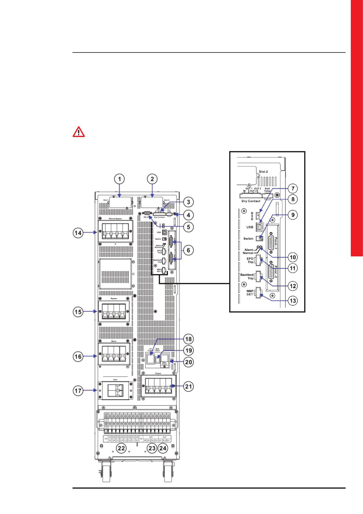
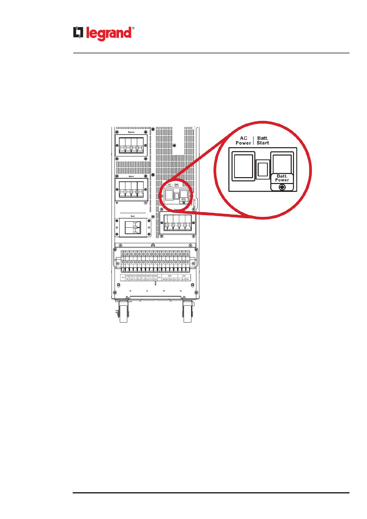
4.1 Rear View
4. Installation
1. Communication Slot 1
2. Communication Slot 2
3. Dry Contacts
4. External Battery Temperature Connector
5. RS-232 Port for Setting Software
6. Parallel Communication Ports (Option)
7. Communication Selector for Service Only
8. USB Port for Service Only
9. Terminal Resistor Setting Switch for
Parallel Communication
10. Status LED Indictors
11. EPO
12. Backfeed Protection
13. MBP Detector
14. Manual Bypass Breaker
15. Bypass Input Breaker
16. Mains Input Breaker
17. Battery Breaker
18. AC Working Power
19. Batt. Start
20. Batt. Working Power
21. Output Breaker
22. X10/X40: Mains/Bypass Input Connections Terminal
(1N, 2N, 1L3, 2L3, 1L2, 2L2, 1L1, 2L1)
23. X50: Output Connection Terminals (3N, 3L3, 3L2, 3L1)
24. X20: External Battery Connection Terminals (B-, B_N, B+)
16
5.1 Switching on the UPS
• AC Power
This is the auxiliary power switch needed to turn ON the UPS in normal mode.
Do not turn OFF the switch while the UPS is working.
• Batt. Start
This button is needed only for the cold start-up (see paragraph 5.2.2).
• Batt. Power
This switch is needed only for the cold start-up (see paragraph 5.2.2).
5. Operations

UPS Keor Compact
User manual
17
5.1.1 Normal mode
1- In the rear of UPS, turn ON the AC Power switch.
2- Close the UPS Mains Input and Bypass Input Switches.
3- Check that the parameters in the configuration setting of the UPS correspond to the UPS installation (see paragraph 5.4.3)
4- Select <Home> → <Command> → <Operation> → <Normal Mode> on the LCD panel.
5- Return to the Mimic Display and wait for the start of the rectifier.
6- Close the battery breakers only after the rectifier has been turned on.
18
7- The inverter will be started and supply output voltage.
8- Close the UPS Output Switch to supply the power to the load.
5.1.2 Cold start
1- Close the battery breakers.
2- Turn ON the Batt. Power switch in the rear of UPS.
3- In the rear of UPS, push and hold down the button “Batt. Start” at least for seven seconds.
4- Select <Home> → <Command> → <Operation> → <ColdStart Precharge Ready>→ <Normal Mode> on the LCD
panel.
If you want switch to normal mode operation, apply the procedure of the previous paragraph.
Once the UPS is working in normal mode, turn OFF the Batt. Power switch in the rear of the UPS.
5.1.3 Start-up in Eco mode
This mode effectively improves the overall efficiency. Grid power is routed through the Static Switch to the load. At the
same time, grid power continues to charge the battery in DC/DC mode through the rectifier. The Inverter is also kept
ready to switch power supply modes at any time.
Select <Home> → <Command> → <Operation> → <Eco mode> on the LCD panel.
5.1.4 Start-up in Converter mode
Converter mode allows the user to provide a power supply with constant voltage and constant frequency based on
their power requirements. The frequency can be set to 50Hz or 60Hz. The voltage options are 380/220V, 400/230V and
415/240V. These can be fine-tuned by ±8V.
Select <Home> → <Command> → <Operation> → <Converter mode> on the LCD panel.
5. Operations

UPS Keor Compact
User manual
19
5.2 Switch to bypass
During the normal mode operation of the UPS, select <Home> → <Command> → <Operation> → <Load on Bypass>
on the LCD panel.
The inverter will be shutdown and the bypass line will supply power to the load.
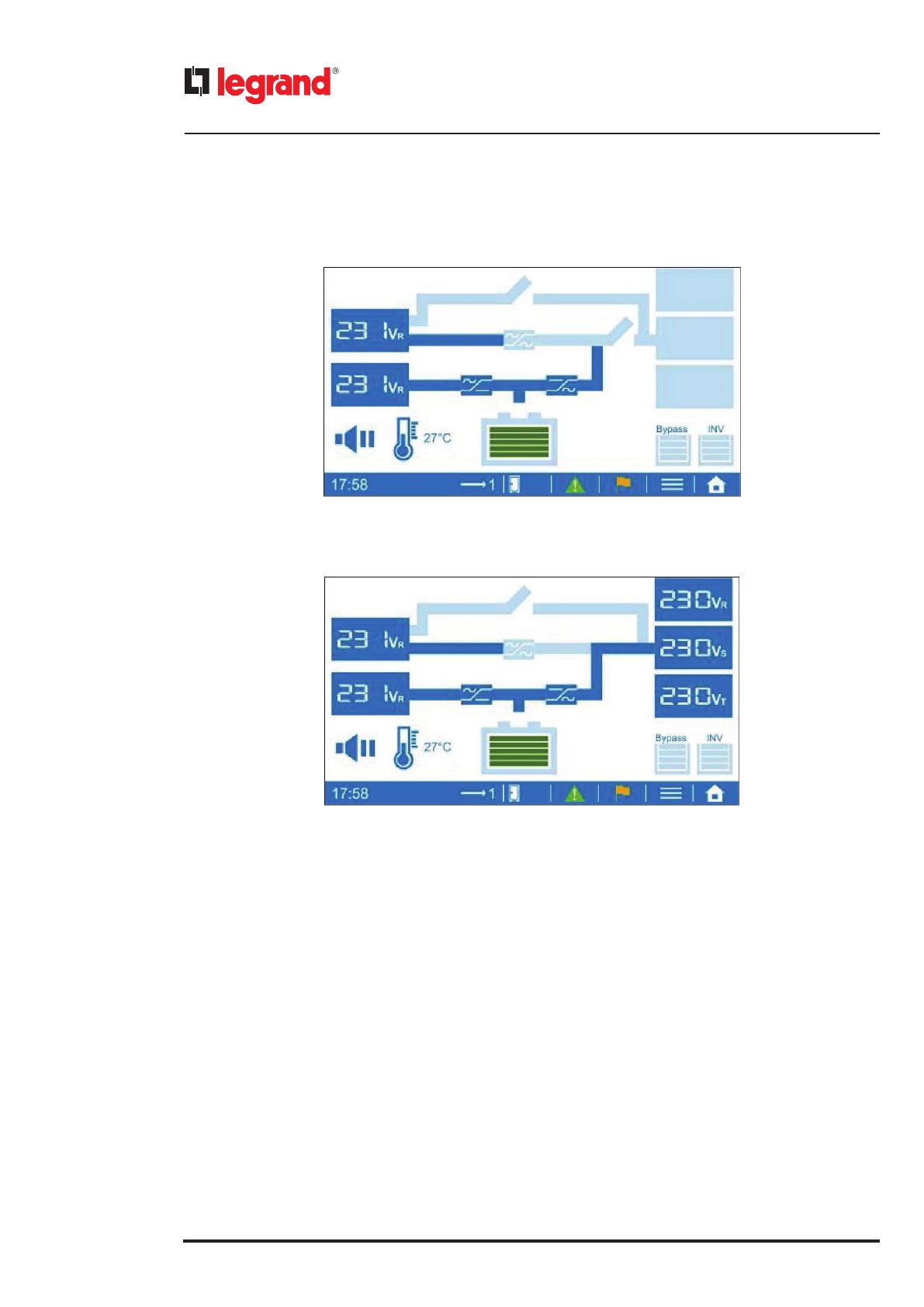
5.3 Front Panel
The UPS is equipped with an LCD touch screen which provides a simple and intuitive user interface. The touch screen is
organized with a home page, through which it is possible to access all the main sections, and with a mimic diagram which
shows the energy flow and the main input/output operating parameters.
5.3.1 Touch screen sections
The bottom part of the touch screen contains tap-sensible areas which lead to different sections of the UPS monitoring
interface.
[A] Display the current time and the status of the UPS
[B] Indicate Single or Parallel system, and select the desired UPS unit to check the information
Single unit
Parallel system
[C] Shows the alarm messages
The green icon indicates that no alarm is present
The red icon indicates the presence of alarms
[D] Shows the UPS status
[E] Enters the Sub-Menu, if available in that specific page
[F] Opens the Menu page (Home)
20
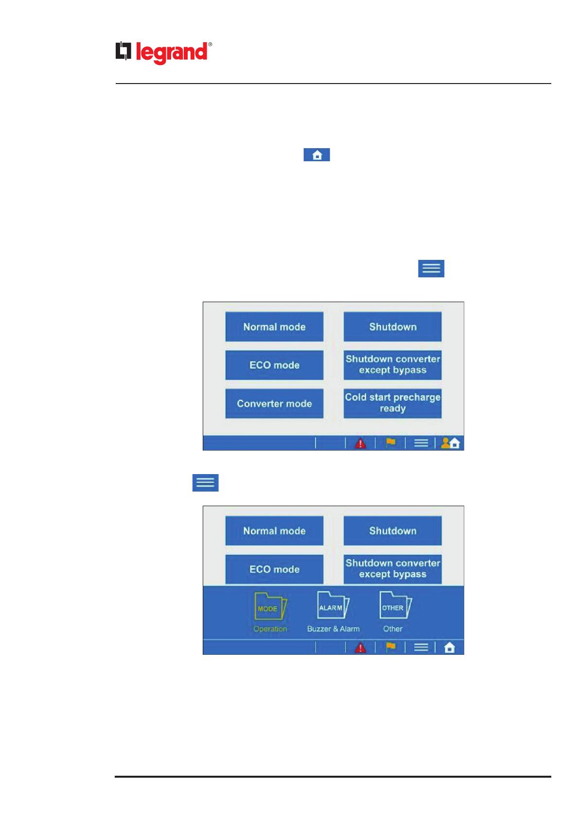
5.3.2 Menu pages
The Menu page can be opened by tapping the icon .
The pages can be changed by sliding on the screen until the required section is shown.
The sections available are:
- Mimic Display;
- Command;
- Monitor;
- Configuration;
- Management;
- Setting;
- Event Log;
- Permission Setting.
Each menu also contains sub-sections, which can be accessed by pressing the icon .
When entering the Command menu, the following page is shown:
By pressing the icon , the sub-sections can be shown or hidden.
5. Operations
/