Page is loading ...

Part. LE11506AA-03/19-01 GF
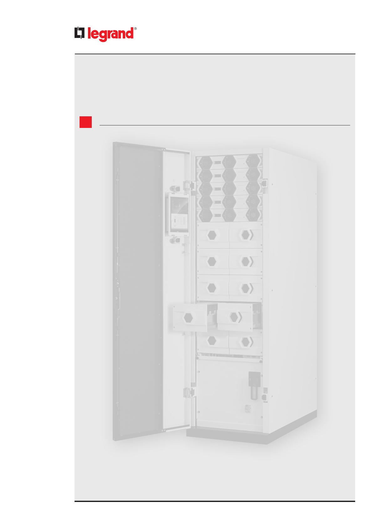
Keor MOD
User Manual
2
EN
ENGLISH 3
Keor MOD

3
User Manual
Keor MOD
1 Introduction 5
1.1 Overview 5
1.2 Purpose of the manual 5
1.3 Symbols in the manual 5
1.4 Where and how to keep the manual 6
1.5 Update of the manual 6
1.6 Manufacturer’s liability and guarantee 6
1.6.1 Guarantee terms 6
1.6.2 Extension of the guarantee and maintenance contracts 7
1.7 Copyright 7
2. Safety regulations 8
2.1 General notes 8
2.2 Denitions of “Skilled Technician” and “Operator” 8
2.2.1 Skilled Technician 8
2.2.2 Operator 8
2.3 Personal Protective Equipment 8
2.4 Hazard signs in the workplace 9
2.5 Signs on the equipment 9
2.6 General warnings 10
2.7 How to proceed in an emergency 11
2.7.1 First-aid procedures 11
2.7.2 Fire procedures 11
3. Unpacking and moving 12
3.1 Visual check 12
3.2 Equipment check 12
3.3 Unpacking 13
3.4 Movement 14
3.5 Positioning constraints 15
4. Control panel 16
4.1 Synoptic area 18
4.1.1 Input line 19
4.1.2 Rectier 20
4.1.3 Charger - Booster 20
4.1.4 Batteries 21
4.1.5 Inverter 21
4.1.6 Bypass 22
4.2 System area 23
4.3 Status bar 24
4.4 Menu bar 25
Table of Contents

4
Table of Contents
5. Operations 26
5.1 Switching on the UPS 26
5.2 Setting the UPS in forced bypass mode 26
5.3 Switching o the UPS 26
6. Installation and maintenance 27
6.1 Installation 27
6.2 Preventive maintenance 27
6.3 Periodical checks 27
6.4 Ordinary maintenance 27
6.5 Extraordinary maintenance 27
7. Warehousing 28
7.1 UPS 28
7.2 Batteries 28
8. Dismantling 29
8.1 Battery disposal 29
8.2 UPS dismantling 29
8.3 Electronic component dismantling 29
9. Technical data 30

Keor MOD
User Manual
5
1. Introduction
1.1 Overview
Congratulations on your LEGRAND purchase!
Thanks to this UPS, your critical equipments will always be protected by a constant and reliable electricity supply.
LEGRAND is specialized in designing and producing UPS units. Keor MOD is unique in its kind: it is modular, redundant
and belongs to the latest generation of high power UPS units.
High reliability, low running costs and excellent electrical performance are only some of its characteristics. The high
quality standards of LEGRAND in design and production allows Keor MOD to pass the strictest quality tests.
The UPS has been designed in compliance with the existing European community directives, with the technical standards
that include their requirements and with the eco-design guidelines.
The equipment is produced at an ISO14001 certified factory.
This publication, simply defined “user manual” herein, contains all the information for the use of the Keor MOD UPS, also
referred to as “equipment” in this manual.
The contents of the user manual are intended mainly for an operator (see paragraph 2.2.2) or for people, generically
defined as “users”, who have the need and/or obligation to provide instructions or work directly on the equipment for
their assigned tasks.
These people can be the following:
- managers;
- heads of operating areas;
- department heads;
- direct private users.
1.2 Purpose of the manual
The purpose of this manual is to provide the operator with instructions for safely using the equipment after the installation
performed by a skilled technician.
Extraordinary maintenance operations are not dealt with because they are the sole preserve of the LEGRAND Technical
Support Service.
The reading of this manual is essential but does not substitute the skill of technical personnel who must have received
adequate preliminary training.
The intended use and configurations envisaged for the equipment as shown in this manual are the only ones allowed by
the Manufacturer.
Any other use or configuration must be previously agreed with the Manufacturer in writing and, in this case, the written
agreement will be attached to the installation and user manuals.
This manual also refers to laws, directives and standards that the skilled technician is required to be aware of and consult.
The original text of this publication, drafted in English, is the only reference for the resolution of disputes of interpretation
linked to translations into other languages.
1.3 Symbols in the manual
Some operations are shown in graphic symbols that draw the attention of the reader to the danger or the importance
they imply:
DANGER
This indication shows a danger entailing a high degree of risk that, if not avoided, will lead to death or serious injury or
considerable damage to the equipment and things around it.
WARNING
This indication shows a danger entailing a medium degree of risk that, if not avoided, could lead to death or serious injury
or considerable damage to the equipment and the things around it.
CAUTION
This indication shows a danger entailing a low level of risk that, if not avoided, could lead to minor or moderate injury or
material damage to the equipment and the things around it.

6
1. Introduction
INDICATION
This symbol indicates important information which should be read carefully.
1.4 Where and how to keep the manual
This manual must be kept in a safe, dry place and must always be available for consultation.
It is recommended to make a copy of it and file it away.
If information is exchanged with the Manufacturer or the authorized assistance personnel, it is essential to refer to the
equipment’s rating plate data and serial number.
INDICATION
The manuals provided with the equipment are an integral part of it and must therefore be kept for its entire lifetime. In
case of need (for example in case of damage that even partially compromises its consultation) the operator is required to
get a new copy from the Manufacturer, quoting the publication code on the cover.
1.5 Update of the manual
The manual reflects the state of the art when the equipment was put onto the market. The publication conforms to the
directives current on that date. The manual cannot be considered inadequate when new standards come into force or
modifications are made to the equipment.
Any addition to the manual the Manufacturer considers appropriate to send to the users, must be kept together with the
manual of which they will become an integral part.
The version of the manual updated to its latest release is available on the Internet at http://www.ups.legrand.com
1.6 Manufacturer’s liability and guarantee
The skilled technician and the operator shall scrupulously comply with the precautions and installation instructions
indicated in the manuals. They must:
- always work within the operating limits of the equipment;
- always carry out constant and careful maintenance through a skilled technician who complies with all the procedures
indicated in the installation and maintenance manual.
The Manufacturer declines all indirect or direct responsibility arising from:
- assembly and cabling made by personnel not fully qualified according to national standards to work on equipment
presenting electrical hazards;
- assembly and cabling made without using safety equipment and tools required by national safety standards;
- failure to observe the installation and maintenance instructions and use of the equipment which differs from the
specifications in the manuals;
- use by personnel who have not read and thoroughly understood the content of the user manual;
- use that does not comply with the specific standards used in the country where the equipment is installed;
- modifications made to the equipment, software, functioning logic unless they have been authorized by the Manufacturer
in writing;
- repairs that have not been authorized by the LEGRAND Technical Support Service;
- damage caused intentionally, through negligence, by acts of God, natural phenomena, fire or liquid infiltration;
- damage caused using batteries and protections not specified in the manuals;
- accidents caused by a wrong assembly of the safety protections or due to the lack of application of the safety labels
specified in the installation manual.
The transfer of the equipment to others also requires to hand over all the manuals. Failure to do it will automatically nullify
any right of the buyer, including the terms of the guarantee where applicable.
If the equipment is sold to a third party in a country where a different language is spoken, the original owner shall be
responsible for providing a faithful translation of this manual in the language of the country where the equipment will
be used.
1.6.1 Guarantee terms
The guarantee terms may vary depending on the country where the UPS is sold. Check the validity and duration with
LEGRAND’s local sale representative.
If there should be a fault in the product, contact the LEGRAND Technical Support Service which will provide all the
instructions on what to do.
Do not send anything back without LEGRAND’s prior authorization.

Keor MOD
User Manual
7
The guarantee becomes void if the UPS has not been brought into service by a properly trained skilled technician (see
paragraph 2.2.1).
If during the guarantee period the UPS does not conform to the characteristics and performance laid down in this manual,
LEGRAND at its discretion will repair or replace the UPS and relative parts.
All the repaired or replaced parts will remain LEGRAND’s property.
LEGRAND is not responsible for costs such as:
- losses of profits or earnings;
- losses of equipment, data or software;
- claims by third parties;
- any damage to persons or things due to improper use, unauthorized technical alterations or modifications;
- any damage to persons or things due to installations where the full compliance with the standard regulating the specific
usage applications have not been guaranteed.
1.6.2 Extension of the guarantee and maintenance contracts
The standard guarantee can be consolidated in a single extension contract (maintenance contract).
Once the guarantee period has passed, LEGRAND is available for giving a technical assistance service able to meet all
requirements, maintenance agreements, 24/7 availability and monitoring.
Please, contact the LEGRAND Technical Support Service for further information.
1.7 Copyright
The information contained in this manual cannot be disclosed to any third party. Any partial or total duplication of the
manual by photocopying or other systems, including electronic scanning, which is not authorized in writing by the
Manufacturer, violates copyright conditions and may lead to prosecution.
LEGRAND reserves the copyright of this publication and prohibits its reproduction wholly or in part without previous
written authorization.

8
2. Safety regulations
DANGER
Before carrying out any operation on the equipment, it is necessary to read the entire manual carefully, especially
this chapter.
Look after this manual carefully and consult it repeatedly during installation and maintenance by a skilled
technician.
2.1 General notes
The equipment has been made for the applications given in the manual. It may not be used for purposes other than those
for which it has been designed, or differently from those specified in this manual.
The various operations must be carried out according to the criteria and the chronology described in this manual.
2.2 Definitions of “Skilled Technician” and “Operator”
2.2.1 Skilled Technician
The figure that will carry out the installation, start up and ordinary maintenance is called “Skilled Technician”.
This definition refers to people who have the specific technical qualification and are aware of the method of installing,
assembling, repairing, bringing online and using the equipment safely.
In addition to the requirements listed in the section below for a general operator, the Skilled Technician is qualified
according to national safety standards to work under dangerous electrical voltage and uses the personal protective
equipment required by national safety standards for all the operations indicated in this manual (see the examples
listed in paragraph 2.3).
INDICATION
The safety manager is responsible for protection and company risks prevention according to what is indicated in European
directives 2007/30/EC and 89/391/EEC regarding safety in the workplace.
The safety manager must ensure that all the people working on the equipment have received all the instructions
concerning them in the manual, especially those contained in this chapter.
2.2.2 Operator
The figure assigned to the equipment for normal use is called “Operator”.
This definition refers to people who know how to operate the equipment defined in the user manual and have the
following requisites:
1. technical education, which enables them to operate according to safety standards in relation to the dangers linked to
the presence of electric current;
2. training on the use of personal protective equipment and basic first aid interventions.
The company safety manager, in choosing the person (operator) who uses the equipment, must consider
- the person’s work fitness according to the laws in force;
- the physical aspect (not disabled in any way);
- the psychological aspect (mental stability, sense of responsibility);
- the educational background, training and experience;
- the knowledge of the standards, regulations and measures for accident prevention.
He shall also provide training in such a way as to provide thorough knowledge of the equipment and its component parts.
Some typical activities the operator is expected to carry out are:
- the use of the equipment in its normal functioning state and the restore of the functioning after it shuts down;
- the adoption of the necessary provisions for maintaining the quality performance of the UPS;
- the cleaning of the equipment;
- cooperation with personnel responsible for ordinary maintenance activities (Skilled Technicians).
2.3 Personal Protective Equipment
DANGER
The UPS poses a considerable risk of electric shocks and a high short circuit current. During installation, use and
maintenance operations, the equipment mentioned in this section must be used.
People responsible for operating this equipment and/or passing close to it must not wear garments with flowing sleeves,
nor may laces, belts, bracelets or other metal pieces that might cause a danger.
Keor MOD
User Manual
9
The following list sum up the minimum Personal Protective Equipment to wear always. Additional requirements may be
needed according to national safety standards.
Anti-accident and non-sparking shoes with rubber
sole and reinforced toe
Protective gloves for handling operations
Isolated rubber gloves for operations of connection
and work under hazardous voltage
Protective garments for electrical work
Protective face and head shield
Isolated tools
INDICATION
The skilled technician must work on electrical insulated carpet and he must not wear any kind of metal objects like
watches, bracelets, etc.
2.4 Hazard signs in the workplace
The following signs must be exhibited at all points of access to the room where the equipment is installed:
Electric current
This sign indicates the electrical live parts.
How to proceed in an emergency
Do not use water to quench fires but just the extinguishers specially designed for putting out fires in electrical
equipment.
No smoking
This sign indicates that smoking is not allowed.
2.5 Signs on the equipment
Displayed on the UPS are explanatory plates that can vary depending on the country the equipment is intended for and
constructional standards applied.
Make sure the instructions are adhered to. Removing these plates and working in a way that differs from what written
there, is strictly prohibited.
The plates must always be clearly read and they must be cleaned periodically.
If a plate deteriorates and/or it is no longer legible, even partially, the Manufacturer must be contacted for another one.
CAUTION
The plates must not be removed or covered. Signs in different languages are provided along with the equipment to
replace those in English. No other plates may be affixed to the equipment without the Manufacturer’s prior written
authorisation
10
2. Safety regulations
WARNING
Potential risks can be drastically reduced by wearing the Personal Protective Equipment listed in this chapter, which are
indispensable. Always operate with due care around dangerous areas marked by the appropriate warning notices on the
equipment.
2.6 General warnings
DANGER
The UPS works with dangerous voltages. Only Skilled Technicians must perform the installation and ordinary maintenance
operations. No part of the UPS can be repaired by the operator.
Extraordinary maintenance operations must be carried out by LEGRAND Technical Support Service personnel.
DANGER
Before beginning any installation and/or maintenance operation, make sure that all the DC and AC power sources are
disconnected.
The UPS and the external battery cabinet, if present, must be installed with an earth connection to avoid high leakage
currents. First connect the earthing cable.
Check during each installation and/or maintenance operation the continuity of the earthing system.
DANGER
The UPS is powered by its own DC energy source (batteries). The output terminals may have a dangerous voltage even if
the UPS is not connected to the AC power network.
Disconnect all battery drawers and external battery cabinets before performing any installation and/or maintenance
operation.
WARNING
A battery can present a risk of electrical shock and burns by high short-circuit circuit current. Failed batteries can reach
temperatures that exceed the burn thresholds for touchable surfaces. The following precautions should be observed
when working on batteries:
a) remove watches, rings or other metal objects.
b) use tools with insulated handles.
c) wear rubber gloves and boots.
d) do not lay tools or metal parts on top of batteries.
e) disconnect the charging source prior to connecting or disconnecting battery terminals.
f) determine if battery is inadvertently grounded. If inadvertently grounded, remove source from ground.
Contact with any part of a grounded battery can result in electrical shock. The likelihood of such shock can be reduced
if such grounds are removed during installation and maintenance (applicable to equipment and remote battery
supplies not having a grounded supply circuit).
g) never leave live cable terminals without an insulated protection.
h) When replacing batteries, replace with the same type and number of batteries or battery packs. There is the risk of
explosion if batteries are replaced by an incorrect type.
Do not dispose of batteries in a fire. The batteries may explode.
Do not open or mutilate batteries. Released electrolyte is harmful to the skin and eyes. It may be toxic. The batteries
installed inside the cabinet must be disposed of correctly. For the disposal requirements refer to local laws and relevant
standards.
INDICATION
The UPS functions with TT, IT, TN-C and TN-S systems. Input and output neutral are referenced to the same neutral
potential: the output neutral status is the same as the input neutral status.
When the output load needs a different neutral status, it is necessary to place downstream of the UPS a suitably scaled
isolation transformer that must be protected in compliance with the standards in force.
CAUTION
Do not open the battery fuse holders while the UPS is powering the loads in battery mode.

Keor MOD
User Manual
11
WARNING
To reduce the risk of fire or electric shock, the UPS must work in closed, clean environments with controlled temperature
and humidity. It must be kept away from inflammable liquids and corrosive substances. The room temperature must not
be above +40°C (+104°F) and the relative humidity must be a maximum of 95% not condensing.
INDICATION
The equipment generates, uses and can radiate radio frequency energy. If it is not installed and used in accordance with
the instructions, it may cause harmful interference with radio communications.
Keor MOD is a category C3 UPS according to the standard EN62040-2
The UPS can be used in commercial and industrial environments; nevertheless, restrictions or adequate countermeasures
might be necessary to avoid radio interference.
CAUTION
- The equipment must be maintained and used according to the instructions of this manual.
- The departmental manager must instruct the operating and maintenance personnel on the safe use and maintenance
of the equipment.
- Only specifically-trained, highly skilled personnel are allowed access to the equipment in order to perform maintenance.
While the maintenance operation is being carried out, signs saying “Maintenance work in progress” must be affixed in
the department in such a way that they can be easily seen from any access area.
- The connection of the equipment (and of any accessory devices) must always be perfectly grounded to discharge short-
circuit currents and electrostatic voltages. The input voltage must correspond with the value shown on the rating plate.
Current adapters must not be used under any circumstances. Pay attention to polarity when connecting.
- Any intervention on the equipment must be done only after it has been disconnected from the power supply network
by means of a switch disconnector and must be locked with an appropriate padlock.
- The UPS must not be turned on if liquid is leaking from the batteries.
- The equipment used for any maintenance operations (pliers, screwdrivers etc.) must be electrically insulated.
- Depositing flammable material near the equipment is strictly forbidden. The equipment should always be locked, and
only specifically trained personnel are allowed access to it.
- Do not disable any safety, notification or warning device and do not ignore any alarm, warning message or notice, no
matter whether they are generated automatically or represented by plates fixed to the equipment.
- Do not run the equipment with fixed protections not installed (panels etc.).
- In case of breaking, buckling or malfunctioning of the equipment or parts of it, repair or replace immediately.
- For no reason can the structure of the equipment, the devices mounted on it, the operation sequence etc., be modified,
manipulated or tampered with in any way, without prior consultation with the Manufacturer.
- When replacing fuses, only use ones of the same type.
- The replacement of the batteries is an operation intended to be carried out by a skilled technician.
- Keep a register in which to enter the date, time, type, performer’s name and any other useful information about each
and any routine and extraordinary maintenance operation.
- Do not use oils or chemical products for cleaning because they could scratch, corrode or damage certain parts of the
equipment.
- The equipment and workplace must be kept completely clean.
- Upon completion of the maintenance operations, before connecting the power supply, carefully check that no tools
and/or material of any kind have been left next to the equipment.
INDICATION
The skilled technician must not leave at the disposal of the operator:
- the keys for opening the UPS door;
- the installation and maintenance manual.
2.7 How to proceed in an emergency
The following information are general. For the specific interventions consult the regulations in force in the country where
the equipment is installed.
2.7.1 First-aid procedures
When administering first aid, adhere to the company rules and the usual procedures.
2.7.2 Fire procedures
Do not use water to quench fires but just the extinguishers specially designed for putting out fires on electrical equipment.

12
3. Unpacking and moving
3.1 Visual check
On delivery of the UPS, carefully inspect the packaging and the equipment for any damage that might have occurred
during transport. Check there is no damage to the indicator on the outer label reading “Shock Watch”.
If there is possible or ascertained damage, immediately inform:
- the transporter;
- the LEGRAND Technical Support Service.
Check that the equipment corresponds with the items indicated in the delivery documentation.
If the UPS must be stored, follow the instructions of Chapter 7.
3.2 Equipment check
The equipment and the relative supplied accessories must be in perfect conditions.
Check that:
- the shipping data (address of the recipient, no. of packages, order no, etc.) correspond to what is contained in the
delivery documentation;
- the technical rating plate data on the label applied to the UPS correspond with the material described in the delivery
documentation;
- the documentation accompanying the equipment includes the installation and user manuals.
In case of discrepancy, immediately inform the LEGRAND Technical Support Service before commissioning the equipment.
The content of the supply is subject to thorough checking before the shipment. Nonetheless it is always advisable to
check that it is complete and in order on receiving the material.
The following list is general:
- 1 UPS (empty cabinet) with keys to close the doors;
- 1 envelope of accessories;
- user manual;
- installation and maintenance manual.
In case of defects and/or missing items, immediately inform the LEGRAND Technical Support Service before commissioning
the equipment.
INDICATION
The installation manual must be used and consulted only by skilled technicians.
INDICATION
Power modules and battery drawers to be installed must be bought separately.
Keor MOD
User Manual
13
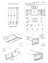
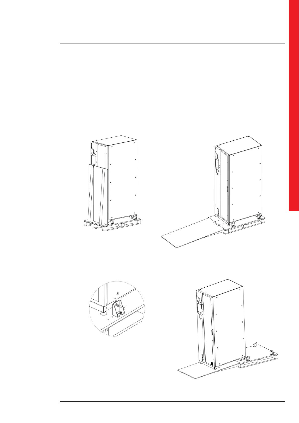
3.3 Unpacking
To remove the packaging material, comply with the following procedure:
- bring the UPS to the installation site using a forklift and/or a transpallet with suitable characteristics (see fig. 1);
- remove the plastic film and cardboards protecting the UPS;
- bring down the wooden chute attached to the pallet (see fig. 2)
- loose the screws of the brackets that fix the equipment on the pallet (see fig. 3);
- gently slide by hand the equipment along the chute using the wheels (see fig. 4).
1
3
2
4

14
3. Unpacking and moving
3.4 Movement
WARNING
Move the UPS very carefully, lifting it as little as possible and avoiding dangerous swings or falls.
Follow always the directions indicated in the symbols present on the packaging.
The equipment must always be handled by trained and instructed personnel. Comply with the safety regulations in force
in your country relative to the usage of lifting equipment and/or accessories.
The Keor MOD UPS has four wheels at the bottom of the cabinet. Before installations and while it is still empty, it can be
moved by hand by at least two people.
For any lifting, use a forklift or a transpallet with an adequate carrying capacity, placing the forks in the specific spaces of
the base and making sure they come out on the other side by at least twenty centimetres.
CAUTION
Do not move the UPS after the installation or following the insertion of the power modules.
Keor MOD
User Manual
15
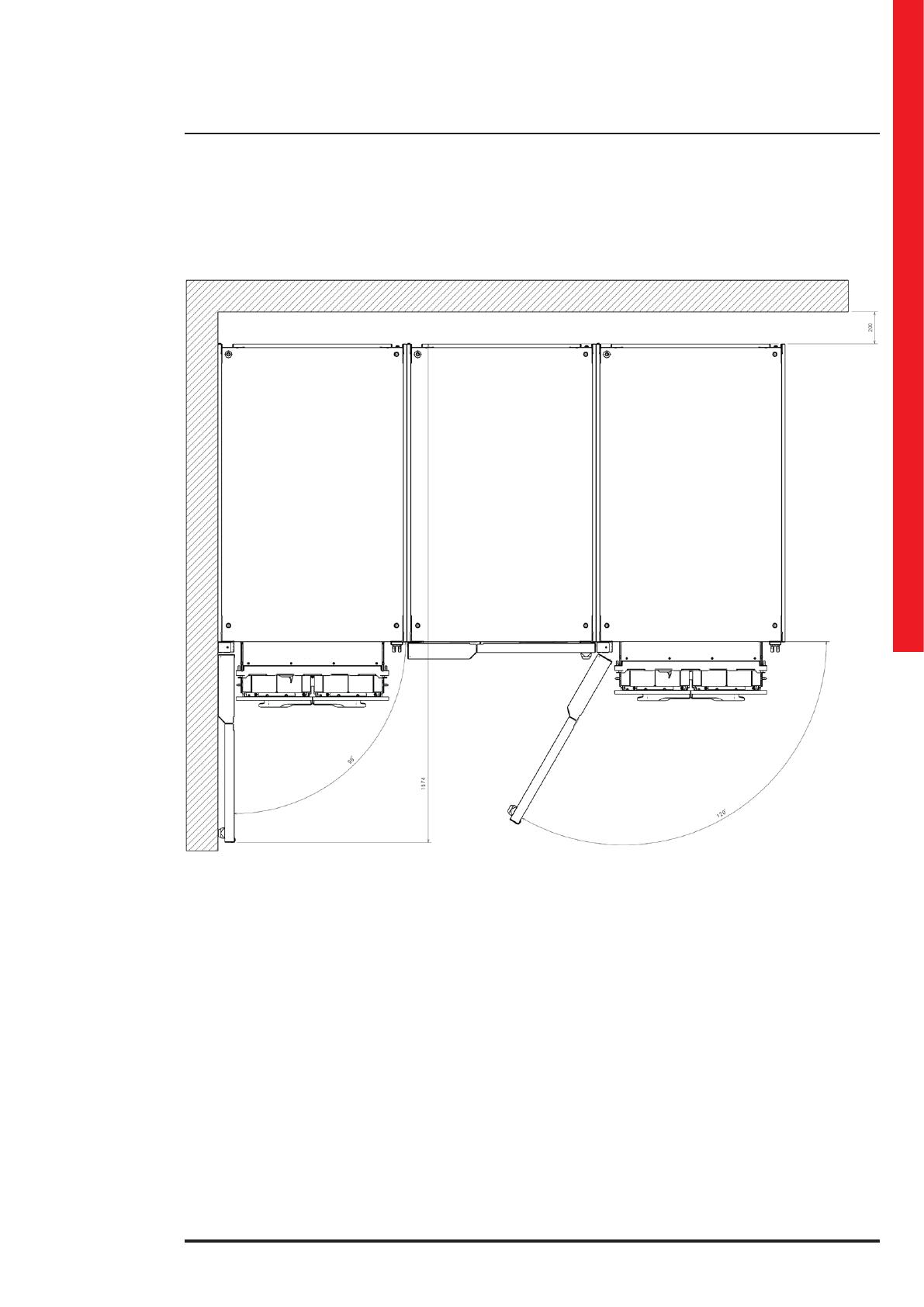
3.5 Positioning constraints
(all the dimensions are in mm)
POWER MODULE EXTRACTION
POWER MODULE EXTRACTION
BATTERY DRAWERS EXTRACTION
BATTERY DRAWERS EXTRACTION
The UPS must be positioned respecting the following conditions:
- do not cover the cooling vents of the power modules and keep a clearance of 20 cm beyond the cabinets real panels;
- keep a clearance of 160 cm on the front to allow the opening of the door;
- temperature and humidity must be within permitted limits;
- fire regulations must be respected;
- the wiring must be simply made;
- front and rear accessibility must be available for assistance or periodic servicing;
- the cooling flow of air must be guaranteed;
- the air conditioning system must be adequately sized;
- dust, corrosive and explosive atmospheres must be absent;
- the installation site must be free of vibration;
- the support surface must be sized for the weight necessary to support the equipment:
- regulate the equipment feet to have perfect perpendicularity and level of the UPS compare with the floor.
To safeguard the batteries as well as possible it is necessary to bear in mind that their average lifetime is strongly
influenced by the operating room temperature. Position the UPS in an environment with a temperature range between
+20°C (+68°F) and +25°C (+77°F) to guarantee the optimum life of the batteries.
Before proceeding with the installation operations, make sure that there is enough lighting to clearly see every detail.
Provide artificial lighting if the natural lighting does not satisfy this requirement.
In case of maintenance operations in places that are not sufficiently well lit, portable lighting systems must be used,
avoiding shadows that prevent or reduce visibility on the point where you intend to work or on the surrounding areas.
16
4. Control panel
WARNING
The control panel allows to change some functional settings of the UPS.
Only a skilled technician (paragraph 2.2.1) is authorized to modify the configuration set during the installation. Wrong
settings could lead to injury or material damage to the equipment and the things around it.
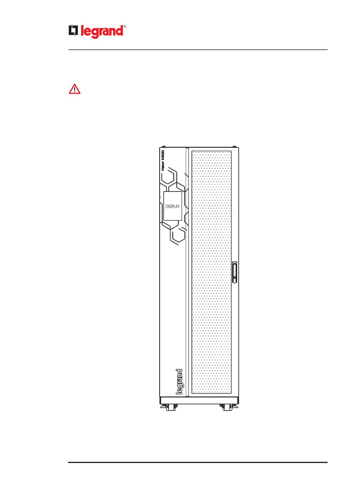
The control panel is made up of a 10’’ touch-screen colored display that is also portrait oriented. It is located on the front
door of the UPS.

Keor MOD
User Manual
17
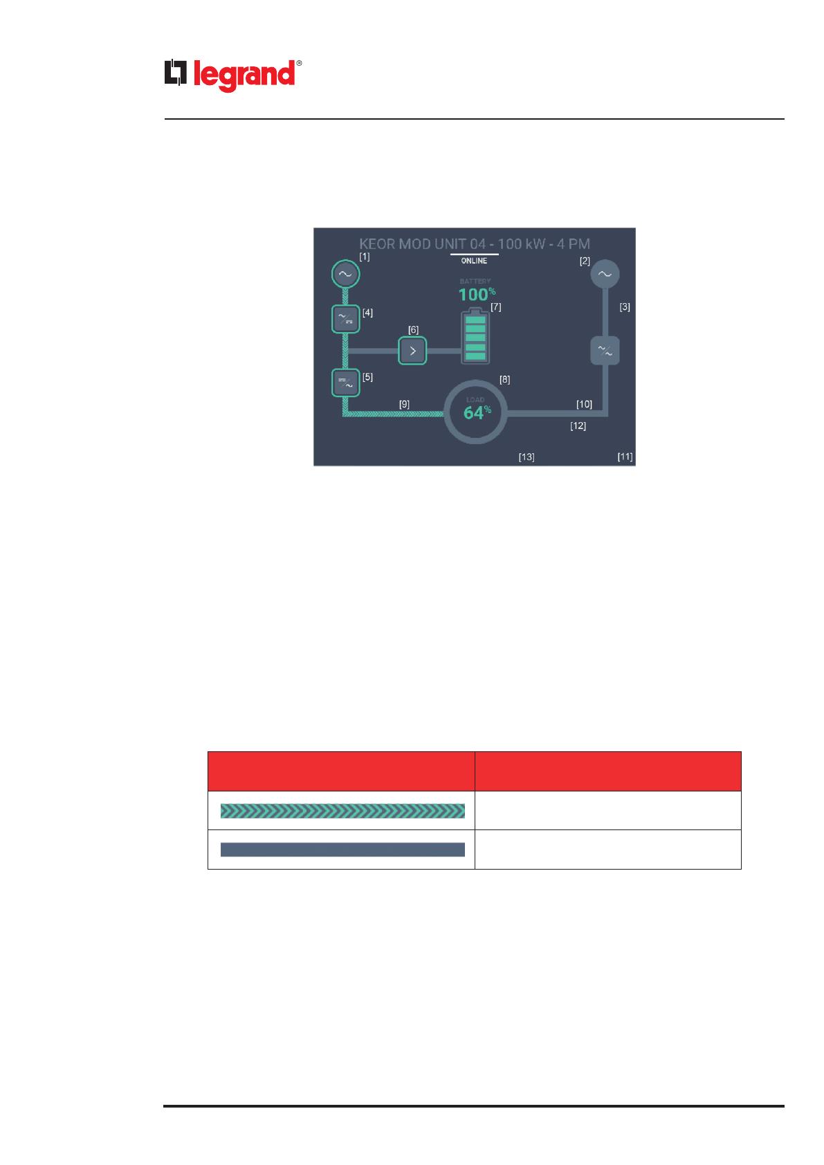
Title
Synoptic
System
Status bar
Menu bar
Each screen is made up by five parts:
- TITLE: it describes the element selected in the bottom area (SYSTEM);
• “System”: the page shows the system view;
• “UPS name”: the page shows the UPS view;
• “UPS name / Module name”: the page shows the UPS modules.
- SYNOPTIC (top area): it includes details of the element selected in the bottom area.
- SYSTEM (bottom area): it shows all the UPS that make up the system and each UPS Status Bar. The user can navigate
through the modules that build up each UPS.
- UPS STATUS BAR: it shows the status of the UPS installed on the selected cabinet.
- MENU BAR: it contains links to other sections such as the system view, service, settings, log in, traditional menu, date and
time and actions control.
18
4. Control panel
4.1 Synoptic area
The SYNOPTIC area is strictly connected to the SYSTEM area. It shows the details of what is selected in the bottom area.
The SYNOPTIC includes the following blocks:
• [1] - [2] Input
• [3] Bypass
• [4] Rectifier
• [5] Inverter
• [6] Booster-charger
• [7] Batteries
• [8] Output
• [9] Active flow
• [10] Inactive flow
• [11] Fan icon
• [12] Mute alarm icon
• [13] Temperature icon
It is possible to see which blocks are active or not by the graphical flow indication:
DESCRIPTION
Active flow
Inactive flow
Keor MOD
User Manual
19
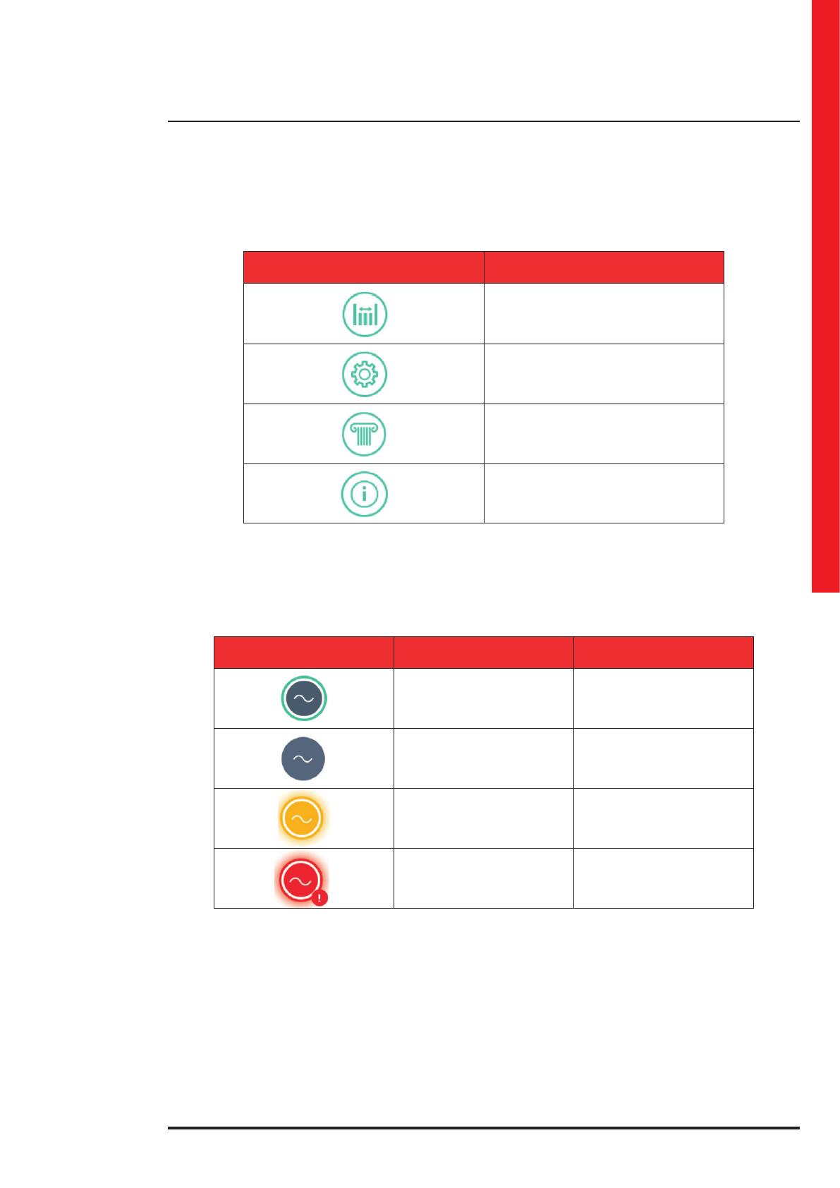
When an icon in the SYNOPTIC area is tapped, a popup window is displayed close to the icon. The popup window
contains 4 elements:
DESCRIPTION
Measurements
Settings
Historical data
Additional info
By tapping on one of these elements, a new popup window with more details is displayed in the SYSTEM area.
4.1.1 Input line
The icons regarding the input line are the following ones:
INPUT ICON COLOR DESCRIPTION
Fixed light white icon
and green stroke
The input line is present.
Normal behavior.
Fixed dark grey icon The input line is not present
Flashing light yellow icon
Some warnings of medium
gravity are occurring
Flashing light red icon
Some warnings of high
gravity are occurring
20
4. Control panel
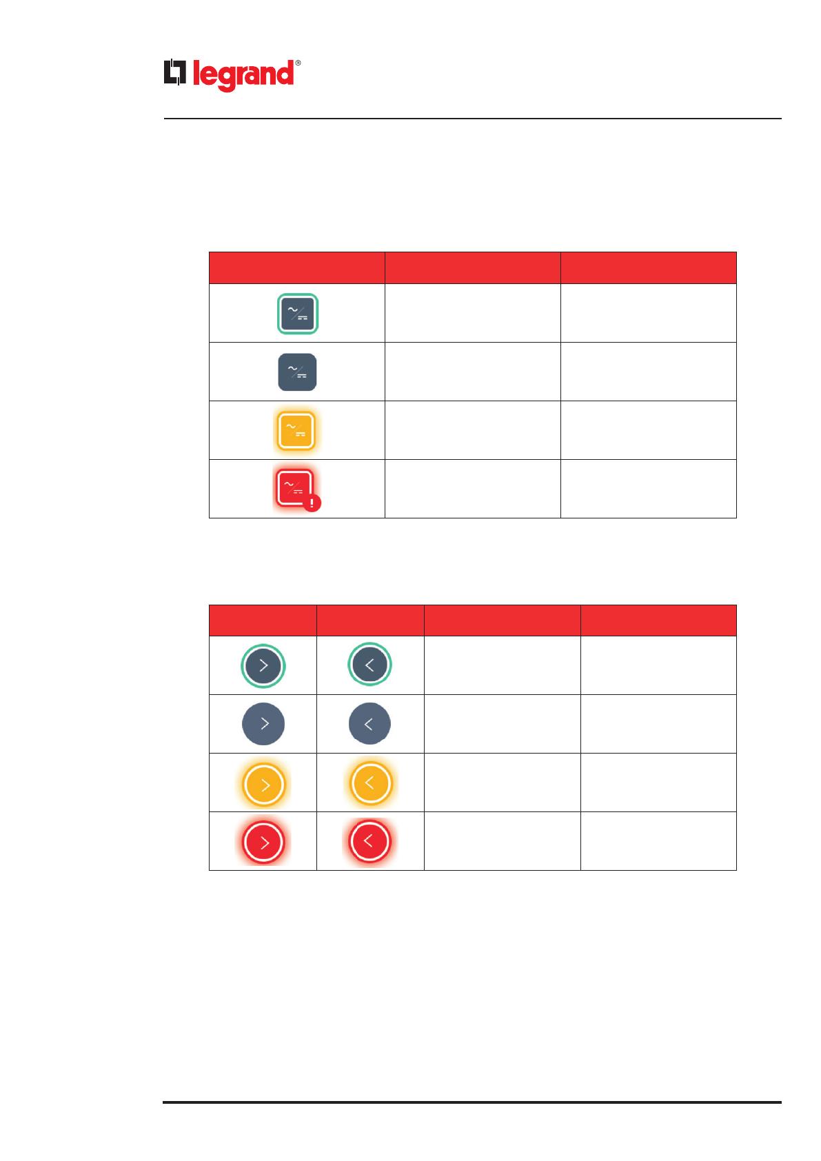
4.1.2 Rectifier
The icons regarding the rectifier are the following ones:
RECTIFIER ICON COLOR DESCRIPTION
Fixed light white icon
and green stroke
The rectifier is active.
Normal behavior.
Fixed dark grey icon The rectifier is not active
Flashing light yellow icon
Some warnings of medium
gravity are occurring
Flashing light red icon
Some warnings of high
gravity are occurring
4.1.3 Charger - Booster
The icons regarding the charger and the booster are the following ones:
CHARGERBOOSTER
ICON COLOR
DESCRIPTION
Fixed light white icon
and green stroke
The charger is active.
Normal behavior.
Fixed dark grey icon The charger is not active
Flashing light yellow icon
Some warnings
of medium gravity
are occurring
Flashing light red icon
Some warnings of high
gravity are occurring
/