Page is loading ...

US Water Flexx inFusion Iron
and Sulfur Removal System
081-FIF-XXX

Table of Contents
Unpacking and Inspection ......................................................................................... 3
Safety Guide ...................................................................................................... 3
Before Starting Installation ........................................................................................ 4
Proper Installation .............................................................................................. 4
Tools, Pipe, Fittings, and Other Materials .......................................................... 4
inFusion Equipment Introduction ............................................................................... 5
Benefits .............................................................................................................. 5
System Overview ...................................................................................................... 6
Specifications ............................................................................................................ 7
How The inFusion Water Treatment Systems Works ................................................ 8
Preparation .............................................................................................................. 10
System Tank Preparation ................................................................................. 10
Media Installation ............................................................................................. 10
Water Meter Installation Instructions ....................................................................... 14
Installation Instructions ............................................................................................ 17
Automatic Bypass During Regeneration ................................................................. 20
Chemical Solution Tank (With Pump) Installation Instructions ................................ 21
Chemical Pump Wiring Installation Instructions ............................................... 25
Chemical Injection Pump Start-up Instructions ....................................................... 27
System Regeneration .............................................................................................. 28
Normal Operation ............................................................................................. 28
Starting a Regeneration Cycle ......................................................................... 28
Programming Using Onboard Buttons .................................................................... 29
Programming Using Water Logix App ..................................................................... 30
System Start Up ...................................................................................................... 35
Hydrogen Peroxide Injection Rate Adjustment Instructions .................................... 36
System Features ..................................................................................................... 37
What to Expect ........................................................................................................ 39
Routine Maintenance .............................................................................................. 40
Maintenance Schedule .................................................................................... 40
Warranty .................................................................................................................. 41
Need help? 1.800.608.8792 2 www.uswatersystems.com

Unpacking and Inspection
Be sure to check the entire unit for any shipping damage or lost parts. Also note damage
to the shipping cartons. Contact US Water Systems at 1-800-608-8792 to report any ship-
ping damage within 24 hours of delivery. Claims made after 24 hours may not be honor-
ed. Small parts, needed to install the unit, will be in a parts bag. To avoid loss of the small
parts, keep them in the parts bag until you are ready to use them.
Safety Guide
• Check and comply with your provincial / state and local codes. You must follow these
guidelines
• Use care when handling the system. Do not turn upside down, drop, drag, or set on
sharp protrusions
• The backwashing filter uses 12 volt-60 Hz electrical power only. Be sure to use only the
included transformer.
• Transformer must be plugged into an indoor 120 volt, grounded outlet only.
• WARNING: This system does not remove biological contaminants. US Water Systems
recommends that bacteria levels be checked periodically to ensure there is no bacteria
present. Coliform and E.coli most importantly.
Need help? 1.800.608.8792 3 www.uswatersystems.com

Before Starting Installation
Proper Installation
This water filtering system must be properly installed and located in accordance with the
Installation Instructions before it is used or the warranty will be void.
• Do not Install or store where it will be ex-
posed to temperatures below freezing or
exposed to any type of weather. Water
freezing in the system will break it. Do
not attempt to treat water over 100°F.
• Do not install in direct sunlight. Exces-
sive sun or heat may cause distortion or
other damage to non-metallic parts.
• Properly ground to conform with all gov-
erning codes and ordinances.
• Use only lead-free solder and flux for all
sweat-solder connections as required by
state and federal codes.
• Maximum allowable inlet water pressure
is 100 psi. If daytime pressure is over 80
psi, night time pressure may exceed the
maximum. Use a pressure reducing valve
(PRV) to reduce the pressure.
• Warning: Discard all unused parts and
packaging material after installation.
Small parts remaining after the installa-
tion could be a choke hazard.
Tools, Pipe, Fittings, and Other Materials
• Channel Locks
• Screwdriver
• Teflon Tape
• Razor Knife
• Two adjustable wrenches
• Additional tools may be required if modifi-
cation to home plumbing is required.
• To maintain full valve flow, be sure the
plumbing size matches the size of the
valve. The outlet pipe should be the
same size or larger than the water supply
pipe.
• Use copper, brass, or PEX pipe and fit-
tings. Some codes may also allow PVC
Plastic pipe.
• ALWAYS install the included bypass
valve or install a 3 shut-off valve hard pi-
ped bypass. Bypass valves allow the wa-
ter to be turned off to the system but can
still provide water to the house for water
use during repairs or service.
• 5/8" OD, 1/2" ID drain line is needed for
the valve drain.
Need help? 1.800.608.8792 4 www.uswatersystems.com

inFusion Equipment Introduction
The Flexx inFusion system provides iron and sulfur removal throughout the home. The
Flexx inFusion system should be installed at the point of entry to treat the entire home,
both hot and cold water.
The Flexx inFusion systems backwashing tank removes iron and sulfur using oxidation.
When water is used in the home, hydrogen peroxide is injected in the Flexx inFusion feed
to create super oxidation during operation. The catalytic carbon media in the Flexx inFu-
sion system tank provides filtration when the system is in service to collect contaminants
oxidized by the hydrogen peroxide. These contaminants are backwashed from the media
surface when the system regenerates.
Benefits
• Iron & Sulfur Removal
• Virtually maintenance free
• Improves the efficiency of water using appliances
• Simple installation
• Safe for landscaping and lawn watering
• Compatible with all on-site and community wastewater treatment systems
Need help? 1.800.608.8792 5 www.uswatersystems.com


Specifications
Please review operating pressures and temperatures to ensure compatibility.
Model Number FIF-150 FIF-200 FIF-250 FIF-300
Tank Size 10" x 54" 12" x 54" 13" x 54" 14" x 65"
Catalytic Carbon - Cubic Feet 1.5 2 2.5 3
Gravel Quantity - Pounds 15 20 25 50
Water Temperature 39°F Min - 100°F Max
Water Pressure Min 20 psi - Max 100
Plumbing Connections 3/4" or 1" MPT
Electrical Requirements 100-240V, 50/60Hz, 0.3A / Output 12V, 500mA
Need help? 1.800.608.8792 7 www.uswatersystems.com

How The inFusion Water Treatment Systems Works
The Flexx inFusion iron and sulfur eradication system uses hydrogen peroxide (H2O2) to
oxidize contaminants in the water source. The chemical name for hydrogen peroxide is
H2O2. It is very similar to water (H2O) but with one additional oxygen molecule. Hydro-
gen peroxide is injected into the water stream proportionally. The water meter will engage
the chemical injection pump based on the flow rate of the feed source water and the set-
tings on the pump control.
When water is being used, the water meter sends a pulse to engage the pump. So, when
large amounts of water are being used, the pump will run more frequently during the us-
age period than in times when a small amount of water is being used. The standard pro-
gramming is set to a 5 second control. At 100%, the pump will stay engaged for 5 sec-
onds. At 50%, the pump will stay engaged for 2.5 seconds. In some applications with high
flow rates or high contaminant levels, this setting may need to be changed if a residual
H2O2 can not be achieved. There are internal settings that can be changed to adjust the
output rate. The pump settings can be changed to 10 seconds at 0-100% or 20 seconds
at 0-100% if need be. 80% of the applications will use the standard setting (5 seconds).
When hydrogen peroxide is injected into the water stream, it oxidizes the iron and sulfur
precipitating it from solution. This reaction is immediate. When these contaminants are
oxidized with hydrogen peroxide (H2O2), the extra oxygen molecule oxidizes the contam-
inants and the by product is H2O (water). This is much safer than using chlorine in that
chlorine can cause other problems in the water stream such as chloramines and trihalo-
methanes (THMs).
Once the hydrogen peroxide has been injected in the water, it passes through the back-
washing catalytic carbon filter. The backwashing catalytic carbon filter uses catalytic car-
bon media to act as a "catalysis" to remove the oxidized contaminants. As the water
passes through the catalytic carbon filter, the oxidized contaminants are removed from
the water and collected on the catalytic carbon media. Once the water has passed
through the catalytic carbon filter, the water is iron and sulfur free! Some manganese can
be removed with the Flexx inFusion system but extreme levels of manganese may re-
quire a water softener in addition to the Flexx inFusion system to polish the remaining
manganese.
Need help? 1.800.608.8792 8 www.uswatersystems.com


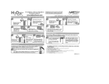
4. Use the blue funnel provided to pour the media into the tank. The order the media is
poured in is important. Begin by pouring the media labeled as Bag 1 (Quartz Gravel)
into the bottom of the tank. Pour it evenly around the hole to ensure it is well distrib-
uted in the tank and pour slow enough to keep from plugging the hole. Then proceed
to pour the media labeled as Bag 2 (Catalytic Carbon). A helper may be needed to
hold the funnel during the filling process. NOTE: It is recommended that a dust mask
and safety goggles be worn to prevent possible injury.
5. When the media is installed, move the tank side to side to settle the media. Remove
the funnel and cap from the distributor tube.
6. Lubricate the distributor O-ring and the outer tank O-ring
Need help? 1.800.608.8792 11 www.uswatersystems.com

7. Install the upper basket on the bottom of the valve by lining up the tabs then turning
the basket clockwise to lock it in place. Place the upper basket over the distributor
tube and push the valve onto the tank. Thread the valve on the tank by turning it
clockwise. Be sure not to cross thread the valve on the tank.
Need help? 1.800.608.8792 12 www.uswatersystems.com

8. Tighten the valve hand tight then snug it further by tapping it with the palm of the
hand. DO NOT use tools to tighten the valve or damage could occur.
Need help? 1.800.608.8792 13 www.uswatersystems.com

Water Meter Installation Instructions
1. After the sediment filter, install the water meter. There is a flow direction arrow on the
meter. Be sure the inlet plumbing is attached to the meter correctly. There should be
18" of horizontal pipe before and after the water meter to ensure it is reading proper-
ly.
2. Slide the nut over the connection nipple, apply Teflon tape and install it in the inlet
plumbing. Do not over tighten the plastic nipple or damage could occur.
Need help? 1.800.608.8792 14 www.uswatersystems.com

3. Install the rubber washer gasket in the connecting nut and install the water meter
with the flow arrow pointing away from the inlet fitting. Tighten the nut hand tight. An
adjustable wrench can be used to tighten the nut an additional 1/4 to 1/2 turn. The
rubber washer gasket will seal the connection so the nut should not be over tight-
ened.
Need help? 1.800.608.8792 15 www.uswatersystems.com

4. Slide the nut over the outlet nipple and install the outlet nipple in the outlet plumbing.
Use Teflon tape to seal the connection and tighten with an adjustable wrench. Do not
over tighten the nipple in the outlet plumbing connection or damage could occur.
5. Install the rubber washer gasket in the nut and tighten the outlet plumbing to the wa-
ter meter outlet connection. Tighten it hand tight then turn it an additional 1/4 to 1/2
turn with an adjustable wrench. Do not over tighten or damage could occur.
Need help? 1.800.608.8792 16 www.uswatersystems.com

Installation Instructions
1. If your hot water tank is electric, turn off the power to it to avoid damage to the ele-
ment in the tank.
2. If you have a private well, turn the power off to the pump and then shut off the main
water shut off valve. If you have municipal water, simply shut off the main valve. Go
to a faucet or spigot (preferably on the lowest floor of the house) and turn on the cold
water until all pressure is relieved and the flow of water stops.
3. Locate the backwashing tank close to a drain where the system will be installed. The
surface should be clean and level.
NOTE: Any solder joints being soldered near the valve must be done before con-
necting any piping to the valve. Always leave at least 6" (152 mm) between the con-
trol valve and joints being soldered when soldering pipes that are connected to the
valve. Failure to do this could cause damage to the valve.
The system is equipped with male pipe threaded ports on the control valve bypass.
The bypass is marked with arrows to show proper flow direction. The arrow pointing
toward the valve indicates the inlet. The arrow pointing away from the valve is the
outlet.
4. Insert the provided plumbing fittings into the bypass. 3/4" and 1" male pipe thread fit-
tings are supplied so ensure you pick the correct one for your plumbing. Tighten the
retaining nuts hand tight, ensuring that the fittings are not cross threaded.
5. Be sure to use Teflon tape or other pipe sealant on the plumbing fitting threads and
install them on the bypass accordingly. Use an adjustable wrench to ensure they are
tight.
NOTE: All piping should be secured to prevent stress on the bypass valve and
connectors.
Need help? 1.800.608.8792 17 www.uswatersystems.com

6. Install the reducing bushing in the tee fitting.
7. Install the tee fitting on the inlet port of the bypass and install the injection check
valve from the peroxide system in the open 1/2" hole in the reducing bushing.
8. Connect the outlet plumbing from the water meter to the open port on the inlet tee.
9. Now install the outlet plumbing for the bypass outlet port to the next piece of treat-
ment equipment or out to the home.
Need help? 1.800.608.8792 18 www.uswatersystems.com


/