Digital Watchdog DW-VMAXD1 User manual

Category
Digital Video Recorders (DVR)
Type
User manual
2
Warning
Unauthorized reproduction of all or part of this manual is strictly prohibited.
The FIGURES in this manual are only for illustration purposes. They may differ from the actual product.
The specifications and design of the product are subject to change without prior notice for purposes of quality
improvement.
Cautions
To get the best use out of the product, be sure to read the cautions before using the product.
For safety, please take note of the following:
Instructions Before Using the Product
To prevent electric shock when installing, moving, or opening the DVR and peripheral devices, connect and disconnect the cables as
instructed. All cables must be connected to grounded power outlets.
If the product is installed near a power outlet, make sure it can easily be unplugged.
Do not use the DVR in water or in wet places.
Keep the plastic packing materials used for the DVR or other peripheral devices out of reach of children (may cause suffocation).
Installation Environment of the DVR
Maintain the following conditions: operating temperature of 5˚C ~ 40˚C, operating humidity of 10% ~ 80%.
Install the DVR in a safe place that is free from external vibration.
Install the DVR in a well-ventilated place.
To protect the hard disk from data loss and breakdown, install the DVR away from magnetic materials.
When using a rack other than the standard one, use a separate table with sufficient spacing, i.e., 60cm from the floor, 50cm from the
ceiling, and 20cm from the side and back walls and other objects.
Safety Notes on the DVR
When installing additional boards and HDD, separate the power cable and completely turn off the power supplied to the DVR.
Keep the product away from heat-generating devices, such as heaters.
Do not use a damaged power cord.
To prevent problems due to magnetic interference and electric surge, use only grounded cables and power outlets.
If the power cord is connected, do not touch the power unit. If the power cord is connected, electric current is still flowing internally even
after the switch is turned OFF.
Do not place a heavy object on top of the product.
Do not drop a conductive object in the ventilation holes.
Allot sufficient space for system cabling.
Use only the parts indicated in the manual. Do not disassemble, repair, or modify the product without permission.
Incorrect system setup may cause malfunction.
Shut down the system normally as instructed in the manual.
Safety Notes on the Lithium Battery
Replace lithium batteries as instructed to avoid danger.
Dispose used lithium batteries properly.
Warning and Caution are indicated as follows.
Possible Injury or Product Damage
Risk of Minor Injury or Product Damage
Cautions for the Usage of the Product
Information for the Usage of the Product
PRECAUTIONS
3
1 INTRODUCTION .......................................................................5
Specifications .................................................................................................................................................. 5
Components .................................................................................................................................................... 5
Major Features ................................................................................................................................................. 6
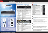
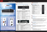
Front Panel View ............................................................................................................................................. 7
Rear Panel View ............................................................................................................................................... 7
2 INSTALLATION & CONNECTION .............................................8
Connection Order ............................................................................................................................................ 8
Terminal Block ................................................................................................................................................. 9
PTZ Camera & Keyboard Controller .............................................................................................................. 9
Sensor Connection ......................................................................................................................................... 9
Relay Connection ............................................................................................................................................ 9
POS Connection .............................................................................................................................................. 9
3 SYSTEM CONTROL ............................................................... 10
Remote Controller ......................................................................................................................................... 10
Mouse ............................................................................................................................................................. 10
Power ON ....................................................................................................................................................... 10
4 SETUP ................................................................................... 11
Time ................................................................................................................................................................ 12
Camera ........................................................................................................................................................... 14
Recording ....................................................................................................................................................... 20
Schedule ........................................................................................................................................................ 25
Disk Configuration ........................................................................................................................................ 26
Network Configuration .................................................................................................................................. 28
System ............................................................................................................................................................ 32
5 LIVE ....................................................................................... 35
Real-Time Live View ...................................................................................................................................... 35
Status Icons ................................................................................................................................................... 36
Control Bar ..................................................................................................................................................... 36
System Login ................................................................................................................................................. 37
System Logout .............................................................................................................................................. 37
Screen Division and Auto Sequence ........................................................................................................... 38
Zoom ............................................................................................................................................................... 39
Instant Recording .......................................................................................................................................... 39
6 SEARCH ................................................................................. 40
Express Search ............................................................................................................................................. 40
Jump to Last Saved Data .............................................................................................................................. 41
Jump to First Saved Data ............................................................................................................................. 41
Go to Last Played Time ................................................................................................................................. 41
7 PLAYBACK ............................................................................ 42
Playback Control Bar .................................................................................................................................... 42
Smart Search ................................................................................................................................................. 43
Express Search ............................................................................................................................................. 44
Multi Time ....................................................................................................................................................... 44
Multi Day ........................................................................................................................................................ 44
Multi Channel ................................................................................................................................................. 44
Panorama Playback ...................................................................................................................................... 44
Event ............................................................................................................................................................... 44
Audio .............................................................................................................................................................. 44
Backup ........................................................................................................................................................... 45
Zoom ............................................................................................................................................................... 45
De-Interlace .................................................................................................................................................... 45
TABLE OF CONTENTS
4
8 BACKUP ................................................................................ 46
Backup ........................................................................................................................................................... 47
Capture ........................................................................................................................................................... 48
Print ................................................................................................................................................................ 48
Log Backup .................................................................................................................................................... 48
Setup Backup ................................................................................................................................................ 49
NAS Backup ................................................................................................................................................... 49
9 PTZ ........................................................................................ 50
Setting a PTZ Camera ................................................................................................................................... 50
Controlling a PTZ Camera ............................................................................................................................ 51
10 SYSTEM INFORMATION ..................................................... 52
Version ........................................................................................................................................................... 52
System Log .................................................................................................................................................... 53
Miscellaneous Control .................................................................................................................................. 54
Monitor Configuration ................................................................................................................................... 55
Channel Grouping ......................................................................................................................................... 55
11 REMOTE ACCESS ................................................................ 56
Features ......................................................................................................................................................... 56
Connection ..................................................................................................................................................... 56
Live Mode ....................................................................................................................................................... 57
Playback Mode .............................................................................................................................................. 58
Management .................................................................................................................................................. 58
12 DNA ..................................................................................... 60
Setup .............................................................................................................................................................. 60
User Interface ................................................................................................................................................ 62
Configuration ................................................................................................................................................. 63
Playback ......................................................................................................................................................... 65
Control ............................................................................................................................................................ 67
Event ............................................................................................................................................................... 68
13 RAID .................................................................................... 69
Configuring RAID .......................................................................................................................................... 69
Destroying RAID ............................................................................................................................................ 70
APPENDIX ................................................................................ 71
Recommended HDD Specification .............................................................................................................. 71
Recommended PTZ Camera Protocol ......................................................................................................... 71
Recommended USB 2.0 Device ................................................................................................................... 71
5
Specifications
VMAXD1 16
VMAXD1 8
Full D1 Digital Video Recorder
Format
16Ch D1 480/400
8Ch D1 240/200
OS
Linux Embedded - Built in Flash Memory
Video Input
16 BNC
8 BNC
Video Output
Monitor
16 BNC, 1 VGA, 1 HDMI
8 BNC, 1 VGA, 1 HDMI
Spot
4 BNC - Single or Quad
1 BNC - Single or Quad
Audio Input
Line Input : 16 RCA
Line Input : 8 RCA
Audio Output
Line Output : 1 RCA
Compression Format
Video : Standard H.264 / Audio : G.723
Recording Speed
1/8, 1/4, 1 ~ 30(25)fps, Total max. D1 480/240(400/200)fps
Recording Resolution
CIF, 2CIF, 4CIF
Recording Mode
Continuous, Event (Sensor, Motion, Audio, Pattern, Text), Schedule
Alarm Interface
16 Sensor Input, NC/NO - Terminal Block
4 Relay Output, NC/NO - Terminal Block
8 Sensor Input, NC/NO - Terminal Block
2 Relay Output, NC/NO - Terminal Block
Video Output Resolution
HDMI : Full HD(1920x1080), WSXGA+(1680x1050), SXGA(1280x1024)
VGA : WSXGA+(1680x1050), SXGA(1280x1024)
BNC: SDTV(720x480(576))
POS / ATM Interface
8 RS232C Simplex - Terminal Block
4 RS232C Simplex - Terminal Block
Backup & Copy Access
eSATA, DVD-RW, USB2.0, Network
Network Access
Ethernet 10/100/1000 - RJ45
PTZ / Controller Access
RS485 Half Duplex - Terminal Block
Internal HDD / Internal ODD
SATA HDD Max. 4ea / SATA Type DVD 1ea(Without ODD, HDD 6ea)
System Operation & Adjustment
Front Panel Button, Mouse, IR Remote Control, Keyboard Controller, Network
System Upgrade
USB2.0 Memory Stick, Network
Network
System Automation (Controlled by CMS)
NTP Supported
CMS / Monitoring by Web Browser / PDA
Others
17 Languages Supported, Automatic E-mail
DC12V, 5A / Operating Temperature [5 ~ 40]
Weight without HDD [8kg] / Dimension [435 x 4445 x 88 mm]
Components
After unpacking the product, check whether the following accessories have been included. .
Remote Controller
Software CD
AAA 1.5V Batteries (2 Each)
Quick Start Guide
Handle
1 INTRODUCTION
6
Major Features
Advanced H.264 Linux Embedded DVR
HEXAPLEX Live, Playback, Recording, Backup, Network, Configuration
Full HD Output for Playback and Live Display
240fps at D1 for 8 Channel
480fps at D1 for 16 Channel
HDMI, Composite, & VGA Support
Jog Shuffle
Looping Output
Zoom-in Live and Playback
Multi-Record Scheduling
Pre- & Post-Event Recording
Programmable Privacy Zones
8 Sensor Input, 2 Sensor Output for 8 Channel
16 Sensor Input, 4 Sensor Output for 16 Channel
Time Server Function
NAS (Network Attached Storage) Backup Over Ethernet
Multi-User Access
Covert Channel
Network Bandwidth Control
Watermark Verification (Digital Signature Verification)
Go To, Multi-Date & Time, Calendar, Smart, Panorama, and Log Viewer Search
Smart Web Viewer for Live, Playback, Backup, Configuration
Remote Setup, Backup, and Relay Control
Mobile Application for Blackberry, iPhone, Android
Windows Mobile PDA Viewer
RAID 1,5: Rack Mount Available
DVD-RW Built-in
USB 2.0 Built-in
POS Support up to 8 Channel
RS-485 and 4/8 RS-232C Built-in
USB Mouse, IR Remote Control
Up to 6 Internal HDD Supported
7
Front Panel View
No
Name
Description
1
Power Button
Turn ON or OFF. Authorization is required.
2
Lock Button
Lock your system. Authorization is required.
3
Number Buttons
Select channel.
4
Status Indication
Indicates each functional status.
5
Optical Device Bay
Door for CD-ROM
6
Functional Buttons
Shortcut keys for the indicated function.
7
Directional Button and Select
Key
Use instead of mouse control.
Rear Panel View
No
Name
1
Power Supply
2
Camera Input, Loop Output, Audio Input, Spot Output
3
USB Connection (USB2.0, e-SATA)
4
Configuration Dip Switch (NTSC/PAL, Monitor Out)
5
RS232C for Console Output
6
Ethernet Port
7
VGA Output
8
HDMI Output for Full HD Display
9
Audio Out, TV Out, Terminal Block (Sensor & Relay Output)
8
Connection Order
By referring to the diagram above [Figure 2-1], make a connection accordingly.
Connect CCTV Camera Signal to BNC Input on rear panel.
Set video configuration with combination of dip switch.
Connect display monitor to TV OUT on rear panel.
No GUI is displayed through TV Out port.
Connect VGA monitor to VGA OUT on rear panel and HDMI monitor to HDMI on rear panel.
On VGA and HDMI Output, only the channel title is shown.
For higher resolution (greater than HD), only VGA Output is available.
Connect Spot Monitor to SPOT # on rear panel.
The following devices can also be connected:
Devices
DVR Terminal
Internal Hard Drives
6 SATA
Spot Monitor
4 BNC for 16 Channel
1BNC for 8 Channel
Audio
Each Channel
Sensor
Each Channel
Relay
4 for 16 Channel
2 for 8 Channel
POS
8 Connections for 16 Channel
4 Connections for 8 Channel
2 INSTALLATION & CONNECTION
9
Terminal Block
The terminal blocks located in the rear of the VMAXD1 are for the connection of the PTZ, Sensor, Relay, and POS. The number of
terminal blocks may vary depending on the model.
PTZ Camera & Keyboard Controller
Connect the PTZ control cable to the Terminal Block, TRXD+ and TRXD-, in the rear panel of the DVR.
You may refer to APPENDIX in this manual for supported PTZ cameras. A keyboard controller has the same connection as a PTZ
camera.
Sensor Connection
Depending on the model, connect the sensor to the terminal blocks S1 ~ S16.
Each input terminal is connected relatively with the channel number.
Sensor and Relay Type
NC (Normal Close): Normally Closed; opens when a signal is
received.
NO (Normal Open): Normally Open; closes when a signal is received.
Relay Connection
Relay the output signal to external devices, such as Alarm and Siren.
Connect the relay to R1, R2, R3, or R4 terminal block, depending on the model
POS Connection
Connect the POS Device.
Connect the POS to Terminal Block RXD1 ~ RXD8, depending on the model.
Depending on its type, the external alarm device may require a power
supply. Please be cautious.
10
The VMAXD1 series can be controlled easily by using the front panel buttons, front panel jog/shuttle, remote controller, and/or the mouse.
Remote Controller
No
Name
1
Power Button
2
Number Buttons in Input Number
3
DVR ID Button
4
System Operation and Setup
Menu: Enter Menu
Esc: Exit to Previous Mode
Search: Search Recorded Image
Select: Select Category or Execute Sequence
Copy: Copy Recorded Videos
Direction: Move within the Menu and Submenu
5
Up & Down: Move Up and Down on Log Page
PTZ: Shift to PTZ Camera Control Mode
6
Record Button
Sensor and Relay Type
NC (Normal Close): Normally Closed; opens when a signal is
received.
NO (Normal Open): Normally Open; closes when a signal is received.
Mouse
The mouse pointer, as shown below, appears if a mouse is connected to the USB terminal located at the front panel.
MOUSE CONTROL FUNCTIONS
Click Right Button
Monitoring Mode
Move from Monitoring Mode to Monitoring Setup
Open or Hide Play Menu
Show Submenu of the certain Setup window
Click Left Button
Select Setup
Double-Click Right Button
Select Setup
Double-Click Left Button
Move a certain window
Power ON
Check the VMAXD1 Series (100-240V, 50/60Hz) and connect the power.
Booting will be initiated by pressing the power button in the front panel.
After booting is finished, the Monitoring Screen, Channel Indication, and Clock are all displayed.
3 SYSTEM CONTROL
11
For Setup menu, click the right button of the mouse or press [Setup] button on the front panel.
ID and Password are required for initial installation. Default ID and Password are shown below.
Local Admin: 0000000, User1 : 1111111, User2 : 2222222, User3 : 3333333, User4 : 4444444
To change the password, right click on mouse, and click [Setup] >
[System] > [Admin. Password].
4 SETUP
12
Time
Right-click the mouse button; then select [Setup] > [Time].
Time Sync
Synchronize the time with the NTP (Network Time Protocol) server. The time will be synchronized with the NTP once every hour.
If synchronization with the NTP server fails, synchronization with RTC will be established.
Set the Time Sync to NTP or OFF.
If NTP is selected, input the Server Type and Server URL.
For automatic NTP setup, set Server Type to NTP and Server URL as Auto.
NTP setup is only available when Time Sync has been set to NTP.
The user can enter the IP only when the server type is DVR.
Date & Time
If Time Sync is set to OFF, set the date and time manually.
Use the mouse or the arrow keys and the SELECT button to set the Year, Month, Day, Hour, Minute, and Second on Date &
Time.
To complete the setting, click the SELECT button or click the right button on mouse.
Select the format you wish to display the date at Date Display Type. Select from DD/MM/YY, MM/DD/YY, and YY/MM/DD
Only available when Time Sync is off.
13
Time Zone
Select your local Time Zone.
Turn ON or OFF the daylight savings time (DST).
If DST has been set to ON, select the Start Time and End Time for DST.
For a weekly setting in the [Start Time] and [End Time] fields, set
Day to 0.
After the DST has been selected, the existing data will display as
“OLD_” in the search and log list.
Auto Reboot
To help keep your system healthy, configure your VMAXD1 to reboot automatically.
Use your mouse to set the Auto Reboot to ON or OFF...
Select the exact time for Auto Reboot, and select the day of the week you wish to perform Auto Reboot.
14
Camera
Right-click mouse button; then select [Setup] > [Camera].
Camera
To setup a camera, select the Camera tab.
Connect: Connect or disconnect the camera channel. ON means cameras is connected. To disconnect, turn camera OFF.
When the camera channel is set to disconnected, the video contents
will not be displayed even if the camera is actually connected.
Name: Name each camera.
Move mouse cursor above the name field and double click the left mouse button.
Input camera name on input panel. Up to 20 letters are allowed.
Covert: Turn ON to hide the camera on the monitoring screen and display a black screen.
Although the display screen is black, data is still being recorded and
saved, depending on the recording schedule.
PZ Mask: Used to hide a certain area of the real-time monitoring screen.
To setup the PZ Mask Area, move cursor above the PZ Mask field for the channel you wish to set and click the left mouse button.
The channel will be displayed with grid lines. Select the blocks you wish to mask by clicking and dragging the mouse.
Right click mouse button when setup has been completed.
Adjust: Select to adjust the camera’s Brightness, Contrast, Color, Saturation,
Sharpness, and Camera Position. When clicked, the single channel mode appears
with the Adjust window.
Excessively moving the camera up, down, right, or left may cause black or
gray areas to appear on the display screen. The level at which such
condition does not occur is based on the proper control range for the
camera.
15
PTZ
To setup a PTZ camera, select the PTZ tab.
Select the Protocol for the PTZ camera you are using.
Setup Camera ID and Baud Rate. Check your camera manual for the information.
Set a Tour, so camera can automatically move between different presets. Configure up to two Tours, and each tour can have up
to 8 presets
If a tour has been set, set the Duration for the staying time when the tour is activated.
POS
To setup a Point-of-Sale (POS) device, connect the POS device to the Terminal Block connection for RS232C.
Go to [Setup] > [Camera] > [POS], and select the protocol, baud rate, and character code for your POS device.
The VMAXD1 only indicates ASCII Characters.
16
When the POS device has been configured, setup the VMAXD1 to record any transactions sent from the POS device. Go to [Setup] >
[Recording] > [Recording], and make sure Text is set to ON.
User can perform a search by looking up an item on the POS transaction.
To perform a search based on POS transactions, click the right mouse button during Playback Mode, and click [Text Search] >
17
[CH##].
A Keyboard will appear. Using the mouse, type in the item you wish to search; then click Search button.
The keyboard is case sensitive.
The first recorded image with the item will appear. Use the Playback Control Bar to playback the video.
To move to the next or previous POS search result, use directional keys on the front panel or use the mouse and the control bar.
During playback, user can choose to display or hide the POS transaction on the recording video.
To hide the POS transactions, click the right mouse button during Playback Mode, and move the mouse cursor above [Text View].
Click the [CH##] you wish to hide the POS transactions.
The check mark next to the [CH##] will disappear, and the text on the playback video will also disappear.
To display the POS transaction, just repeat the previous steps.
Motion
Select the Motion tab to configure the motion detection settings.
18
Select Motion Area of each channel.
When clicked, the single channel mode composed of square boxes appears on the screen. Use the mouse to select areas you wish
to disable motion detection. Areas where motion detection is disabled will be indicated in the color brown.
Select Motion Area of each channel.
When clicked, the single channel mode composed of square boxes appears on the screen. Use the mouse to select areas you wish
to disable motion detection. Areas where motion detection is disabled will be indicated in the color brown.
Once motion area has been set, set the Motion Sensitivity, Sensor Type, and/or Sound Sensitivity.
Relay
Select from NO (Normally Open) or NC (Normally Closed).
If the wrong type is selected, relay will not work.
NO, which is normally open, closes when a signal is received.
NC, which is normally closed, opens when a signal is received.
19
Relay Output Connection
Relay output signal to external device such as Alarm or Siren.
Connect relay to R1, R2, R3, and/or R4 of the terminal block, located on the rear side with R#_Com Port.
Number of relay varies depending on the model of the DVR.
20
Recording
The Recoding setup is to configure the environment of the system’s record configuration and major functions.
VMAXD1 allows you to create a more detailed recording schedule by setting four unique record configurations.
Right-click mouse button; then select [Setup] > [Recording].
Select the specific schedule (Schedule1, Schedule2, Schedule3, Schedule4) you wish to configure, and change the settings for the
selected recording schedule.
Event
Configure the camera to record for the different types of eventMotion, Sensor, Audio, Pattern, Text.
Set the event as ON to record when the type of event occurs. If you do not wish to record, set as OFF.
All Event recording follows the Event Speed which can be configured at [Setup] > [Recording] > [Event Speed]. See “5.3.2 Recording”.
If none of the event options are turned ON, the VMAXD1 will record
continuously.
Event Type
Description
Continuous
The VMAXD1 will record continuously at the Normal Speed.
Motion
When the VMAXD1 detects motion, it will begin recording at the Event Speed.
Sensor
When an input signal from an external sensor is generated, the VMAXD1 will begin recording the event.
Audio
When audio is detected, the VMAXD1 will begin recording the event.
Text
When the POS device sends a transaction to the DVR, VMAXD1 will begin recording the event.
  • Page 1 1
  • Page 2 2
  • Page 3 3
  • Page 4 4
  • Page 5 5
  • Page 6 6
  • Page 7 7
  • Page 8 8
  • Page 9 9
  • Page 10 10
  • Page 11 11
  • Page 12 12
  • Page 13 13
  • Page 14 14
  • Page 15 15
  • Page 16 16
  • Page 17 17
  • Page 18 18
  • Page 19 19
  • Page 20 20
  • Page 21 21
  • Page 22 22
  • Page 23 23
  • Page 24 24
  • Page 25 25
  • Page 26 26
  • Page 27 27
  • Page 28 28
  • Page 29 29
  • Page 30 30
  • Page 31 31
  • Page 32 32
  • Page 33 33
  • Page 34 34
  • Page 35 35
  • Page 36 36
  • Page 37 37
  • Page 38 38
  • Page 39 39
  • Page 40 40
  • Page 41 41
  • Page 42 42
  • Page 43 43
  • Page 44 44
  • Page 45 45
  • Page 46 46
  • Page 47 47
  • Page 48 48
  • Page 49 49
  • Page 50 50
  • Page 51 51
  • Page 52 52
  • Page 53 53
  • Page 54 54
  • Page 55 55
  • Page 56 56
  • Page 57 57
  • Page 58 58
  • Page 59 59
  • Page 60 60
  • Page 61 61
  • Page 62 62
  • Page 63 63
  • Page 64 64
  • Page 65 65
  • Page 66 66
  • Page 67 67
  • Page 68 68
  • Page 69 69
  • Page 70 70
  • Page 71 71
  • Page 72 72

Digital Watchdog DW-VMAXD1 User manual

Category
Digital Video Recorders (DVR)
Type
User manual

Ask a question and I''ll find the answer in the document

Finding information in a document is now easier with AI