Page is loading ...

REV: 08/21

User’s Manual | 2
Safety Information
The safety information is provided for the wellness of the equipment and for the safety of the
operator.
Please review and observe all instructions and warnings in this manual.
Preparations before installation
To protect your DVR from damage and to optimize performance, be sure to keep the DVR away from dust, humidity, and
area with high voltage equipment such as refrigerator.
Do not install or place equipment in areas where the air vents can be obstructed, such as in tight enclosures or small utility
closet. Keeping the unit in a temperature-controlled room with ample regulated power is highly recommended. Do not
overload the wall outlet, as this can result in the risk of fire or electric shock.
Uninterruptible power devices such as UPS power surge protectors are recommended, and the DVR units must at least be
connected with UL, CUL, or CSA approved power surge protector. Avoid direct sun light and avoid heat.
FCC Information
This equipment has been tested and found to comply with the limits of Class A digital device,
pursuant to part 15 of the FCC Rules. These limits are designed to provide reasonable protection
against harmful interference when the equipment is operated in a commercial environment. This
equipment generates, uses, and radiates radio frequency energy, and if not installed and used in
accordance with the instruction manual, may cause harmful interference to radio communications.
Operation of this equipment in a residential area is likely to cause harmful interference in which case the user will be required
to correct the interference at his own expense. Changes or modifications not expressly approved by the party responsible
for compliance could void the user's authority to operate the equipment under FCC rules.
UL Information
- for pluggable equipment, the socket-outlet shall be installed near the equipment and shall be easily accessible
- if the battery is placed elsewhere in the equipment, there shall be a marking close to the battery or statement in the servicing
instructions.
C
AUTION
RISK OF EXPLOSION IF AN INCORRECT TYPE REPLACES BATTERY.
DISPOSE OF USED BATTERIES ACCORDING TO THE INSTRUCTION.
THIS EQUIPMENT IS FOR INDOOR USE, AND ALL THE COMMUNICATION WIRING IS LIMITED TO
INSIDE OF THE BUILDING, OR ANY SIMILAR WORD.
Note : Keep this manual handy every time you operate this equipment. Also, check with your dealer
for further assistance and for the latest revision of this manual. Your dealer might provide you with a
digital version of this manual. We also ask to keep the original box and packing materials in case of
return and for long-term storage of the DVR unit.

3 | VMAX960H CORE™ Digital Video Recorder
Contents
CHAPTER 1 : DVR USER MANUAL
1 GETTING STARTED 6
1.1 Checking Supplied Items 6
1.2 Connecting Peripheral Device 7
1.3 System Startup and Shutdown 8
2 EXPLANATION FOR EACH FUNCTION 10
2.1 Front Panel 10
2.2 Rear Panel 11
2.3 IR Remote Controller 13
3 OPERATION 14
3.1 User Log-in 14
3.2 Quick Startup Wizard 15
3.3 Live Display Mode 16
3.4 PTZ Operation 20
3.5 Call Monitor Operation Error! Bookmark not defined.
3.6 Playback of Recorded Video 22
3.7 Quick Backup during Playback 23
3.8 Search Recording Image 24
3.9 DST Setting 27
3.10 Screen Saver 28
4 SETTING 29
4.1 System 30
4.2 Device 36
4.3 Record 41
4.4 Network 44
4.5 Backup Error! Bookmark not defined.
4.6 Quick Setup 50
5 WEB CLIENT 51
5.1 Web Login 51
5.2 Web monitoring 52
5.3 Web Playback 55
5.4 Web Configuration 56
6 PIVOT™ USER GUIDE 58
6.1 PC Requirements 58

User’s Manual | 4
6.2 Software Installation 58
6.3 Software removal 59
6.4 Basic Operations 60
6.5 Pivot Functions 70
6.6 Pivot Setup 76
7 MAC ACS USER GUIDE 82
7.1 System Requirement 82
7.2 Install 82
7.3 Basic Operation 84
8 MOBILE PHONE SOFTWARE USER GUIDE 90
8.1 iPhone application software 90
8.2 Android application software 100
9 APPENDIX : NETWORK SETUP FOR EXTERNAL USAGE 110
10 APPENDIX : SPECIFICATION 112

5 | VMAX960H CORE™ Digital Video Recorder
Chapter 1
DVR USER MANUAL

User’s Manual | 6
1 GETTING STARTED
1.1 Checking Supplied Items
Make sure that you have the following items supplied with your DVR. If any of these items are missing or damaged, notify your
vendor immediately. Keep the packing utilities for moving or storage purposes afterwards.
Items
Photo
Quantity
Quick Start Guide
1 Set
CD (Manual & Software)
Rubber Mount
1 Set
1 Set (4 Pieces)
12V DC Adaptor
Power Cable
1 Set
USB Mouse
1 Set
Screws
4 Pieces (Top cover )

7 | VMAX960H CORE™ Digital Video Recorder
1.2 Connecting Peripheral Device
This section describes how to connect peripheral devices efficiently to the DVR.
Install the DVR on flat surface. If required, attach a rubber mount for installation. If a 19-inch rack is used with 1.5U Height
case, it is recommend to install the system on a shelf and use 2.5~3U (1U=1.75 inch or 4.45 cm) space for proper ventilation.
4 Channel DVR Compact Case Dimensions: 11.0” W x 1.9” H x 9.6” D
8 Channel DVR Compact Case Dimensions: 11.0” W x 1.9” H x 9.6” D
16 Channel DVR Compact Case Dimensions: 14.1” W x 2.6” H x 14” D
NOTE
Install the system in a location with good ventilation to prevent overheating.
W
ARNING
!
※When connecting power cord to the system, it is strongly recommended first to plug the power cord
to the system and then plug the other side of power cord into the wall socket.

User’s Manual | 8
1.3 System Startup and Shutdown
1.3.1 System Startup
After connecting all necessary peripheral devices such as cameras, monitors and a mouse to the DVR, power up the DVR by
connecting DC12V 3A adaptor to the power jack on the rear panel. The boot log screen will appear. Please wait until the boot
process is complete.
To login, right-click anywhere on the screen. This will bring up the login screen, where you can enter the username and
password. There is only one Administrator Account configurable in the DVR system. It is assigned with an unchangeable
User ID marked as ‘admin’. The default password is empty (No Password). Administrator account has full access to the DVR
and its configurable parameters. The Administrator Account also has the ability to create new users and to assign rights to the
new user accounts. Those new users created by the Administrator can also login with a specific password set by the
Administrator.
N
OTE
Do not forget the administrator’s password that was set for the first time. In case the password is lost,
contact your vendor.
N
OTE
The mouse is included. In case you need to replace it, it is highly recommended to choose well-known
major brands such as DELL, MICROSOFT, LOGITECH, or SAMSUNG.

9 | VMAX960H CORE™ Digital Video Recorder
1.3.2 System Shutdown and change password
To power off the DVR, follow one of the options below:
1. Right-click on the screen and select ‘Shutdown’ from the drop-down menu. Enter the username and password to power
off the DVR.
2. Right-click on the screen and select ‘Setup Menu’. Go to the System Settings sub-menu and select the ‘Default’ tab.
Press the ‘Shut Down’ button at the bottom right of the window. Enter your username and password and select OK to
power off the DVR.
N
OTE
It is not recommended to disconnect the power cable abruptly from the back of the DVR because it may
affect the DVR and Hard Drive.
The default password for ‘admin’ account is none. Therefore, just click ‘Enter’ button on the dial pad. If you changed the
password for ‘admin’ account, please type in the changed password to login.
N
OTE
User can type in the password using the virtual keyboard or the numeric buttons on the IR remote
controller.

User’s Manual | 10
2 EXPLANATION FOR EACH FUNCTION
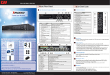
2.1 Front Panel
4Ch/8ch DVR Front Panel (1U Case / 1 HDD)
16ch DVR Front Panel (1.5U Case / 2 HDD)
No.
Items
Functions
1 LED Indicator
System status LED indicators
Green = The system is powered and ON.
Red = The system is currently recording
Yellow = The system is being accessed remotely via the network
2 USB Port USB Port (Ver. 2.0) for mouse operation, backup device or firmware update

11 | VMAX960H CORE™ Digital Video Recorder
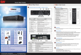
2.2 Rear Panel
4 Channel DVR Compact Case
8 Channel DVR Compact Case
16 Channel DVR Compact Case

User’s Manual | 12
No.
Name
Description
1
Video-In
Camera Inputs
2
Audio-In
Audio Input Device (with Amplifier)
3
Audio-Out
Audio Output Device (with Amplifier)
4
USB Port
USB 2.0 Port for Mouse Operation, Backup Device and Firmware Update
5
HD OUTPUT
HD Output for Local Monitoring
6
LAN Port
1 x 10/100/1000M RJ59 Port for Network Connection
7 Power Input
4ch : 12V/2A
8ch : 12/3A
16ch : 12V/5A
8
Alarm Output
Alarm Output
9
Sensor Input
Sensor Input
10
RS-485 Port
PTZ Dome Camera or External Keyboard Controller Connection
11
VGA
VGA Output
12
LOOP OUT
Looping Output ports (DW-VLOOP Sold Separately) (16ch Models Only)
Note
Carefully check whether the specifications of the peripheral devices match the DVR’s specifications.

13 | VMAX960H CORE™ Digital Video Recorder
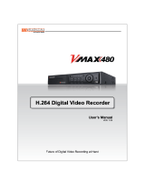
2.3 IR Remote Controller
The VMAX960H CORE DVR comes with a complimentary IR remote controller. In order to use the remote controller, the ID
must match on both the DVR and the controller.
(Default ID # for DVR and IR Remote Controller is “1”.)
If you have more than two DVRs, you can control them with the same remote controller by setting up their ‘Remote ID’ from
‘1’ up to ‘8’.
The function buttons of the IR Remote Controller are as below.
No.
Functions
1
Start/ stop instant (emergency) recording
2
Numeric buttons for channel view selection and text input
3
Auto-sequence on live display
4
Freeze current view
5
Go to call monitor view
6
View next /previous channel in single channel view
7
Start instant playback
8
Open search menu
9
Ok (select) button
10
Mute audio
11
Playback on Search Mode
12
(Fast Backward/Playback/Stop/Fast Forward)
13
Exit
14
Display mode
15
PIP Mode
16
Bookmark
17
Zoom in & out
18
Backup button
19
Enable PTZ control
20
Directional buttons (up/down/right/left)
21
Open setup menu

User’s Manual | 14
3 OPERATION
3.1 User Log-in
The DVR has various setting categories. The administrator can set the system password and <User> to prevent
unauthorized changes to setting values and alteration of recorded file.
Enter the <Admin> or <User> password which had been set by using the virtual keyboard.
N
OTE
1) <LOGIN> window will be displayed until user logs in with the right ID and password.
2) If the DVR is set to Auto Log-In, DVR does not require LOG-IN. (Please refer to 4.1.2 User.)

15 | VMAX960H CORE™ Digital Video Recorder
3.2 Quick Startup Wizard
Quick Startup Wizard is specially designed to make it much easier for the major DVR settings such as Time/Date setup,
Record setup, Network setup and Quick setup. When the DVR boots up, the Quick Startup Wizard operates automatically. It
can be disabled by setting in the main menu.
Adjust the date & time for the DVR.
Setting this before the DVR starts
recording will prevent and time
conflict, which may result in data loss.
See section 4.1.1 System Info for
more information.
See section 4.4 Network for more
information on setting up the DVR for
external connection.
Use the DVR recording calculator to
setup the best recording parameters
for your needs. See section 4.6 Quick
Setup for more information.

User’s Manual | 16
3.3 Live Display Mode
3.3.1 Full HD(1080p) Live Display
Full HD Live Display can be supported in live mode by using its HD output.
NOTE
In playback mode, the maximum resolution is 960x480 / 960x576(NTSC/PAL).
<Full HD Live Display>
3.3.2 Channel Selection
Channel selection can be done by following one of the steps below:
1. CH1~CH16 buttons in the IR Remote Control.
2. 1~16 virtual buttons at the bottom of the GUI display.
The display mode can be changed by selecting the appropriate display mode from the menu bar at the bottom of the display
area.
The live images can be displayed in real-time in 1, 4, 9, 16 screen splits (depending on the model and the supported
channels). Whenever the left/right arrow button on the front panel or IR remote controller is pressed, the screen will be
sequentially changed.
[1 Ch] [4 Ch]

17 | VMAX960H CORE™ Digital Video Recorder
[9 Ch] [16 Ch]
To select a channel to view in single channel mode, click on the channel using the USB mouse. To return to the previous
display mode, click anywhere on the screen again.
To view the pop-up menu, right-click anywhere on the display screen.
NOTE
To select a channel using the mouse, perform a slow and clear click of the left mouse button.
3.3.3 Icons
The live mode display’s icons or messages will be indicated on the screen to indicate the system mode or status.
Below are the icon categories that are indicated on the monitor:
Icon to be shown
at Left-upper corner on each channel screen
Icon to be shown
at Left-bottom corner on full screen.
Continuous Recording
Sequence display on
Motion Detection Recording
Digital zoom on
Sensor Activating Recording
Audio Channel
Continuous+ Motion Recording
Continuous + Sensor Activating
Recording
Emergency Recording
N
OTE
If you cannot find any colored-mark in the top right corner of the live screen mode, then the system is not
set to record any image. Check the recording schedule or camera in the main setup menu.
To show the menu bar, move the mouse’s cursor to the
bottom of the screen. The menu bar will be displayed.
To hide the menu bar, move the mouse’s cursor away from
the menu bar.
Right-click the USB mouse to access the pop up menu.

User’s Manual | 18
Menu Bar
Menu button. When pressed, System Setup, Search, Backup, Logout will appear.
Screen split options- Select from single channel, 4 channel, 9 channel, or 16-channel display.
Sequence- if pressed, the system will start displaying all the channels in sequence mode. To
stop, press the button again, or right click on the screen and select ‘SEQUENCE’
CH. Buttons- view a specific channel in full screen mode.
Instant (emergency) recording- The system will record video based on the panic record
settings (Default: 30fps @ 960x480).
PTZ mode- Control any supported PTZ cameras by moving the mouse pointer.
Go to Instant playback.
HDD usage indicator- Indicates the percentage of your HDD being used. If it shows 60%, then
60% of HDD space has been used.
3.3.4 Pop-up Menu
Right clicking anywhere on the screen will open up the pop up sub-menu as shown below.
D
ISPLAY- Select the display split from the available options:
- 1 Screen- Single channel. Automatically displays CH1. If 1 Screen is selected again, next chronological channel will be
displayed.
- 4 Screen- Quad mode. Automatically displays channels 1~4. If 4 Screen is selected again, the next chronological 4
channels (5~8) will be displayed.
- 9 Screen- Automatically displays channels 1~9. If 9 Screen is selected again, the next chronological channels
(10~16+1~2) will be displayed.
- 16 Screen- Displays all 16 channels (available only in 16 channel models)
PTZ CONTROL- Open the DVR’s PTZ control. See section 3.4 PTZ for more information.
SEQUENCE- when selected, icon will appear on the bottom right corner of the screen, and the display screen will
change sequentially (Please note, this option will be disabled if display area is in 16 channel mode).

19 | VMAX960H CORE™ Digital Video Recorder
ZOOM- Enables/ disables digital zoom function. When enabled, icon will appear and zoomed area will be
displayed on the bottom right corner. The Zoom will automatically focus on the center of the camera’s display. To adjust it, go
to the small zoom display at the bottom of the camera display and move the yellow frame to the area you would like to view.
To move the yellow frame, use your mouse to drag the lines to the desired location. To go back to live display mode, right-
click on the screen and select “ZOOM” again. This feature is available in single channel mode only.
INSTANT REC- Start/ Stop Panic Recording.
PLAYBACK- Select playback option:
- 10, 15, 30, 60 seconds- start playback from the selected number of seconds ago.
- 2, 3, 5, minutes- start playback from the selected number of minutes ago.
- Open Playback Mode- automatically go to instant playback.
SEARCH- Select video search options:
- Date/ Time- open calendar search.
- First/ Last Data- Go to the first or last recorded data.
- System/ Event Log- open log search window.
- Bookmarks- open bookmark search.
BACKUP- Open the backup screen to export data from the DVR to an external USB drive.
SETUP- open the DVR’s main menu.
SHUT DOWN- Power off the DVR.
LOGOUT- User logout.
When a camera is disconnected, a warning sound may be generated depending on the system settings.
As the Admin user, you can setup up multiple users with different levels of authorization. If a certain user is not allowed to
view a certain camera in live or playback, then no image will appear on the display screen. To create, delete, or modify users,
go to the main menu and select system settings. See section 4.1.2 User for more information.

User’s Manual | 20
3.4 PTZ Operation
Before starting PTZ control, please make sure the camera you wish to control is a supported PTZ camera and is installed and
configured properly. See section 4.2.6 PTZ for setup information. To enter PTZ mode, follow one of the options below:
1. Right-click on the screen and select PTZ Control.
2. Click on the joystick button in the menu bar located on the bottom of the main screen.
3. Press the PTZ button on the IR remote control.
In PTZ mode, user can control PTZ operation with the USB mouse.
While pressing the left button of the mouse, drag the mouse pointer up/down, left/right to move the camera’s pan/tilt position
accordingly. The further away from the center of the screen you move the mouse, faster will the camera move. You can also
zoom-in/out by rolling the wheel of the mouse up or down.
N
OTE
Full PTZ functions are available by using USB mouse, IR remote control, or keyboard controller and are
available only on supported PTZ cameras.
For focus control: In PTZ mode, right-click to get the pop-up menu as shown below. Default mode is to “ZOOM”. Select
“FOCUS” to switch the mouse’s wheel function from zoom-in/out to focus near/ far.
The user can also select the preset button to start/ stop a preset, or exit PTZ screen model..
NOTE
User will see numeric pad to select “Preset” number. The preset is defined by setting a PTZ protocol in
the setting menu. The maximum number of preset is 255, but the number of available presets may vary
by camera make and model
/