Fig D.
Fig C.
62XX-501-36
9A487001
Installation Instructions
INS-9A487001 (Rev. A)
1
2
3
4
With a phillips head screwdriver, loosen the
top bracket screws by approximately a 1/4”
(See Fig. A).
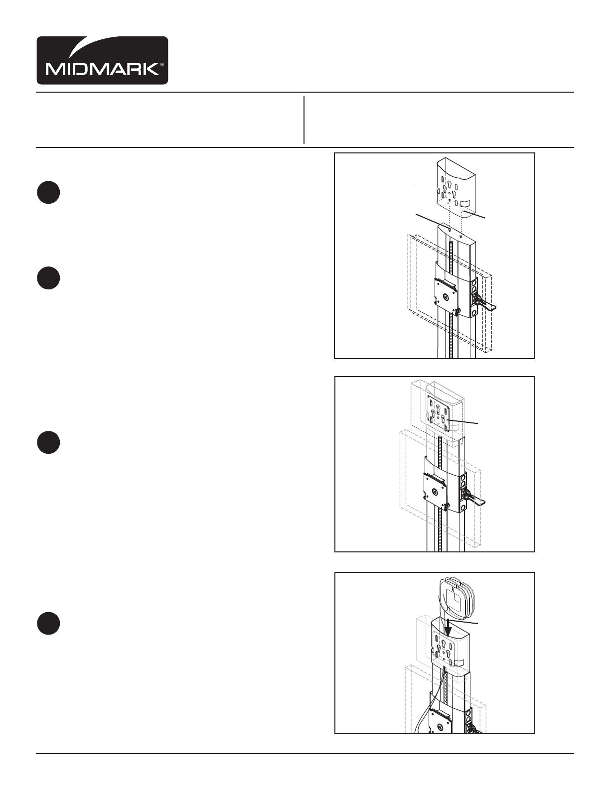
Install Top Mount CPU-9 into wall extrusion
and into keyhole slots and slide sideways
into place (See Fig. B).
Tighten two screws.
Attach thin-client to vesa pattern plate.
Install thin-client plate assembly within the
(3) keyhole slots. When installed properly the
safety release button will snap into place
(See Fig. C).
Cable Management:
Take extra length of cables and wrap them
around cable management power curl. Slide
power curl into Cable basket (See Fig. D)
Fig A.
Fig. B.
Midmark Corporation | 60 Vista Drive | PO Box 286 | Versailles, Ohio 45380-0286 | USA | midmark.com
Tools required:
#2 Phillips Drive Screw Driver
Flat Head Screw Driver
Parts Included:
(1) Top Mount CPU Holder
(1) Power Curl Cable Manager

