Installation Instructions
For Pre-Attached Rosettes & Short Plates
Passage and Privacy
Door Handing - Rosettes and Short Plates
With step-by-step Installation Pictograms & Drilling Template
Applies to:
• Classic and Rope Rosettes with levers
• Cottage and Studio Short Plates with levers
Tools Required: #2 Phillips Screwdriver (Not power tools)
Door handing is critical for Split-Finish, or Split-Design products. It’s also used to determine where
the Interior and Exterior halves of the lockset are located on the door. And, it’s used to position the
latch tongue in relation to the strike plate.
INSTALLATION RULES:
1) Lockset machine mounting screws are inserted from the inside.
2) Privacy pin holes are next to the door side containing the latch.
3) Latch tongues have a beveled side, and this side should contact
the curved end of the face plate, and curved end of the strike plate.
(See *Latch Tongue Note on page 3.)
Inside of Door
- The Inside of a door refers to the side of the door that faces the room. For example,
for a bedroom door on a hallway, the Inside of the door would face the bedroom.
Outside of Door - The Outside of a door refers to the side of the door that faces away from the room.
The Outside of a door is generally more visible to visitors, and therefore a rosette on this side of the
door has no visible screws. For example, on a bedroom door, the Outside would face the hallway.
outside
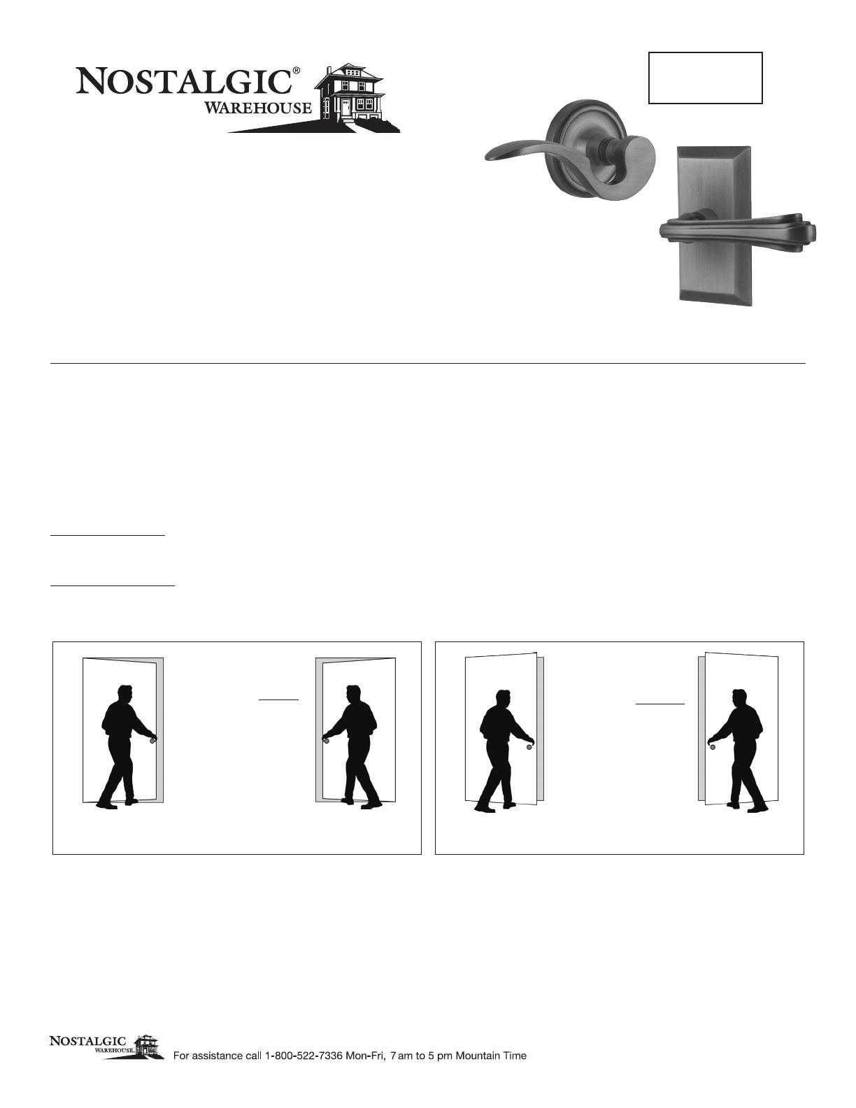
To identify door handing,
face door from the Outside.
outside
DOORS OPENING INWARD
Hinge is on the left.
Door is Left Hand.
Hinge is on the left.
Door is Left Hand.
Hinge is on the right.
Door is Right Hand.
Hinge is on the right.
Door is Right Hand.
To identify door handing,
face door from the Outside.
DOORS OPENING OUTWARD
outsideoutside
Page 1 - PK#300 08012019
LEVER


