
Installation Instructions
For Pre-Attached Rosettes & Short Plates
Passage and Privacy
Door Handing - Rosettes and Short Plates
With step-by-step Installation Pictograms & Drilling Template
Applies to:
• Classic and Rope Rosettes
• Cottage and Studio Short Plates
Tools Required: #2 Phillips Screwdriver (Not power tools)
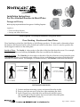
Door handing is critical for Split-Finish, or Split-Design products. It’s also used to determine where
the Interior and Exterior halves of the lockset are located on the door. And, it’s used to position the
latch tongue in relation to the strike plate.
INSTALLATION RULES:
1) Lockset machine mounting screws are inserted from the inside.
2) Privacy pin holes are next to the door side containing the latch.
3) Latch tongues have a beveled side, and this side should contact
the curved end of the face plate, and curved end of the strike plate.
(See *Latch Tongue Note on page 3.)
Inside of Door
- The Inside of a door refers to the side of the door that faces the room. For example,
for a bedroom door on a hallway, the Inside of the door would face the bedroom.
Outside of Door - The Outside of a door refers to the side of the door that faces away from the room.
The Outside of a door is generally more visible to visitors, and therefore a rosette on this side of the
door has no visible screws. For example, on a bedroom door, the Outside would face the hallway.
outside
To identify door handing,
face door from the Outside.
outside
DOORS OPENING INWARD
Hinge is on the left.
Door is Left Hand.
Hinge is on the left.
Door is Left Hand.
Hinge is on the right.
Door is Right Hand.
Hinge is on the right.
Door is Right Hand.
To identify door handing,
face door from the Outside.
DOORS OPENING OUTWARD
outsideoutside
Page 1 - PK177 04202017

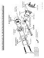
Exterior Half of
Lockset
Spindle
Spindle Button
Locking Mechanism
(Threaded Privacy-Pin Hole)
Privacy
Pin Hole
Privacy Pin
Anti-Rotation
Block
1-1/2” Machine Screws
(1-3/8” thick doors), or
1-3/4” Machine Screws
(1-3/4” thick doors)
Latch
Latch Tongue
Strike Plate
3/4” Flat Head
Wood Screws
Faceplate
Emergency
Release Hole
Interior Half of
Lockset
Exploded Drawing for Pre-Attached Rosette/Short Plates Passage/Privacy
Privacy Emergency
Release Key
Page 2 - PK177 04202017

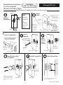
Passage/Privacy
Installation Instructions
For Pre-Attached
Rosettes and Short Plates
Tools Required: #2 Phillips Screwdriver (Not power tools)
Fits doors
1-3/8” to 1-3/4” thick
Attach the strike plate to the door jamb
using 3/4” long wood screws.
Door
Jamb
Install Strike Plate
Door - Inside
Screw in the
Privacy Pin
(Privacy Only)
Install Privacy Pin
Door - Inside
Install interior half of lockset
with 1-1/2” machine screws
(1-3/8” thick doors), or 1-3/4”
machine screws (1-3/4” thick
doors)
Install Interior Half
of Lockset
Door - Inside
Install
Exterior
Half of
Lockset
Emergency
Release Hole
(Privacy Only)
Push spindle button
down and hold during
insertion
1
2
Insert
Spindle
Insert
Spindle
Door - Inside
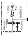
Latch
Tongue
*
Latch Tongue Note
Bevel Side
Face Plate Curve
Strike Plate Curve
Threaded
privacy hub
goes on the
inside of the
door.
Bevel side of latch tongue should
contact curved end of face plate,
and curved end of strike plate.
Install latch and rotate
the latch tongue
to change handing.
(See page 1 for handing)
Install anti-
rotation block.
Be certain
the arrow is
pointing to
the edge of
the door.
Install faceplate with
3/4” wood screws.
(Anti-Rotation
Block)
Arrow
1
2
3
Door - Inside See Latch Tongue
Note in next panel
*
*
Install
Latch
For 2-3/8”
Backset:
For 2-3/4”
Backset:
Backset
Information
NOTE:
DRILLING
TEMPLATES
ON
SEPARATE
INCLUDED
SHEET
Page 3 - PK177 04202017

MEASURE FROM THE FLOOR TO THE CENTER
OF EXISTING LOCKS, AND USE THIS DISTANCE
AS THE CENTER OF THE DUMMY MOUNT. IF THERE
ARE NO EXISTING LOCKS, POSITION THE DUMMY
MOUNT 36” TO 38” FROM THE FLOOR.
2 FOLD TEMPLATE ALONG DOTTED LINE,
AND POSITION FOLD ON THE EDGE OF THE DOOR.
TAPE TEMPLATE TO FACE OF DOOR.
3 BEFORE DRILLING VERIFY THE
BACKSET OF YOUR EXISTING DOORS
IN YOUR HOUSE. DRILL PILOT HOLES
USING A 7/64” DIAMETER BIT.
4 INSERT THREE WOOD SCREWS,
SLIDE ROSETTE OVER MOUNT,
AND SCREWON KNOB.
5 INSERT HEX SCREWS
AND TIGHTEN.
FLOOR
DUMMY MOUNT
(1)
TEMPLATE
EDGE OF DOOR
FACE OF DOOR
Page 4 - PK177 04202017
-
 1
1
-
 2
2
-
 3
3
-
 4
4


Ask a question and I''ll find the answer in the document
Finding information in a document is now easier with AI
Related papers
Other documents
-
Nostalgic Warehouse 701967 Operating instructions
-
Nostalgic Warehouse 722772 Operating instructions
-
Grandeur Hardware 850601 Installation guide
-
Grandeur 807484 Installation guide
-
Nostalgic Warehouse 714400 Operating instructions
-
Nostalgic Warehouse 771875 Installation guide
-
Nostalgic Warehouse 718432 Operating instructions
-
Nostalgic Warehouse 700228 Operating instructions
-
Nostalgic Warehouse 705711 Operating instructions
-
Nostalgic Warehouse 762645 Installation guide