
1
Model
Thank you for purchasing this FL-910 lens unit for HITACHI projectors.
Prior to use, read the user manuals of both this product and your projector thoroughly and follow their instructions.
After reading the User's Manual, keep it in a safe place for future use.
This product consists of the lens mount brackets and option lens (FL-900) for HITACHI projectors.
Notice
●Thecontentofthismanualissubjecttochangewithoutnotice;thisincludestheproductspecications.
●HITACHIwillnotbeliableforanyinjuriesordamageduetoimproperuseorapplicationoutsidetheintendedscope.
FL-910 Projector Lens Unit
FL-910 Projector Lens Unit User’s Manual
Symbols
This manual uses the following symbols to help you and any helpers use the product safely and according to
instructions, in order to prevent any injury or property damage. Please read thoroughly so you understand them and
use the product accordingly.
Warning
Ignoring this symbol and handling the product incorrectly may result in serious injury or
death.
Caution
Ignoring this symbol and handling the product incorrectly may result in injury and/or
property damage.
Table of Contents
Symbols .................................................. 1
Overview.................................................2
Important Considerations for Installation
...2
Periodic Inspection .................................3
Checking the Contents of Packaging .....4
Mounting the Brackets ............................7
When Using on a Tabletop ...................10
When Using the Ceiling Mount Bracket
(HAS-404U) ..........................................10
This symbol indicates prohibited actions.
The description after this symbol indicates actions that are not allowed to be performed.
This symbol indicates mandatory actions.
The description after this symbol indicates actions that must always be performed.

2
Special skills are necessary for installing this product. Be sure to ask the sales outlet or a service company (See the
User's Manual of your HITACHI projector) to perform the installation job.
Pay particular attention to the following points when mounting a projector on the ceiling.
1. Before performing the mounting design and construction work, verify that the weight of the projector and ceiling
mount with 6-axis adjustment (HAS-404U) can be fully supported.
2.
To protect itself, the projector has a temperature sensor that turns off the power if its internal temperature rises
abnormally.
Follow the instructions below to prevent the temperature from rising abnormally.
(1) Do not install in locations where the temperature is outside the operating temperature range indicated in the
projector's User's Manual.
(2)Periodicallycleantheairlterontheinsideoftheairintake.Seeyourprojector'sUser'sManualforinformation
on cleaning frequency and method.
(3) If installed in a location with lots of dust, the cleaning mentioned in (2) has to be done more frequently, so
mount in a location where it can easily be cleaned.
(4) To facilitate ventilation from the exhaust outlet, allow for at least 30cm of space around the projector.
(5) Do not install in locations that are subject to sudden changes in temperature, such as near an air conditioner, or
where the temperature exceeds the operating temperature indicated in the projector's User's Manual.
3.
If r
esidue from tobacco gets on the optics of the projector, it deteriorates its projection performance. Do not install
in a l
ocation subject to excessive tobacco smoke.
4.
T
he remote control may not function properly if the remote control signal receiver on the projector is subject to
stronglight,suchasdirectsunlight,oruorescentlightingatpointblankrange.Installsothereceiverisnotsubject
to direct light.
Important Considerations for Installation
Overview
This product includes the lens mount brackets and option lens (FL-900) for HITACHI projectors.

3
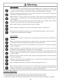
Warning
To the customer:
■Thecustomershouldneverattempttoperformtheinstallationwork.Pleasehavethesalesoutlet
or service company perform the installation. Please be warned that we shall bear no responsibility
whatsoever for any accidents or injuries that occur from improper installation or handling.
■Installataheightwherepeoplewillnothittheirheadontheprojector.Iftheprojectorisinstalledata
low position, be extremely careful when using.
■
After installation, do not hang down from the projector or ceiling mount with 6-axis adjustment
(HAS-
404U).
An injury or damage could occur due to the projector falling, the bracket becoming bent, or
other breakage.
■
Do not install in locations exposed to large amounts of humidity, dust, or cigarette smoke, locations
exposed to oil smoke or steam, or locations where salt damage can occur.
■
Do not install in locations exposed to large amounts of vibrations.
■
Once installation is completed, store this manual and the accessories in a safe location.
■
Be careful when handling the small parts. They could be ingested by children or pets. If a part is
ingested, seek medical attention immediately.
To the installer:
■InstallthisproductproperlyaccordingtothisUser'sManual.Installallthescrewsandhardwareas
indicated.
■
Before performing the mounting design and construction work, verify that the weight of the projector
and ceiling mount with 6-axis adjustment (HAS-404U) can be fully supported.
■
Never modify the ceiling mount with 6-axis adjustment.
(The strength can no longer be guaranteed
onceitismodied.)
■Afterperformingthemountingadjustment,checkthatthescrewsaresecuredinplaceatthe
speciedforce.Becarefulthatnoscrewsarelooseorover-tightened.
■Donotusescrewlockingadhesive,lubricants,oils,orothersolventsontheanchoringsectionofthe
projector ceiling mount because the case could break or the projector could fall, resulting in an injury
or other accident.
■Installandroutethepowerandothercablesthroughthedesignated locations,andbecarefulthat
they are not damaged.
■Carefullyreadtheprojector'sUser'sManualpriortoperforminganyinstallationwork,andinstall
correctly by following all safety precautions.
■Priortoinstallation,makesuretheprojectorisOFFandunplugthepowercord.
■Donotinstallinlocationswhereoilisused. Oilcanadhereduetooilsmokeorothersubstances,
resultinginabreakdown,re,orelectricalshock.Itcanalsocausedeteriorationoftheplastic,which
can result in an injury due to parts falling from the ceiling or elevated locations.
Periodic Inspection
As a general guideline, inspect the points below once per year in the same way as the set unit.
1. Check that the screws of the ceiling mount brackets and adjustment locations are not loose.
2. Inspect that the ceiling mount brackets, adjustment parts, set unit, and other parts are not broken or damaged.

4
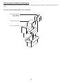
Make sure the following items are packed inside the box. If something should be missing, contact the sales outlet right
away.
Accessories Packaged with FL-910 Lens Unit
Checking the Contents of Packaging
Lens mount bracket
Lens Mount bracket
User's Manual
(this manual)
Option lens FL-900

5
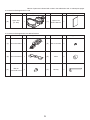
Code Part Name Qty. Appearance Code Part Name Qty. Appearance
(A) Mount bracket A 1
(D) M4×10 screws 2
(B) Mount bracket B 1 (E) Collar 2
(C)
M6×16
Hex-head screw
4 (F) Hex key 1
Code Part Name Qty. Appearance Code Part Name Qty. Appearance
(H)
Option lens
(FL-900)
1 (
I
)
Option Lens
User's Manual
1
Names of parts are indicated with codes in the table below and on subsequent pages.
●AccessoriesPackagedwithLensMountBracket
●AccessoriesPackagedwithFL-900

6
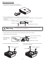
1. Remove the option lens FL-900 (H) from the box.
For details on operating the option lens FL-900 (H), refer to the Option Lens User's Manual (I).
2. Remove the mount brackets (A) and accessory parts from the box.
Removing the Packaged Items
Option Lens User's Manual (I)
FL-900 (H)
Mount bracket A
Accessory parts

7
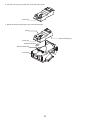
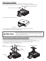
1. Attach the option lens FL-900 (H) to the projector.
(For details, refer to the Option Lens User's Manual (I).
2. Provide a worktable so that no force is applied to the option lens FL-900 (H).
Put cushioning materials on top of the worktable, and place the projector upside-down on the cushioning before
starting work.
Put the option lens FL-900 (H) in a location away from the worktable.
3. Use the two M4X10 screws (D) to attach the mount bracket (B) to the option lens FL-900 (H).
Tighteningtorque:0.98N•m(10kgf•cm)
4. Remove the two adjusters from the projector. 5. Insert the two collars (E) into the removed adjusters,
and mount to the projector.
Mounting the Brackets
Collar (E)
Option lens FL-900 (H)
Mount bracket (B)
Note the direction of
the arrow on mount
bracket (B).
M4x10 screws (D) (2 locations)
Adjuster Adjuster
Projector
Worktable
Adjuster
Collar
Option lens FL-900 (H)
Warning
■ Be extremely careful when performing the mounting work. An injury or other
accident can occur if the projector falls.

8
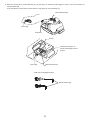
6. Use the hex key (F) to loosen the screw (Q) until it stops.
7. Mount the mount bracket (A) to the mount bracket (B).
Screw (Q)
Screw (Q)
(Hole)
Mount bracket (B)
Mount bracket (A)
Insertion direction
Protrusion

9
8. Move the screw (Q) of mount bracket (A) up and down as well as left and right to insert it into the protrusion of
mount bracket (B).
It can be easier to insert when viewing from the top (hole) of mount bracket (A).
Screw (Q)
Mount Bracket (B)
Mount bracket (B)
Side view of engaged section
Screw (Q) Mount bracket (A)
(Hole)
Protrusion
Insert the protrusion of
mount bracket (B) into this
section.

10
Use the four M6×16 hex-head screws (C) to attach the mount bracket (A) to the projector.
Tighten the M6×16 hex-head screws (C) in the order
①
to
④
.Tighteningtorque:1.96N•m(20kgf•cm)
When Using on a Tabletop
9. Return the projector to its original state.
10. Use the vertical and horizontal shift adjustment to adjust to the proper screen position.
11. Firmly tighten the screw (Q) until it is locked in place.
Warning
■ Whenever adjusting the vertical and horizontal shift, be sure to always loosen
the screw (Q). Adjusting the vertical and horizontal shift without loosening the
screw (Q) can damage the product.
■ After adjusting the vertical and horizontalshift,rmlyretightenthescrew(Q).
M6×16 hex-head screws (C)
M6×16 hex-head screws (C)
1. Use the four M6×16 hex-head screws (C) to mount the bracket (B) of the ceiling mount bracket (HAS-404U) to the
projector and mount bracket (A). Tighten the M6 × 16 hex-head screws (C) in the order
①
to
④
.
2. For the mounting work after this procedure, refer to the ceiling mount bracket (HAS-404U) user's manual.
3. Use the vertical and horizontal shift adjustment to adjust to the proper screen position.
4. Firmly tighten the screw (Q) until it is locked in place.
When Using the Ceiling Mount Bracket (HAS-404U)
M6×16
Hex-head screw (C)
HAS-404U
Bracket (B)
Mounting completedM6×16
Hex-head screw (C)
①
④
③
②
①
④
③
②
Screw (Q)
Screw (Q)
-
 1
1
-
 2
2
-
 3
3
-
 4
4
-
 5
5
-
 6
6
-
 7
7
-
 8
8
-
 9
9
-
 10
10


Ask a question and I''ll find the answer in the document
Finding information in a document is now easier with AI
Related papers
Other documents
-
Maxell FL920M User guide
-
-
-
Epson ELPMB30 User guide
-
NEC NP70CM User guide
-
Christie DWU951-Q Installation Information
-
Christie LWU601i-D Installation Information
-
-
Epson Epson Pro Cinema 4855WU User manual
-
Epson Pro G6050W User manual