Page is loading ...

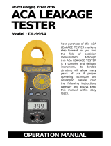
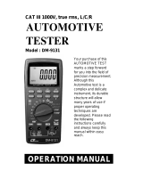
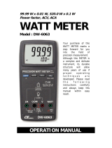
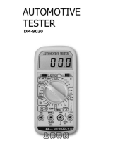
True RMS
AUTO RANGE
MULTIMETE
R
CAT III-1000 V cate
g
ory, Auto ran
g
e, REL, Capacitanc
e
Hz, Duty, ACV, ACA, DCV, DCA, Ohm
s

Caution Symbol
Caution :
* Risk of electric shock !
Caution :
* Do not apply the overload
voltage, current to the input
terminal !
* Remove test leads before open
the battery cover !
* Cleaning - Only use the dry
cloth to clean the plastic case !
Environment Conditions
* Installation Categories III-1000V.
* Pollution Degree 2.
* Altitude up to 2000 meters.
* Indoor use.
* Relative humidity 80% max.

TABLE OF CONTENTS
1. FEATURES................................................................
.
1
2. SPECIFICATIONS.....................................................
.
2
2-1 General Specifications.......................................... 2
2-2 Electrical Specifications........................................ 3
3. FRONT PANEL DESCRIPTION..................................... 6
4. PRECAUTIONS & PREPARATIONS FOR
MEASUREMENT......................................................... 8
5. MEASURING PROCEDURE..........................................
.
9
5-1 Symbols & Units of Display .................................9
5-2 DC voltage, AC voltage Measurement ................
.
10
5-3 Resistance Measurement.....................................10
5-4 DC current, AC current Measurement .................11
5-5 Continuity Check ...............................................
.
13
5-6 Diode Test ........................................................
.
13
5-7 Capacitance Measurement..................................
.
14
5-8 Frequency, DUTY Measurement...........................15
5-9 Relative Measurement........................................
.
16
5-10 Data Hold Operation.......................................... 16
6. MAINTENANCE..........................................................17
6-1 Replacement of Battery.......................................
.
17
6-2 Cleaning.............................................................
.
17
6-3 Replacement of Fuse...........................................
.
18
7. OPTIONAL ACCESSORIES & ADAPTERS .....................
.
19
8. THE ADDRESS OF AFTER SERVICE CENTER................20

1. FEATURES
* True RMS ACV, ACA measurement
* Meet IEC 1010 CAT III 1000 V safety requirement.
* Large LCD display with measurement unit.
* Multi function measurement. DCV, ACV, DCA, ACA,
Resistance, Capacitance, Frequency, Duty, Diode,
Continuity beeper.
* Data hold.
* Relative measurement.
* Auto range with manual range selection.
* When make the ACV, ACA measurement, it
also can measure the signal frequency, % duty at
the same time.
* 4000 counts A/D, high resolution.
* Both 10 A, mA, uA current are build fuse for safety
consideration.
* 10 M ohm impedance for voltage circuit.
* Operates from one DC 9V battery,
* Built-in overload protection for most ranges.
* Uses durable, long-lasting components, enclosed in
strong, light weight ABS-plastic housing.
* Full line optional adapters : Clamp adapter,
Tachometer adapter, Pressure adapter, Humidity
Adapter, Sound level adapter, Anemometer adapter,
Light adapter, EMF adapter.
1

2. SPECIFICATIONS
2-1 General Specification
s
Display 65 mm x 48 mm large LCD display
with bar graph indicator.
Measurement DCV, ACV, DCA, ACA, Resistance,
Capacitance, Frequency, Duty,
Diode, Continuity beeper.
A/D counts no. 4000 counts.
Range selection Auto range with manual range
selecting.
Special function Relative measurement, Data hold.
Data hold To freeze the display reading on the
LCD display.
Power On/Off Auto power of or manual power off.
management
@ Details please refer page 8
Relative To offset the measurement value.
measurement
Polarity Automatic Switching, " - " indicates
negative polarity.
Zero adjustment Automatic.
Sampling time Approx. 0.5 to 1 second.
Operating 0 to 50 (32 to 122 ),℃℉
Temp. & humidity Max. 80% RH.
Power supply 006 p dc 9V battery.
Power Approx. DC 1.7 mA.
consumption
2

Dimension 185 x 88 x 40 mm
( 7.3 x 3.5 x 1.6 inch )
Weight 350 g/0.77 LB.
Accessories Red and Black Test Leads
Included ( CAT III 1KV Test Leads )...... 1 Set
0.5 Amp Spare Fuse................ 1 PC
Instruction Manual..................
.
1 PC
Optional Full line adapters :
accessories ACA/DCA current adapter,
Tachometer adapter,
Humidity adapter, Pressure adapter,
Light adapter, EMF adapter,
Sound level adapter,
High voltage probe.
2-2 Electrical Specifications (23±5
)
℃
DC Voltage
Range 400.0 mV /4 V/40 V/400 V/1000 V
Resolution 0.1 mV /1 mV /10 mV /100m V/1 V
Accuracy ± (0.5%+2d )
Input impedance 10 M ohm.
Over load ± 500 DCV, 350 ACV - 400 mV range.
protection ± 1000 DCV, 1000 ACV - other ranges.
3

AC Voltage ( True RMS )
Range 4 V/40 V/400 V/1000 V
Resolution 1 mV /10 mV /100m V/1 V
Accuracy ± (1%+2d )
* Spec. are tested under 50/60 Hz.
Input impedance 10 M ohm.
Over load ± 1000 DCV, 1000 ACV - other ranges.
protection
AC Current ( True RMS )
DC Current
Range 10 A/400 mA/40 mA/4000 uA/400 uA
Resolution 10 mA/0.1 mA/0.01 mA/1 uA/0.1 uA
Accuracy 400 mA/40 mA/4000 uA/400 uA :
± (0.5%+2d )
10 A :
± (1.5%+2d )
* ACA spec. are tested under 50/60 Hz.
Over load 10A range : 10A fuse.
protection uA, mA range : 500 mA fuse.
Diode ( Forward voltage, VF )
Range 4 V DC.
Resolution 0.001 V.
Accuracy ± (0.5%+2d )
Capacitance
Range 40 nF/400 nF/4 uF/40 uF
Resolution 10 pF/0.1 nF/1 nF/10 nF
Accuracy < 2 nF : ± (3%+20d )
Others : ± (3%+1d )
4

Frequency
Range 4 Hz/40 Hz/400 Hz/4 KHz/40 KHz/
400 KHz/4 MHz
Resolution 0.001 Hz/0.01 Hz/0.1 Hz/0.001 KHz/0.01 KHz
0.1 KHz/0.001 MHz
Accuracy ± (0.5%+2d )
Sensitivity Min. 1.5 V rms, Max. 5 V rms.
Duty
Range 1 % to 99 %
Resolution 0.1 %
Accuracy ± 1% duty
Measuring signal Function switch set to " Hz " :
and level 2 Vp-p to 5 Vp-p,
square wave 10 KHz max.
Function switch set to "ACV", "ACA" :
50 Hz to 500 Hz
OHMS
Range 400/4 K/40 K/400 K/4 M/40 M ohm
Resolution 0.1/1/10/100/1 K/10 K ohm
Accuracy 400 ohm ± (0.5%+2d )
4K/40K/400K/4 M
40 M ± (2%+5d )
Over load ± 500 DCV, 350 ACV
protection
Continuity Beeper
Beeper will sound if measured resistance less than 20 ohm.
Remark :
* Spec. tested under the environment RF Field Strength less
than 3 V/M & frequency less than the 30 MHz only.
5

3. FRONT PANEL DESCRIPTION
Fig. 1
6

Fig. 1
3-1 Display
3-2 HOLD button
3-3 Hz/DUTY button
3-4 REL button
3-5 DCA/ACA button
3-6 RANGE button
3-7 Ohm/Diode/Buzzer button
3-8 Function rotary switch
3-9 10A input terminal
3-10 mA/uA input terminal
3-11 COM input terminal
3-12 Voltage/Ohm/Cap./Hz input terminal
3-13 Battery compartment/Cover
3-14 Stand
7

4. PRECAUTIONS & PREPARATIONS
FOR MEASUREMENT
1)Ensure that the 006 DC 9V battery are connected with
the right polarity and placed in the battery compartment
correctly.
2)Place the Red & Black Test Leads into the proper input
terminal before making measurement.
3)Remove either of the test leads from the circuit when
changing the measurement range.
4)Except operate the " Data Hold " function, it should
cancel the " Data Hold " function, otherwise the display
reading will freeze permanently.
5)Do not exceed the maximum rated voltage and current to
the input terminal.
6)Always switching the " Function Rotary Switch " to the
" Off " position when the instrument is not operation.
7)Remove the battery if the instrument is not to be used in
a long period of time.
8)For safety consideration, when change the new test
leads, it should use the replace test leads that already
approval of " CATIII-1000 V " at least.
9)Power On/Off management :
a. When not use the meter, should rotate the
" Function rotary switch " ( 3-8, Fig. 1 ) to the " OFF "
position.
b. During the measurement, after 30 minutes the meter
will auto power off. If intend to power on again, it
should rotate the " Function switch " to " OFF "
position then set to the new desiring function position.
8

5. MEASURING PROCEDURE
5-1 Symbols & units of display
Symbols Descriptions
Units
AUTO Appears when selecting " Automatic range " mode.
Appears when selecting DC mode.
( DC voltage or DC current )
Appears when selecting AC mode.
( AC voltage or AC current )
HOLD Appears when the " Data hold " function is operated.
REL Appears when the " Relative " function is operated.
Battery voltage is already under the low condition.
Appears when the " Continuity beeper " is operated.
mV, V Units for voltage measurements.
uA,mA,A Units for " Current " measurement.
Ω ,KΩ ,MΩ Units for resistance measurements.
nF,uF Units for " Capacitance " measurement.
Hz,KHz,MHz Units for " Frequency " measurement.
% Duty
Appears when the " Diode " function is operated.
- Appears when measuring a DCV or DCA value
is negative.
OL Over range indicator
9

5-2 DC Voltage, AC voltage Measurement
1)Connect BLACK test lead into " COM " terminal ( 3-11,
Fig. 1 ).
2)Connect RED test lead into " V " terminal ( 3-12, Fig. 1 ).
3)a. Select the " Function rotary switch " ( 3-8, Fig. 1 ) to
the " ACV" position for ACV measurement.
b. Select the " Function rotary switch " ( 3-8, Fig. 1 ) to
the " DC V " position for DCV ( 4V/40V/400V/1000 V )
measurement.
c. Select the " Function rotary switch " ( 3-8, Fig. 1 ) to
the " DC mV " position for DC mV ( 400 DC mV, one
range only ) measurement.
4)When LCD show the " AUTO " marker, the meter is
under the " auto range " mode. Meter will select the
suitable measurement range automatically.
* Under the operation of " auto range " mode, push the
" Range button " ( 3-6, Fig. 1 ) once will execute the
" Manual Range " mode and hold the range, the " AUTO "
marker will be disappeared.
* Under the manual range operation, push the " Range
button " ( 3-6 Fig. 1 ) > 2 seconds, will return to auto
range operation, the " AUTO " marker will present on
the LCD again.
5-3 Resistance Measurement
1)Connect BLACK test lead into " COM " terminal ( 3-11,
Fig. 1 ).
2)Connect RED test lead into " Ω " terminal ( 3-12, Fig. 1 ).
3)Select the " Function rotary switch " ( 3-8, Fig. 1 ) to
the " Ω " position.
10

4)When LCD show the " AUTO " marker, the meter is
under the " auto range " mode. Meter will select the
suitable measurement range automatically.
* Under the operation of " auto range " mode, push the
" Range button " ( 3-6, Fig. 1 ) once will execute the
" Manual Range " mode and hold the range, the " AUTO "
marker will be disappeared.
* Under the manual range operation, push the " Range
button " ( 3-6 Fig. 1 ) > 2 seconds, will return to auto
range operation, the " AUTO " marker will present on
the LCD again.
5-4 DC Current, AC Current Measurement
mA : 400 mA range, 40 mA range.
uA : 4000 uA range, 400 uA range.
1)Connect BLACK test lead into " COM " terminal ( 3-11,
Fig. 1 ).
2)For the " mA, uA " measurement, connect RED
test lead into " mA uA " terminal ( 3-10, Fig. 1 ).
For the " 10 A " current measurement, connect RED
test lead into " A " terminal ( 3-9, Fig. 1 ).
Open the circuit in which current is to b
e
measured. Now securely connect test leads i
n
series with the load in which the current is b
e
measured.
11

3)a. For the " uA " measurement ( 400 uA, 4000 uA ),
select the " Function rotary switch " ( 3-8, Fig. 1 )
to " uA " position.
b. For the " mA " measurement ( 40 mA, 400 mA ),
select the " Function rotary switch " ( 3-8, Fig. 1 )
to " mA " position.
c. For the " 10 A " measurement, select the " Function
rotary switch " ( 3-8, Fig. 1 ) to " A " position.
4)Push the " DCA/ACA button " ( 3-5, Fig. 1 ) to select the
" ACA " or " DCA " measurement,
The ACA measurement display will show AC.
The DCA measurement display will show DC.
5)When LCD show the " AUTO " marker, the meter is
under the " auto range " mode. Meter will select the
suitable measurement range automatically.
6)When LCD show the " AUTO " marker, the meter is
under the " auto range " mode. Meter will select the
suitable measurement range automatically.
* Under the operation of " auto range " mode, push
the " Range button " ( 3-6, Fig. 1 ) once will
execute the " Manual Range " mode and hold the
range, the " AUTO " marker will be disappeared.
* Under the manual range operation, push the "
Range button " ( 3-6 Fig. 1 ) > 2 seconds, will return
to auto range operation, the " AUTO " marker will
present on the LCD again.
12

5-5 Continuity Chec
k
1)Connect BLACK test lead into " COM " terminal ( 3-11,
Fig. 1 ).
2)Connect RED test lead into " Ω " terminal ( 3-12, Fig. 1 ).
3)Select the " Function rotary switch " ( 3-8, Fig. 1 ) to
the " " position, push the
" Ohm/Diode/Buzzer Button " ( 3-7, Fig. 1 ) for display
show " ".
4)when the resistance value is less than 20 ohm, the
beeper sound will be generated.
5-6 Diode Tes
t
1)Connect BLACK test lead into " COM " terminal ( 3-11,
Fig. 1 ).
2)Connect RED test lead into " Ω " terminal ( 3-12, Fig. 1 ).
3)Select the " Function rotary switch " ( 3-8, Fig. 1 ) to
" Ohm/Diode/Buzzer Button " ( 3-7, Fig. 1 ) for display
show " ".
4)a. When connected with polarity as shown in Fig. 2, a
forward current flow is established and the approx.
Diode Forward Voltage (VF) value in volt will
appears on the display reading. If the diode under
test is defective, " .000 " or near " .000 " value
( short circuit ) or " .OL " ( open circuit ) will be
displayed.
Fig. 2
13

b. When connected as shown in Fig. 3, a reverse check
on the diode is made. If the diode under test is
good, " .OL " will be displayed. If the diode under
test is defective, " .000 " or other numbers will be
displayed. Proper diode testing should include both
steps a. and b. above.
Fig. 3
5-7 Capacitance Measurement
1)Connect BLACK test lead into " COM " terminal ( 3-11,
Fig. 1 ).
2)Connect RED test lead into " " terminal ( 3-12, Fig. 1 ).
3)Select the " Function rotary switch " ( 3-8, Fig. 1 ) to
the " " position.
14

4)Zero adjustment :
Due to the consideration of the existing " stray
capacitance " of the internal circuit board or the test
alligators. For the 40 nF & 400 nF range, it should to
make the zero adjustment procedures before make the
measurement first. Open the input terminal & not
connecting the measured capacitor, push the " REL.
Button " ( 3-4, Fig. 1 ), the display will show zero value.
Then connect the measuring capacitor again & make the
measurement following.
5)For the capacitance measurement, the meter is always
under the " auto range " mode., it will select the suitable
measurement range automatically.
5-8 Frequency, Duty Measurement
Frequenc
y
1)Connect BLACK test lead into " COM " terminal ( 3-11,
Fig. 1 ).
2)Connect RED test lead into " V " terminal ( 3-12, Fig. 1 ).
3)Select the " Function rotary switch " ( 3-8, Fig. 1 ) to the
" Hz " position then push the " Hz/DUTY Button " ( 3-3,
Fig. 1 ) for display show " Hz " .
4)For the FREQUENCY measurement, the meter is always
under the " auto range " mode, it will select the suitable
measurement range automatically.
DUT
Y
A
ll the measuring procedures are same as above
Frequency measurement except push the " Hz/DUTY "
( 3-3, Fig. 1 ) for display show " % ".
15

Remark
:
Under the ACV measurement ( 5-2 ) or AC
A
measurement ( 5-4 ), if push the " Hz/DUT
Y
Button " ( 3-6, Fig. 1 ) once a while , will als
o
can measure frequency value or DUTY value o
f
the measured ACV or ACA.
5-9 Relative Measuremen
t
1)During the measurement, the circuit will memorize the
last measured values if push the " REL. Button " ( 3-4,
Fig. 1 ) at once, then LCD will show zero value & a "
REL " indicator.
2)The input measured values will deduct last measured
values " automatically, then show those new value on
the display.
3)It will cancel the relative measurement function i
f
push the REL. button at once again, at same time the
" REL " marker will disappear.
5-10 Data Hold Operatio
n
1) During the measurement, pushing the " Hold button "
( 3-2, Fig. 1 ) once a while will freeze the measured value
& the LCD will indicate " HOLD " symbol.
2)Push the " Hold Button " again to cancel the data hold
function.
16

6. MAINTENANCE
Caution :
Remove test leads before
opening the battery cover !
6-1 Battery replacement
1)When the LCD display showing the mark of " ",
it is necessary to replace the battery, However
in-spec. measurement may still be made for several
hours after " Low battery indicator " appears before
the instrument become inaccurate.
2)Open the screw of " Battery Cover " ( 3-13, Fig. 1 ) by
loosing the screws, then
move the battery.
3)Replace with DC 9V battery ( 006 P ) and reinstate the
cover.
6-2 Cleaning
Caution :
Cleaning - Only use
the dry cloth to clean
the plastic case !
17
/