Page is loading ...

INSULATION
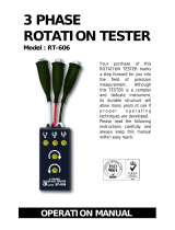
TESTE R
Model : AM-2002
Your purchase of this INSULATION TESTER marks a step
forward for you into the field of precision measurement.
Although this INSULAT ION T ESTER is a complex and delicate
instrument, its durable structur e developed. Please read the
following instructions carefully and always keep this manual
within easy reach.
OPERATION MANUAL
www.tmatlantic.com

Caution Symbol
Caution :
* Risk of electric shock !
Caution :
* Do not touch the input terminals
& the test lead's pins during the
measurements.
* Mega ohm range, do not appl
y
external voltage to input
terminals at any time.
* ACV & ohms range, do not appl
y
the overload voltage to the input
terminals !
* Remove test leads before open
the battery cover !
* Cleaning - Only use the dr
y
cloth to clean the plastic case !
Environment Conditions
* Installation categories III .
* Pollution Degree 2.
* Altitude up to 2000 meters.
* Indoor use.
* Relative humidity 80% max.

TABLE OF CONTENTS
1. FEATURES............................................................... 1
2. SPECIFICATIONS.....................................................
.
1
2-1 General Specifications......................................... 1
2-2 Electrical Specifications....................................... 3
3. FRONT PANEL DESCRIPTION.................................... 4
3-1 Display.............................................................
.
4
3-2 Function/Range Switch...................................... 4
3-3 Power Lock/Manual(off) Switch..........................
.
4
3-4 Test Button....................................................... 4
3-5 Input Terminal.................................................. 4
3-6 Battery Cover/Compartment............................... 4
4. PRECAUTION & PREPARATIONS FOR
MEASUREMENTS............................................................
.
5
5. MEASURING PROCEDURE......................................... 5
5-1 OHMS Measurement (Continuous Check)............
.
5
5-2 Mega OHM Measurement(Insulation
Measurement)................................................ 6
5-3 ACV Measurement............................................. 6
5-4 Power Lock/Manual(off) Switch..........................
.
7
6 MEASURING CONSIDERATION FOR
Mega OHM TESTING................................................
.
7
7. BATTERY REPLACEMENT..........................................
.
8
8.
T
HE ADDRESS OF AFTER SERVICE CENTER............... 9

1. FEATURES
* Digital display, easy and correct read-out.
* Multi function for insulation measurement of 200 M
ohm(100V) 200 M ohm(250V), 200 M ohm(500V),
1000 M ohm(1000V).
* Build in the ACV & OHM measurement function.
* Precision 200ohm range easy for measuring low
resistance such as motor windings, relay coils etc.
* A continuity beeper is equipped in 200 ohm range.
* Insulation measurement with high drive current,
2.8 mA short circuit current.
* 18mm (0.7") large LCD display.
* Battery operating easily to carry with user.
* LCD display allows clear read-out even at bright place.
* LSI-circuit provides high reliability and durability.
* Built-in over-input and low battery indication.
* Overload protection for each range.
* Automatic zero adjust & automatic circuit discharge.
* Durable & portable housing case with the front protective
cover.
2. SPECIFICATIONS
2-1 General Specifications
Display 18mm (0.7") LCD (Liquid Crystal Display),
Max. indication 1999.
Measurement Insulation 200M ohm/100V
200M ohm/250V
200M ohm/500V
1000M ohm/1000V.
ACV 600 ACV
OHMS 200 ohm, continuity beeper.
1

Sampling Time 0.4 second.
Mega ohm Max. approx. 2.5 second.
Respond Time
Zero Adjustment Automatic adjustment.
Over-input Indication of "1" .
Operating Temp. 0 to 50 (0 to 122 )℃℉
Operating Less than 80% R.H.
Humidity
Power Supply DC 9V, 1.5V AA(UM-3) battery x 6 PCs.
Alkaline or heavy duty battery.
Power Approx. 100 mA (1000M ohm/1000V range).
Consumption Approx. 28 mA (200 M ohm/500V range).
Approx. 28 mA (200 M ohm/250V range).
Approx. 13 mA (200 M ohm/100V range).
Approx. 10 mA (200 ohm/OHMS range).
Approx. 10 mA (600 ACV/ACV range).
Dimension 160 x 120 x 85 mm (6.3 x 4.7 x 3.3 inch),
with housing front cover.
Weight 575 g (1.3 LB).
Standard Instruction Manual .................1 PC.
Accessories Alligator Clips, AL-03S.............1 pair
2

2-2 Electrical Specifications (23± 5 )℃
Mega ohm
Range Accuracy Resolution Test Voltage
200 M ohm(100V) ± (3%+1d) 0.1 M ohm 100 V (+ 5%)
500 K ohm≧
200 M ohm(250V) ± (3%+1d) 0.1 M ohm 250 V (+ 5%)
500 K ohm≧
200 M ohm(500V) ± (3%+1d) 0.1 M ohm 500 V (+ 5%)
500 K ohm≧
1000 M ohm(1000V) ± (3%+1d) 1 M ohm 1000 V (+ 5%)
10 M ohm≧
* Input terminal Short circuit current is > 2.55 mA.
OHMS
Range Accuracy Resolution Open Circuit
Voltage
200 ohm ± (1%+1d) 0.1 ohm Approx. 3 V
* Overload Circuit Protection AC/DC 500V (within 20 sec)
AC VOLTAGE
RANGE Accuracy Resolution Input
Impedance
600 ACV ± (1%+2d) 1 ACV 4.5 M ohm
* Overload Circuit Protection 600 ACV
3

2. FRONT PANEL DESCRIPTION
Fig. 1
3-1 Display
3-2 Function/Range Switch
3-3 Power Lock/Manual(off) Switch
3-4 Test Button
3-5 Input Terminal
3-6 Battery Cover/Compartment
4

4. PRECAUTION & PREPARATIONS
FOR MEASUREMENTS
1. Remove the power from the circuit when making the
measurement. If any voltage is present in the testing
circuit, then an erroneous reading will result.
2. Ensure that the batteries (6 x 1.5 V AA battery) is
connected correctly the right position into the battery
compartment.
3. Rotate the "Function/Range Switch" (3-2, Fig. 1) to the
right position before making measurement.
4. Slide the "Power Lock/Manual(off) Switch" (3-3, Fig. 1)
to the off position if the meter not be used.
5. MEASURING PROCEDURE
5-1 OHMS Measurement (Continuous Check)
* Do not apply the external voltage
to the input terminals !
1. Connect the RED test plug into "ohm terminal"(3-5,
Fig. 1)
2. Connect the BLACK test plug into "COM terminal"(3-5,
Fig. 1)
3. Rotate the "Function/Range Switch"(3-2, Fig. 1) to the
"200 OHM" position.
4. Connect test alligator clips into circuit under test.
5.
Push the "Test Button"(3-4, Fig. 1) for measurement.
Remark :
A continuity beeper is equipped. If the measured resistance
< approx. 50 ohm, the beeper sounds will be generated.
5

5-2 Mega OHM Measurement(Insulation
Measurement)
* Do not touch the input terminals & the test
lead's pins during the measurements.
* Do not apply external voltage to input terminals
at any time.
1. Connect the RED test plug into "Hi terminal"(3-5,
Fig. 1)
2. Connect the BLACK test plug into "Lo terminal"(3-5,
Fig. 1)
3. Rotate the "Function/Range Switch"(3-2, Fig. 1) to the
"200M ohm/100V", "200M ohm/250V", "200M ohm/500V"
or "1000M ohm/1000V" position according the user's
requirement.
4. Connect the test ALLIGATOR CLIPS into the circuit
under test.
5.
Push the "Test Button"(3-4, Fig. 1) for measurement.
5-3 ACV Measurement
* Do not apply the overload voltage
to the input terminals !
1. Connect the RED test plug into "ACV terminal"(3-5, Fig. 1)
2. Connect the BLACK test plug into "COM terminal"(3-5,
Fig. 1)
3. Rotate the "Function/Range Switch"(3-2, Fig. 1) to the
"600 ACV" position.
6

4. Connect test alligator clips into circuit under test.
5. Push the "Test Button"(3-4, Fig. 1) for measurement.
5-4 Power Lock/Manual(off) Switch
Typically, when make the general measurement, always slide
the "Power Lock/Manual(off) Switch"(3-3, Fig. 1) to the
MANUAL(off) position. Then push the "Test Button" will
power on the meter until release the "Test Button"(3-4,
Fig. 1). However if user intend to power on the meter
permanently & making the measurement continuously, then
it should to slide the "Power Lock/Manual(off)
Switch"(3-3, Fig. 1) to the POWER LOCK position.
Attention :
When the measurement the impedance
( resistance ) value less than 1 Mega-
ohm, the period time of " Power Lock
ON " ( power ON permanently ) should
less than 5 minutes, otherwise the
internal circuit may will be overheated.
6. MEASURING CONSIDERATION
FOR Mega OHM TESTING
1. The amount of time during which the test voltage applied
will also affect the reading. With good insulation, the
measured value of insulation resistance will slowly
increase is applied typically. This is due to dielectric
absorption effect of the applied DC voltage on the bulk
insulation resistance.
7

2. Measurements made in a humid environment will result
in lower insulation resistance values than a dry environment.
7. BATTERY REPLACEMENT
* Remove test leads before open the battery
cover !
* Risk of electric shock !
1. When the upper left corner of LCD display show "BAT".
It is necessary to replace the battery. However in-spec
measurement may still be made for several hours after
LOW BATTERY INDICATOR appears before the
instrument becomes inaccurate .
2. Loose the screws that on the battery cover(3-6, Fig. 1).
Slide the battery cover & remove the battery.
3. Replace with 6 x 1.5V AA(UM-3) battery and reinstate
the cover.
8

8. THE ADDRESS OF AFTER SERVICE
CENTER
9
/