Sanwa PC7000 User manual

Category
Multimeters
Type
User manual
PC7000
DIGITAL MULTIMETER
INSTRUCTION MANUAL
Table of Contents
[1] SAFETY PRECAUTIONS
1-1 Explanation of Warning Symbols ………………………… 1
1-2 Warning Instructions for Safe Use ………………………… 2
1-3 Overload Protection ………………………………………… 3
[2] APPLICATIONS AND FEATURES
2-1 Applications ………………………………………………… 4
2-2 Features ……………………………………………………… 4
[3] Parts Identification
3-1 Multimeter and Test Leads ………………………………… 5
3-2 Display ……………………………………………………… 7
[4] DESCRIPTION OF FUNCTIONS
4-1 Power Switch/Function Selector …………………………… 8
4-2 Auto Power Saving ………………………………………… 8
4-3 Low Battery Indication ……………………………………… 9
4-4 Measuring Function Selection …………………………… 9
4-5 500000-count Display Mode …………………………… 10
4-6 Range Hold ……………………………………………… 11
4-7 Data Hold ………………………………………………… 11
4-8 Beeper Control …………………………………………… 11
4-9 PC (Personal Computer) Interface ……………………… 12
4-10 Test Leads Improper Connection Warning …………… 13
4-11 Crest capture mode (Sampling time: 0.8ms) …13
4-12 MAX/MIN/AVG Recording Mode ………………………… 13
4-13 Relative Measurement …………………………………… 14
4-14 Back Light ………………………………………………… 14
4-15 Terms ……………………………………………………… 14
[5] Measuring procedure
5-1 Pre-operational Check …………………………………… 16
5-2 Variable Frequency Drive (VFD)
AC Voltage (
)/Frequency (Hz) Measurement ……… 18
5-3 AC Voltage (
), Decibel (dBm)/Frequency (Hz)
Measurement ……………………………………………… 21
5-4 DC voltage (
)/AC Voltage ( )/
DC+AC Voltage (
) Measurement …………………… 24
5-5 DC Voltage (m )/AC Voltage ( m )/
DC+AC Voltage (m
), Logic-Level Frequency ( Hz)
and Duty Cycle (
D%) Measurement ……………… 27
5-6 AC Voltage ( m
), Decibel (dBm)/Frequency (Hz)
Measurement …………………………………………………31
 5HVLVWDQFH0HDVXUHPHQW&RQWLQXLW\&KHFN
),
and Conductance (nS) Measurement ………………… 34
5-8 Temperature Measurement ……………………………… 37
5-9 Capacitance (
) Measurement, Diode ( ) Test ……… 39
5-10 DC Current (
)/AC Current (
)/DC+AC Current (
),
AC Current (
)/ Frequency (Hz),
and %4
Measurement ………………………… 43
5-11 Measurements with Separately Available Accessories 52
[6] MAINTENANCE
6-1 Simple Examination ……………………………………… 56
6-2 Calibration ………………………………………………… 56
6-3 Battery and Fuse Replacement ………………………… 57
6-4 Storage …………………………………………………… 58
[7] AFTER-SALE SERVICE
7-1 Warranty and Provision ………………………………… 59
7-2 Repair ……………………………………………………… 59
7-3 SANWA web site ………………………………………… 60
[8] SPECIFICATIONS
8-1 General Specifications …………………………………… 61
8-2 Measuring Range and Accuracy ……………………… 63
[1] SAFETY PRECAUTIONS
*Before use, read the following safety precautions.
This instruction manual explains how to use your digital multimeter
PC7000. Before using, read through this manual to reduce the risk
of fire , electric shock, and/or injury. And save it together with the
product so that you can refer to the manual as necessary.
Use the instrument only as specified in this manual or the protection
provided by the instrument may be impaired.
The instructions given under the headings of "
WARNING" and
must be followed to prevent accidental burn andelectric shock.
1-1 Explanation of Warning Symbols
The meanings of the symbols used in this manual and attached to
the product are as follows.
:Extremely-important instructions for safe use
WARNING identifies conditions and actions that could result in
accidental burn and electric shock.
CAUTION identifies conditions and actions that could cause
damage the instrument.
:Do not touch! Possible high voltage.
:Ground :Diode Hz:Frequency
:Fuse :Beep
Logic-Level Frequency
Direct Current(DC)
:Capacitor :Duty Cycle
:Alternate Current (AC) : Nano-Siemens (Conductance)
Resistance
:Temperature :Back light
Double Insulation or Reinforced
1-2 Warning Instructions for Safe Use
1. Do not use the instrument if the meter or test leads look damaged.
2. Be sure to use the specified fuse.
Neither use unspecified fuse nor short-circuit the fuse holder.
3. Do not apply higher voltage or current than the max. ratings by each
function. (See 1-3)
4. Use caution when working with voltages above 33 V ac rms, 46.7 V ac
peak, or 70 V dc. These voltages pose a shock hazard.
5. Do not use the meter to measure lines that may have inductive voltage
or surge voltage (e.g. motors) because the input voltage may exceed the
maximum rated voltage.
6. Never operate the meter with the case or battery lid removed.
7. Remove test leads from the meter before opening the meter case for
replacing the battery or fuse.
8. Never attempt to repair or modify the instrument, except for battery and fuse
replacement.
9. Do not use any unspecified type of test leads.
10. Keep your fingers behind the finger guards of the test leads while
measurement.
11. Connect the common test lead (Black) before you connect the live test lead
(Red). Disconnect the live test lead first.
12. Make sure the function, range, and measuring terminals are properly set.
13. Do not switch the function, range, or the plugs to another while
measurement.
14. Do not operate the meter when it is wet or with wet hands.
WARNING
Incorrect measurement may be performed in a ferromagnetic or
intense electric field near transformers, high-current circuits, and
radio equipments.
CAUTION
1-3 Overload Protection
Function
Measuring
Terminal
Max. Rated Input Overload Protection
and
COM
1000V dc/ac 1050V rms, 1450V peak
5V dc/ac
600Vrms
Do not apply
any voltage or
current.
50mV dc
mAµA
and
COM
600mA dc/ac
Do not apply
any voltage.
0.63A/500V Fuse
Breaking capacity: 50kA
and
COM
10A dc/ac
Do not apply
any voltage.
12.5A/500V Fuse
Breaking capacity: 20kA
[2] APPLICATIONS AND FEATURES
2-1 Applications
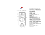
This instrument is a portable digital multimeter designed to
measure light electric circuits. The instrument offers not only
measurements for small communication equipments, home
electric appliances, output from a wall socket, and many batteries,
also circuit analyses with additional functions.
2-2 Features
 Compliant with IEC61010-1 CAT. 600V, CAT. 1000V, and safe
design using fuses with large number of breaking capacity.
 50000-count display (DCV, ACV, DCA, ACA, Ohm)
 500000-count display (DCV)
 99999-count display (Hz)
 Fast response display
(Numeric parts: 5 times/Sec. Bar graph part: 60 times/Sec.
where 50000-count display mode)
 Dual Display shows "Voltage or Current and its Frequency", and
"AC components and DC components of Voltage or Current"
 True RMS detection for alternate current (AC) (True RMS)
 DC+AC indications available
 Low-pass filter for Variable Frequency Drive (VFD) circuit
 dBm indication for decibel measurement
 Resolution: 0.001 mV for DCV, 0.01mV for ACV
 Frequency (Sensitivity selectable),
Wide capacitance range (0.01nF to 25.00mF)
 Automatically range selectable Crest Capture Mode
Sampling time: Approx. 0.8ms
 MAX/MIN/AVG recording mode with auto ranging
(Sampling rate: 20times/Sec. in the voltage or current function)
 Relative mode with auto ranging
 Back light to allow for easy visibility in low-lit area
 Temperature measurement
(K-type thermocouple: –50 to 1000 )
 PCLink7 (separately available software) allows you to download
logged data into your PC with USB optical communication unit
(KB-USB7)
[3] Parts Identification
3-1Multimeter and Test Leads
With the detachable test pin covers: CAT. III 600V
Without the detachable test pin covers: CAT. II 1000V
Light shielding magnet cap
Optical
communication
unit connector
Stand
Battery door
Holster
Finger guards
Plugs
Test probe (red)
Test probe (black)
Test leads TL-23a
Detachable test pin covers
Test pins
LCD display
Range hold button
G%PEXWWRQ
Select button
%DFNOLJKWEXWWRQ
Crest capture button
Relative button
EXWWRQ
MAX/MIN/AVG
recording button
Data hold button
Power/
Function selector
Common terminal
Measuring
terminal
Measuring terminal
for A
Measuring terminal
for mAµA
How to detach the light shielding magnet cap
Turn the light shielding magnet cap counterclockwise to detach.
An application of the light shielding magnet cap
Note:
Keep the light shielding magnet cap away from cellular phones,
analog watches, floppy disks, magnetic cards, magnetic tapes, and
magnetic tickets. Otherwise, the memorized information may be lost.
Attached
Magnetically attractable
material wall (e.g. steel)
DMM body
Attach the light shielding magnet cap
with side touched to the wall.
3-2 Display
Main display
Unit of readings for main display
Polar character for main display
Analog bar graph
Sub display
Unit of readings for sub display
Polar character for sub display
Low battery voltage indicator
Auto range mode indicator
Recording mode indicator
Data hold indicator
Crest capture mode indicator
Max/Min/Avg updating indicator
DC measurement indicator
AC measurement indicator
Low-pass filter operation indicator
Relative mode indicator
Continuity check indicator
[4] DESCRIPTION OF FUNCTIONS
4-1 Power Switch/Function Selector
Turn the switch to turn on/off the power and select a measuring
function. All segments of the LCD display will be turned on for 1
second after power-on, and then the meter will be ready to use.
Note:
The push buttons between the display and the function selector
work differently depending on how long you press. In this
manual, "press" means pressing momentary and "press for 1
sec. or more" means pressing longer.
4-2 Auto Power Saving
The Auto Power Saving mode turns the meter off automatically
after approximately 17 minutes of no activities. While the Auto
Power Saving mode, the following activities set the Auto Power
Saving back.
1) Function selector or push button operations
2) Non-OL readings in the function
Following activities disable the Auto Power Saving mode
automatically.
1) Crest capture mode or MAX/MIN/AVG recording mode is in
use
2) Data communication to your PC is in use
4-2-1 How to get back from the Auto Power Saving
Press the SELECT, RANGE HOLD, REL or HOLD button,
or disconnect the object to measure and turn the power switch
off and then back on, and select a function before connecting
the object.
4-2-2 How to disable the Auto Power Saving
Press the SELECT button while turning the meter power on.
Release the SELECT button after
is turned off. (All
segments of the display turn on after power-on.) Then the meter
will be ready to use.
Turn the power switch OFF and then back on to resume.
Note:
Even in the Auto Power Saving mode, approx. 70 µA will be
consumed. When in the auto power saving mode, intense light
like the direct sunlight into the optical communication unit on
the back of the DMM increases the consumption current. To
prevent unexpected battery wearing down, mount the attached
light shielding magnet cap on the optical comminucation unit
connector when not in use. Always turn the power switch to the
OFF position when the meter is not in use for a long time.
4-3 Low Battery Indication
Decreasing the internal battery voltage to approx. 7V due to
wearing down turns on the
indicator on the LCD display.
Replace the battery with new one when the indicator turns on.
Use under "Low Battery" may cause malfunctions.
4-4 Measuring Function Selection
At each position of the function selector, press SELECT button
( ) to select measuring functions as follows.
* Dual display: [Main display/Sub display]
[
/Hz ] [ Hz/ ]
[
/Hz ] [ dBm/Hz ] [ Hz/ ] [ /Hz ]
[
] [ / ] [ / ] [ ] …
[ m
] [ m / m ] [ m / m ] [ ]
[ D% ] [ m
] …
[ m
/Hz ] [ dBm/Hz ] [ Hz/m ] [ m /Hz ]
>@ [
] [ nS ] >@
[ C ] [ F ] ( C: , F:
o
F)
[
] [ ]
When a test lead is not connected to measuring terminal
,
[ m
/%4 20mA ] [ m
/ m
] [
/m
]
[ m
/Hz ] [ m
/%4 20mA ]
When a test lead is connected to terminal
,
[
] [
/
] [
/
] [
/Hz ] [
] …
[ µ
] [ µ
] [ µ
] [ µ
/Hz ] [ µ
]
Note:
The last selection of each function will be saved as power up
default for repeat measurement convenience.
4-5 500000-count display mode
Press the 500000 ( REL) button for 1 second or more to turn
the 500000-count display mode on. It is available to single display
DC Voltage function ranges. Measuring speed is reduced to 1.25
times per second. To turn the 500000-count display mode off,
press the 500000 ( REL) button for 1 sec. or more again, or
press SELECT button to change the display mode.
4-8 Beeper Control
Press the RANGE HOLD button while turning the meter power on
to disable the beeper. Release the RANGE HOLD button after
is turned off. (All segments of the display turn on right after power-
on.) Then the meter will be ready to use. Turn the power switch
OFF and then back on to resume.
Note:
The beeper for the continuity check and the plug improper
connection warning will not be disabled.
4-6 Range Hold
Press the RANGE HOLD button to select manual-ranging, and the
meter will remain in the range it was in. (
turns off.) In
the manual-ranging mode, press the button again to step through
the ranges. Select an appropriate range making sure units and
decimal point positions. To resume auto-ranging mode, press and
hold the button for 1 second or more.
Note:
Manual ranging mode is not available in the Hz functions.
4-7 Data Hold
Press HOLD button to freeze present reading for later view. (
indicator turns on.) Input fluctuation will not reflect on the indicated
value. Press the HOLD button again to disable the data hold
feature and go back to the normal measurement mode. (
indicator turns off.)
Note:
Function changes or functional operations will cancel the data hold
feature.
USB Optical Communication Unit
(KB-USB7)
Optical Communication Unit Connection
Note:
Intense light like the direct sunlight into the optical communication
unit on the back of the DMM increases the consumption current.
Mount the attached light shielding magnet cap on the optical
comminucation unit connector when not in use.
4-9 PC (Personal Computer) Interface
The instrument equips with an optical isolated interface port at the
meter back for data communication. KB-USB7, dedicated USB
optical communication unit (separately available), and PCLink7,
dedicated software, allow you to transfer real time readings and
internally logged data to your PC. For more information, see the
"HELP" for PCLink7 (PC linkage software).
4-10 Test Leads Improper Connection Warning
The meter beeps as well as displays InErr to warn the user
against possible damage to the meter due to test leads improper
connections to the
, or measuring jacks when
other function (like voltage function) is selected. (Temperature
measurement function is an exception.)
Note:
InErrwarning may be indicated due to weak battery even if
the test leads are connected properly.
4-11 Crest capture mode (Sampling time: 0.8ms)
Press the CAPTURE button to activate the crest (Instantaneous
Peak-Hold) mode to capture voltage or current signal duration
which is longer than 0.8ms.
and MAX indicator
turns on. The meter beeps when new MAX (maximum) or MIN
(minimum) reading is updated. Press the button to read the
MAX , MIN, and MAX-MIN (peak to peak) readings in sequence.
Press the button for 1 sec. or more to exit the crest mode. Auto-
ranging (up range) remains, and Auto Power Saving is disabled
automatically in this mode.
4-12 MAX/MIN/AVG Recording Mode
When this mode is activated, the reading update rate will be
increased to 20 times/sec. in the voltage measurement or
current measurement function, and the update rate in the other
function ranges will remain.
Press the REC button to activate the MAX/MIN/AVG recording
mode, and
, MAX, MIN, and AVG turn on. The meter
beeps when new MAX (maximum) or MIN (minimum) reading
is updated. Press the button to show the MAX , MIN, MAX-MIN
(peak to peak), and AVG readings in sequence. Press the button
for 1 sec. or more again to exit the MAX/MIN/AVG recording
mode. Auto-ranging remains, and Auto Power Saving is disabled
automatically in this mode.
4-13 Relative Measurement
Press the REL button to activate the relative measurement
mode and indicator turns on. The relative measurement
mode offsets the meter to display relative values against a
reference. The meter displays its readings subtracting the
reading at the moment the REL button is pressed. Press the
REL button again to exit the relative measurement mode.
This feature is available also while the MAX/MIN/AVG recording
mode.
4-14 Back Light
Press the SELECT button for 1 sec. or more to turn the backlight
on. (Automatically turns off after approx. 15sec.)
Press the SELECT button again for 1 sec. or more to turn the
backlight off.
4-15 Terms
Analog bar graph
The a nal og ba r graph p rov ide s a vis ual indication of
measurement like a traditional analog meter needle.
True RMS
True RMS is a term which identifies a DMM that responds
accurately to the effective RMS value regardless of the
waveforms such as square, sawtooth, triangle, pulse trains,
spikes, as well as distorted waveforms with the presence of
harmonics. This instrument employs the True-RMS (Root-Mean-
Square) detection.
Crest Factor
Crest Factor is the ratio of the Crest (instantaneous peak) value
divided by the True RMS value. Most common waveforms such
as sinusoidal wave and chopping wave have a relatively low
crest factor. A low duty cycle wave form like pulse string has
a high crest factor. For voltages and crest factors for typical
waveforms, see the table below. Please note that measurement
should be made under the crest factor below 3.
Input Waveform
0 to PEAK
Vrms
Average
Value
Crest
Factor
Form
Factor
Root Mean
Square Value
Vavg
Vp/Vrms
Vrms/Vavg
Sinusoidal
wave
Square
wave
Chopping
wave
Pulse
Vp
1. Do not use the instrument if the meter or test leads look
damaged.
2. Make sure the test leads and the fuse are not broken.
WARNING
Make sure the low battery indicator is off after power-on. Replace
the battery with new one if the indicator is on.
CAUTION
Perform pre-oparational check for safety.
(Inspection using continuity check)
[5] Measuring procedure
5-1 Pre-operational Check
Contact us for repair.
Meter/Test leads damaged?
Connect the red plug of the test lead to
measuring
terminal and the black one to the COM terminal.
Set the function selector to
.
Press the SELECT button to select the continuity check (
).
Short-circuit between the red and black test pins.
WXUQVRQ"
Beeper sounds?
Finished
Does not turn on.
Does not sound.
Turns on. Sounds
Looks OK
Damaged
*In the case nothing is displayed, check for the battery.
  • Page 1 1
  • Page 2 2
  • Page 3 3
  • Page 4 4
  • Page 5 5
  • Page 6 6
  • Page 7 7
  • Page 8 8
  • Page 9 9
  • Page 10 10
  • Page 11 11
  • Page 12 12
  • Page 13 13
  • Page 14 14
  • Page 15 15
  • Page 16 16
  • Page 17 17
  • Page 18 18
  • Page 19 19
  • Page 20 20
  • Page 21 21
  • Page 22 22
  • Page 23 23
  • Page 24 24
  • Page 25 25
  • Page 26 26
  • Page 27 27
  • Page 28 28
  • Page 29 29
  • Page 30 30
  • Page 31 31
  • Page 32 32
  • Page 33 33
  • Page 34 34
  • Page 35 35
  • Page 36 36
  • Page 37 37
  • Page 38 38
  • Page 39 39
  • Page 40 40
  • Page 41 41
  • Page 42 42
  • Page 43 43
  • Page 44 44
  • Page 45 45
  • Page 46 46
  • Page 47 47
  • Page 48 48
  • Page 49 49
  • Page 50 50
  • Page 51 51
  • Page 52 52
  • Page 53 53
  • Page 54 54
  • Page 55 55
  • Page 56 56
  • Page 57 57
  • Page 58 58
  • Page 59 59
  • Page 60 60
  • Page 61 61
  • Page 62 62
  • Page 63 63
  • Page 64 64
  • Page 65 65
  • Page 66 66
  • Page 67 67
  • Page 68 68
  • Page 69 69
  • Page 70 70
  • Page 71 71
  • Page 72 72
  • Page 73 73
  • Page 74 74

Sanwa PC7000 User manual

Category
Multimeters
Type
User manual

Ask a question and I''ll find the answer in the document

Finding information in a document is now easier with AI