Page is loading ...

Instruction Manual
Instruction Manual
For
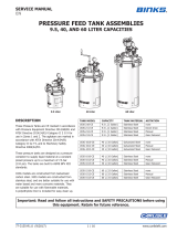
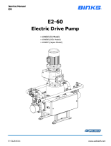
E2-15 AFP Electric Drive Pump
• Model 104125 (EU Model)
• Model 104135 (USA Model)
• Model 104134 (Japan Model)

Instruction Manual
Page 2 of 28 77-3227-R1.0

Instruction Manual
Page 3 of 28 77-3227-R1.0
Specification
Pump Nominal Stroke
50 mm (1.97 ins)
E2-15 Maximum Fluid Pressure
20 bar (290 psi)
E2-15 Nominal Flow Volume / Cycle
0.375 Litres (0.10 US Gall)
E2-15 Fluid Output @ 20 HZ (10 cycles/min)
3.75 Litres / min (1.0 US Gall / min)
E2-15 Fluid Output @ 80 HZ (40 cycles/min)
15.0 Litres / min (4.0 US Gall / min)
Fluid Inlet / Outlet Connections
1” Sanitary
Gearbox Ratio
56:1
Gearbox Oil Quantity (EP ISO VG 220 Mineral Oil)
(EU Model)
1.7 Litres ( 0.45 US Gall)
Gearbox Oil Quantity (SHC 630 Synthetic Oil)
(USA Model)
Litres ( US Gall)
AC Induction Electric Motor -EU Model
0.75 kW 4Pole 1400 RPM
(0.75 kW 4Pole 1400 RPM Japan Model)
400V 3PH 0.75 kW @ 50HZ
EEx d 11B T3
Rated 20 to 80 Hz (with thermisters)
AC Induction Electric Motor - USA Model
460V 3PH 1 Hp @ 60HZ
Class 1, Group D.
Rated 20 to 80 Hz (c/w thermostats)
Total Weight of Pump (inc electric motor)
80 Kg (176 Lb)
Max. Inlet Pressure
7 Bar (101 psi)

Instruction Manual
Page 4 of 28 77-3227-R1.0

Instruction Manual
Page 5 of 28 77-3227-R1.0

Instruction Manual
Page 6 of 28 77-3227-R1.0
Installation – General
The E2-15 AFP Pump Units are designed for location in Zone 1 Hazardous areas,
ATEX Category 2. Electrical connections must be in accordance with Local
regulations for installation in Hazardous areas.
It is recommended that a Local Control Box is positioned in close proximity to the
pump, as a convenient local Start / Stop facility and Junction box. The main Pump
Control Panel must be positioned within an Electrically Safe Area.
A Pressure switch (and/or Pressure relief valve) must be connected to the outlet
manifold port and set to stop the pump (or relieve the fluid pressure) in the event of
the system overpressure e.g. blocked paint filter. This is necessary to protect the
Pump mechanics from overload. An adapter to mount a pressure switch and
pressure sensor is available, see accessories.
It is recommended that the switch setting is set to 1 bar (14.5 psi) above the
maximum required pressure. The maximum Pressure setting the pressure switch
should be set to is 21 bar (305 psi).
The pressure switch must be fitted and functioning correctly before the pump is put
into use otherwise Pump warranty may be invalidated.
Attach suitable hoses (20 bar maximum working pressure) to the inlet and outlet
connections. E.g. 28 mm NB Inlet and 25 mm NB Outlet hose.
Secure the Pump assembly to the floor (or purpose designed support steelwork)
using the 4 off Ø10 mm holes in the base of the pump support frame.
Ensure adequate air space around the Pump for maintenance and electric motor
cooling requirements.
Ensure the gearbox is filled with oil. (The gearbox is filled with the correct amount of
oil at the factory)

Instruction Manual
Page 7 of 28 77-3227-R1.0
Electric Motor
Electric Motors for hazardous areas are specially designed to comply with official
regulations concerning the risk of explosion. If improperly used, badly connected, or
altered no matter how minor, their reliability could be in doubt.
Standards relating to the connection and use of electrical apparatus in hazardous
areas must be taken into consideration. Only trained personnel familiar with these
standards should handle this type of apparatus.
The Pump Frame must be
wired to a suitable earth
ground to ensure that there is
no possibility of static build up

Instruction Manual
Page 8 of 28 77-3227-R1.0
Installation – Electrical
Inverter
The pump cycle rate and thus the fluid output is controlled by adjusting the motor
speed, this is achieved by changing the electrical frequency input to the motor
between the range of 20 and 80 Hz.
A suitable 3PH AC inverter must be used to control the motor speed,
Where the customer provides a suitable inverter then the following parameters are to
be used.
Important! The electric motor is certified for use in a hazardous area between
frequencies of 20 Hz an 80 Hz, therefore it is essential that this range cannot be
inadvertently exceeded by the operator as this will invalidate the certification
and use of the electric motor.
Required European Inverter Settings Value
Maximum Hz output 80 Hz
Minimum Hz output 20 Hz
Acceleration Ramp 5 Seconds
Deceleration Ramp 0.1 Seconds
Rated Motor Power 0.75 kW
Rated Motor Current 2 A
Rated Motor Voltage 400 V
Rated Motor speed 1440 RPM
Rated Motor Power Factor 0.81
Rated Motor Efficiency 78 %
Rated Motor Frequency 50 Hz
Application Criteria
In a general manner inverters can be connected directly to the power supply line
without line reactors. But in this case, ensure the following:
To prevent damage to the inverter and to ensure its expected life, minimum line
impedance that introduces a voltage drop of 1%, as a function of the motor load,
should be used. If the line impedance (transformers + wirings) is lower than these
values, it is recommended to use line reactor.

Instruction Manual
Page 9 of 28 77-3227-R1.0
System Operation
Before starting: -
• Ensure all electrical and mechanical connections are correctly made.
• All required interlocks are tested and operational.
• Suitable material for pumping is available at the suction hose.
• The outlet connection is not blocked or isolated by any valves.
• Check the gearbox oil level, top up as necessary with the correct grade (see
maintenance section) and that the gearbox ventilator is fitted.
• Cam rotation must be clockwise.
Set the pump speed to the minimum frequency 20 HZ and. Inspect for any leaks.
After 3-4 minutes run the pump at 60-80 Hz to remove any air from the inlet & outlet
pipework. Run pump for 10 minutes. Reduce speed to 30 Hz and slowly increase
pressures, checking for leaks, after testing set pump to open or closed loop as
required.
Set the pump cycle rate to achieve the required paint volume and then adjust the
system back pressure regulator to achieve the desired system fluid pressure.
Refer to Fluid Output Table for comparison of fluid output relative to Inverter
frequency and Pump cycle rate.
The return line ‘back pressure’ regulator responds to the changes in system fluid flow
demand, (due to variable paint usage) by dynamically adjusting the paint flow rate
returning to the system paint tank, thus maintaining the set pressure.
Motor Speed Fluid Output Table
Motor
Speed
HZ
Pump Speed
Cycles/min
Fluid Flow Rate
Litres/min
Fluid Flow Rate US
Gall/min
20
10.0
3.75
1.0
25
12.5
4.69
1.25
30
15.0
5.62
1.5
35
17.5
6.
56
1.75
40
20.0
7.50
2.0
45
22.5
8.44
2.25
50
25.0
9.37
2.5
55
27.5
10.31
2.75
60
30.0
11.25
3.0
65
32.5
12.19
3.25
70
35.0
13.12
3.5
75
37.5
14.06
3.75
80
40.0
15.00
4
.0

Instruction Manual
Page 10 of 28 77-3227-R1.0
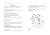
Parts List – E2-15 AFP PUMP ASSEMBLY
ITEM PART No DESCRIPTION QTY REMARKS
1 E2-15AFP PUMP 1
2 193089 GEARBOX (EU) 1
2 193090 GEARBOX (USA) 1
2 193091 GEARBOX (JAPAN) 1
3 192877 0.75Kw ELECTRIC MOTOR (EU) 1
3 193092 0.75KW ELECTRIC MOTOR (JAPAN) 1
3 193093 1 HP ELECTRIC MOTOR (USA) 1 BALDOR
3 193118 1 HP ELECTRIC MOTOR (USA) 1 MARATHON

Instruction Manual
Page 11 of 28 77-3227-R1.0

Instruction Manual
Parts List – E2-15 AFP PUMP ASSEMBLY
ITEM PART No DESCRIPTION QTY REMARKS
10 207-12333 BOTTLE 2
11 165108 M8 SPRING WASHER 4
12 164474 M8 x 16 TORX SCREW (ST ST) 4
13 163144 M8 HEXAGON NUT 4
14 165123 Ø10 SPRING WASHER (STST) 8
15 165134 Ø8 Washer 4
16 165947 M10 x 35 CAP HD SCREW 8
17 192009 1 & 1 1/2 SANITARY CLAMP 12
18 192206 1 SANITARY GASKET PTFE 12
19 192440 Ø10.4 'O' RING (COVER) 4
20 192485 M8 WASHER (NYLON) 4
21 192866 COVER 2
22 194109 1" SANITARY ELBOW 6
23 194182 BOTTLE ADAPTOR 2
24 194186 MANIFOLD 2
25 194188 E2-15 AFP FLUID SECTION ASSY 2
26 194189 E2-15 AFP MECHANICAL ASSY 1

Instruction Manual
Page 13 of 28 77-3227-R1.0

Instruction Manual
Page 14 of 28 77-3227-R1.0
Parts List – 194189 MECHANICAL ASSEMBLY
ITEM PART No DESCRIPTION QTY REMARKS
30 160524 CARRIAGE SPRING 4
31 163161 M8 NYLOC NUT - STST 4
32 163921 M6 x 25 CAP HD SCREW 6
33 164471 M10 x 20 CAP HD SCREW 4
34 165044 M12 SPRING WASHER 4
35 165100 M16 SPRING WASHER 2
36 165108 M8 SPRING WASHER 4
37 165123 Ø10 SPRING WASHER 4
38 165351 M12 x 50 HEX HEAD BOLT 4
39 165661 M8 x 20 - GRUBSCREW 4
40 165667 M8 x 50 GRUBSCREW 4
41 165958 M6 x 20 HEX HD SCREW 2
42 165959 M6 WASHER 2
43 177020 M8 MUDGUARD WASHER 4
44 177021 M8 x 20 BUTTON HEAD CAPSCREW 4
45 192400 SPRING RETAINING WASHER 4
46 192441 M16 EYE BOLT 2
47 192551 HEXAGON PLUG - 1/4 BSP 2
48 192650 1/8 x 45 GREASE NIPPLE 2
49 192661 1/8R - 6MM PUSH IN ELBOW 2
50 192668 SHAFT CLAMP ASSY 2
51 192849 CARRIAGE ASSEMBLY 2
52 192854 MAIN BODY MACHINING 1
53 192860 MOUNTING FRAME 2
54 192865 COVER SPACER 4
55 192869 LINEAR SPRING PIN 2
56 192870 GREASE BULKHEAD 2
57 192872 LINEAR BEARING ROD 2
58 192875 DRIVE SHAFT COUPLING 1
192876
spider
59 192878 8 x 7 x 30 KEY 1
60 192880 Ø6 GREASE HOSE 2
NOT SHOWN
61 193695 Ø30 SHAFT COUPLING SPACER 1
62 194198
E2-15 BELL HOUSING CAM
ASSEMBLY
1

Instruction Manual
Page 15 of 28 77-3227-R1.0
Parts List – 194198 BELL HOUSING CAM ASSEMBLY
ITEM PART No DESCRIPTION QTY REMARKS
65 162709 Ø30 x Ø42 x 7 SEAL 1
66 163960 M5 x 16 CAP HD SCREW 6
67 165558 M8 x 50 CAP HD SCREW 8
68 165972 M5 x 25 CAP HD SCREW 6
69 165974 M25 BEARING LOCKNUT 1
70 192650 1/8 x 45 GREASE NIPPLE 1
71 192703 M30 BEARING LOCKNUT 1
72 192850 CONSTANT VELOCITY CAM 1
73 192853 BELL HOUSING MACHINING 1
74 192855 TOP SHAFT 1
75 192856 BOTTOM SHAFT 1
76 192857 TOP BEARING CAP 1
77 192858 BOTTOM BEARING CAP 1
78 192859 BOTTOM BEARING HOUSING 1
79 192873 Ø30 x Ø72 x 30.2 BALL BEARING 1
80 192874 Ø25 x Ø52 ROLLER BEARING 1

Instruction Manual
Page 16 of 28 77-3227-R1.0
Parts List – 192849 CARRIAGE ASSEMBLY
ITEM PART No DESCRIPTION QTY REMARKS
85 162734 Ø41 x 1.78 SECTION 'O' RING 12
86 163159 M12 NYLOC NUT 1
87 165542 M6 x 12 CAP HD SCREW 2
88 166156 Ø46 EXTERNAL CIRCLIP 4
89 192392 Ø47 CAM FOLLOWER 1
90 192661 1/8R - 6MM PUSH IN ELBOW 1
91 192851 LINEAR BEARING HOUSING 2
92 192852 LINEAR BEARING CARRIAGE 1
93 192861 CARRIAGE ADAPTOR 1
94 192862 CAM FOLLOWER PIN 1
95 192863 FOLLOWER NUT WASHER 1
96 192871 Ø25 LINEAR BEARING 4
97 193112 9 X 12 X 14 LINEAR BEARING 2

Instruction Manual
Page 17 of 28 77-3227-R1.0

Instruction Manual
Page 18 of 28 77-3227-R1.0
Parts List – 194188 FLUID SECTION ASSEMBLY
ITEM PART No DESCRIPTION QTY REMARKS
100 41-4404 BALL CAGE 1
101 41-4415 PISTON BOLT SEAL 1
102 162844 PISTON SEAL 1
103 163921 M6 x 25 CAP HD SCREW 4
104 163952 M6 x 20 CAP HD SCREW 4
105 164031 1/2-20 X 1 HEX HD SCREW 1
106 165087 M6 SPRING WASHER 4
107 165108 M8 SPRING WASHER 4
108 165123 Ø10 SPRING WASHER 4
109 165947 M10 x 35 CAP HD SCREW 4
110 165990 M8 x 55 CAP HD SCREW 4
111 192382 Ø25.4 BALL 2
112 192712 O-RING Ø37.82 x 1.78 PTFE 5
113 192825 INLET CYLINDER 1
114 192827 OUTLET CHECK 1
115 192833 SEAT 2
116 193245 ¼" BRASS SILENCER 1
117 194105 CERAMIC PISTON 1
118 194178 OUTLET CYLINDER MACHINING 1
119 194179 INLET ADAPTOR MACHINING 1
120 194187 E2-15 AFP SHAFT & BELLOWS ASSY 1

Instruction Manual
Page 19 of 28 77-3227-R1.0
Parts List – 194187 SHAFT & BELLOWS ASSEMBLY
ITEM PART No DESCRIPTION QTY REMARKS
125
192374
RETAINING
NUT
1
126
192579
KNIFED BELLOWS
1
127
192627
BELLOWS SPACER
1
128
192628
SHAFT SEAL
1
129
194185
PISTON SHAFT
1

Instruction Manual
Page 20 of 28 77-3227-R1.0
Maintenance – General
The working life and thus the expected life prior to replacement of parts within a Paint
Pump are greatly affected by three main factors: -
• Abrasiveness of Fluid Pumped
• Pump Duty Cycle
• Fluid Pressure Output requirement
The two components which are more greatly affected by the above criteria than any
other components in the pump are: The Main piston Seal and the Cam Follower ; it is
therefore recommended that these two items are stocked as spare parts in addition
to the recommended spare parts kits.
A useful design feature of the Pump is that only one side of the Cam is under load
during operation (Pushing the cam Follower); therefore the life of this component is
doubled by reversing the position of the cam on the shaft when excessive wear has
taken place.
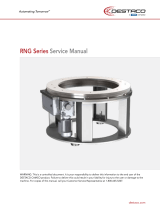
It is also a requirement of the E.U. ATEX directive (Use of Equipment in Potentially
Explosive Atmospheres) that any Bearings should be replaced when they have
reached 90% of their calculated operational life. The following chart is included as a
helpful guide, as the working life of the Cam Follower bearings used in the Pump is
greatly dependant upon the Duty Cycle and Fluid Pressure Output Requirement.
Before any maintenance always switch off the pump and secure against any
unintentional start up.
CAM FOLLOWER REPLACEMENT CHART
0
10
20
30
40
50
60
70
80
90
1
2
3
4 5
6
7 8 9 10 11 12 13 14 15 16 17 18
WORKING PRESSURE (BAR)
MOTOR Hz SETTING
18
MONTHS
24
MONTHS
12
MONTHS
/