Page is loading ...

EN
Service Manual
• 104019 (Japan Model)
• 104018 (USA Model)
• 104017 (EU Model)
IMPORTANT! DO NOT DESTROY
It is the Customer's responsibility to have all operators and service personnel read and understand this
manual.
Contact your local Carlisle Fluid Technologies representative for additional copies of this manual.
READ ALL INSTRUCTIONS BEFORE OPERATING THIS PRODUCT
E2-15 Electric Drive Pump
77-3226 R5.1 www.carlisleft.com

EN
This Declaration of conformity / incorporation is issued under the sole responsibility of the
manufacturer:
Machinery Directive 2006/42/EC
ATEX Directive 2014/34/EU
EMC Directive 2014/30/EU
by complying with the following statutory documents and harmonized standards:
EN ISO 12100:2010 Safety of Machinery - General Principles for Design
EN 12621:+A1:2010 Machinery for the supply and circulation of coating materials under pressure - Safety
requirements
EN 1127-1:2011 Explosive atmospheres - Explosion prevention - Basic concepts
EN 13463-1:2009 Non electrical equipment for use in potentially explosive atmospheres - Basic methods and
requirements
EN 13463-5:2011 Non electrical equipment for use in potentially explosive atmospheres - Protection by
constructional safety "c"
EN 13463-8:2003 Non-electrical equipment for potentially explosive atmospheres. Protection by liquid immersion
'k'
EN 60079-0:+A11:2013 Explosive atmospheres - Equipment. General requirements
EN 60079-1:2014 Explosive atmospheres - Equipment protection by flameproof enclosures "d"
EN 60079-7:2015 Explosive atmospheres. Equipment protection by increased safety "e"
EN 60034-1: 2010 Rotating electrical machines
Providing all conditions of safe use / installation stated within the product manuals have been complied with and
also installed in accordance with any applicable local codes of practice.
29/6/18
Bournemouth,BH11 9LH,UK
II 2 G X IIB T4 (Pump)
II 2 G Exd/Exde IIB T4 IP55 (Motor) CE0722
II 2 GD ck T4 (Gearbox)
EU Declaration of Conformity
Product Description / Object of Declaration:
Electric Pump E2, E4, EV2
Notified body details and role:
Element Materials Technology (0891)
Lodging of Technical file
This Product is designed for use with:
Solvent and Water based materials
Suitable for use in hazardous area:
Zone 1
Protection Level:
This Declaration of conformity / incorporation
is issued under the sole responsibility of the
manufacturer:
Carlisle Fluid Technologies UK Ltd,
Ringwood Road,
Bournemouth, BH11 9LH. UK
Signed for and on behalf of Carlisle Fluid
Technologies UK Ltd:
D Smith
Director of Sales (EMEA)
77-3226 R5.1 2/40 www.carlisleft.com

EN
OPERATOR TRAINING. All personnel
must be trained before operating
finishing equipment.
EQUIPMENT MISUSE HAZARD. Equipment misuse can cause the
equipment to rupture, malfunction or start unexpectedly and result in
serious injury.
PACEMAKER WARNING. You are in the
presence of magnetic fields which may
interfere with the operation of certain
pacemakers.
HIGH PRESSURE CONSIDERATION. High pressure can cause serious
injury. Relieve all pressure before servicing. Spray from the gun,
hose leaks or ruptured components can inject fluid into your body
and cause extremely serious injury.
KEEP EQUIPMENT GUARDS IN PLACE.
Do not operate the equipment if the
safety devices have been removed.
STATIC CHARGE. Fluid may develop a static charge that must be
dissipated through proper grounding of the equipment, objects to be
sprayed and alll other electrically conductive objects in the dispensing
area. Improper grounding or sparks can cause a hazardous condition
and result in fire, explosion or elecrtic shock and other serious injury.
NEVER MODIFY THE EQUIPMENT. Do
not modify the equipment unless the
manufacturer provides written
approval.
KNOW WHERE AND HOW TO SHUT
OFF THE EQUIPMENT IN CASE OF AN
EMERGENCY.
NOISE LEVELS. The A-weighted sound level of pumping and spray
equipment may exceed 85 dB(A) depending on equipment settings.
Actual noise levels are available on request. It is recommended that
ear protection is worn at all times while equipment is in use.
PRESSURE RELIEF PROCEDURE.
Always follow the pressure relief
procedure in the equipment instruction
manual.
WARNING
CAUTION
NOTE
Hazards or unsafe practices which could result in
severe personal injury, death or substantial property
damage.
In this part sheet, the words WARNING, CAUTION and NOTE are used to emphasize important safety information as
follows:
Hazards or unsafe practices which could result in
minor personal injury, product or property
damage
Important installation, operation or maintenance
information.
WARNING
IT IS THE RESPONSIBILITY OF THE EMPLOYER TO PROVIDE THIS INFORMATION TO THE
OPERATOR OF THE EQUIPMENT.
WEAR SAFETY GLASSES. Failure to wear safety glasses with side
shields could result in serious eye injury or blindness.
PROJECTILE HAZARD. You may be
injured by venting liquids or gases that
are released under pressure, or flying
debris.
DE-ENERGIZE, DE-PRESSURISE, DISCONNECT AND LOCK OUT ALL
POWER SOURCES DURING MAINTENANCE. Failure to de-energize,
disconnect and lock out all power supplies before performing
equipment maintenance could cause serious injury or death.
INSPECT THE EQUIPMENT DAILY. Inspect the equipment for worn or
broken parts on a daily basis. Do not operate the equipment if you
are uncertain about its condition.
Read the following warnings before using this equipment.
AUTOMATIC EQUIPMENT. Automatic
equipment may start suddenly without
warning.
PROP 65 WARNING. WARNING: This product contains chemicals
known to the state of California to cause cancer and birth defects or
other reproductive harm.
PINCH POINT HAZARD. Moving parts
can crush and cut. Pinch points are
any areas where ther are moving
parts.
READ THE MANUAL. Before operating finishing equipment, read and
understand all safety, operation and maintenance information
provided in the operation manual.
77-3226 R5.1 3/40 www.carlisleft.com

Fluid Output @ 80 HZ [40 cycles/min]
15 l/m [4.0 US gal/m]
0.75 kW 4Pole 1400 RPM - Japan Model
AC Induction Electric Motor- EU Model
400V 3PH 0.75 kW @ 50HZ
80 kg [176 lbs]
NOTE
Rated 20 to 80 Hz (c/w thermisters)
Max. Inlet Pressure
Total Weight of Pump (inc electric motor)
AC Induction Electric Motor - USA Model
Rated 20 to 80 Hz (c/w thermisters)
50mm [1.97 ins]
Maximum fluid pressure:
20 bar [290psi]
Nominal pump stroke:
Gearbox Oil (USA Model)
Nominal flow volume / cycle:
0.375 l/m [0.10 US gal/m]
Fluid Output @ 20 HZ [10 cycles/min]
3.75 l/m [1.0 US gal/m]
Gearbox Ratio:
56:1
Gearbox Oil (EU Model)
Synthetic 220 (typically Agip Blasia S)
0.75 kW 4Pole 1400 RPM
EEx d 11B T3
460V 3PH 1 Hp @ 60HZ
Class 1, Group D.
EN
SPECIFICATION
2 bar [29 psi]
Fluid outlet connection: 'B'
Fluid inlet connection: 'A'
1'' Sanitary
1'' Sanitary
SHC 630 Synthetic Oil
Pressure when used in 'Smart Mode' (Closed Loop Pressure Mode)
Reduce Maximum working pressure by 2 bar [29 psi] when using in Open Loop Flow Mode
e.g. E2-15 Maximum Set Pressure of 18 bar to operate Pump on a 24/7 basis
77-3226 R5.1 4/40 www.carlisleft.com

EN
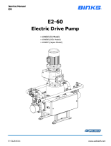
DIMENSIONS AND MOUNTING DETAILS
M6 HEX.
Head screw for pump earth grounding;
the Pump Frame must be wired to a suitable earth
ground to ensure that there is no possibility of static
build up.
77-3226 R5.1 5/40 www.carlisleft.com

EN
INSTALLATION
The Pump Units are designed for location in Zone 1 Hazardous areas, ATEX Category 2.
Electrical connections must be in accordance with Local Regulations for installation in Hazardous Areas.
It is recommended that a Local Control Box is positioned in close proximity to the pump, as a convenient local
Start / Stop facility and Junction box.
The main Pump Control Panel must be positioned within an Electrically Safe Area.
A Pressure switch (and/or Pressure relief valve) must be connected to the outlet manifold port and set to stop the
pump (or relieve the fluid pressure) in the event of the system overpressure
e.g. blocked paint filter, otherwise Pump warranty may be invalidated.
This is necessary to protect the Pump mechanics from overload.
An adapter to mount a pressure switch and pressure sensor is available, see accessories.
It is recommended that the switch setting is set to 1 bar [14.5 psi] above the maximum required pressure.
The maximum pressure setting the Pressure Switch should be set to is 20 bar [305 psi] and 17 bar [246 psi]
respectively.
The Pressure Switch is classified as simple apparatus and as such should be electrically connected as part of an
intrinsically safe electrical circuit.
The Pressure Switch should be wired as a Normally Closed contact (fail safe) and be hard wired to stop the motor
on operation, to minimise response time.
77-3226 R5.1 6/40 www.carlisleft.com

EN
Rated Motor Power
0.75 kW
Rated Motor Current
2 A
Rated Motor Power Factor
Required Inverter Settings
INSTALLATION
Electric Motor
Inverter
0.81
Rated Motor Efficiency
78 %
Rated Motor Frequency
50 Hz
Rated Motor Voltage
Value
Maximum Hz Output
80 Hz
Mininmum Hz Output
20 Hz
Acceleration Ramp
Deceleration Ramp
400 V
Rated Motor Speed
1440 RPM
The motor must be wired to provide a clockwise direction of the cam.
Electric Motors for hazardous areas are specially designed to comply with official regulations concerning the risk
of explosion.
If improperly used, badly connected, or altered no matter how minor, their reliability could be in doubt.
Standards relating to the connection and use of electrical apparatus in hazardous areas must be taken into
consideration.
Only trained personnel familiar with these standards should handle this type of apparatus.
The motor is fitted with PTC temperature sensors (Thermistors).
Once operating temperature is reached, this device quickly changes the resistance;
it must be connected to a suitable releasing device mounted within the control panel and wired to stop the motor
if an over temperature occurs.
5 Seconds
0.1 Seconds
77-3226 R5.1 7/40 www.carlisleft.com

EN
INSTALLATION
• Attach suitable flexible hoses to the inlet and outlet connections.
e.g.,
Suction - Ø28 I.D. [-1 to 10 bar working pressure]
Outlet - Ø25 I.D. [20 bar working pressure]
• Ensure adequate air space around the Pump for maintenance and electric motor cooling requirements.
• Check that the oil plug on top of Gearbox has been replaced with the correct venting plug.
The vent plug is supplied in a bag attached to the gearbox.
• Ensure the gearbox is filled with oil.
77-3226 R5.1 8/40 www.carlisleft.com

EN
Before starting:-
SYSTEM OPERATION
Smart Mode:
• Ensure all electrical and mechanical connections are correctly made.
• All required interlocks are tested and operational.
• Suitable material for pumping is available at the suction hose.
• The outlet connection is not blocked or isolated by any valves.
• Check the gearbox oil level, please note the the gearbox is supplied with life lubricant and does not
need any maintenance.
Set the pump speed to the minimum frequency 20 Hz and start the pump to remove any air from the
circuit.
Inspect for any system leaks.
Set the pump cycle rate to achieve the required paint volume and then adjust the system back
pressure regulator to achieve the desired system fluid pressure.
The return line ‘back pressure’ regulator responds to the changes in system fluid flow demand, (due to
variable paint usage) by dynamically adjusting the paint flow rate returning to the system paint tank,
thus maintaining the set pressure.
77-3226 R5.1 9/40 www.carlisleft.com

EN
COVER C/W CAP
FIXINGS
1
ATEX GEARBOX
(Not Shown)
194944
2
4
Ø10 SPRING WASHER (ST ST)
165134
7
2
E2-15 MANIFOLD & PRV ASSEMBLY
194248
10
0.75KW ATEX MOTOR
& GEARBOX
0.75KW ELECTRIC MOTOR
(Not Shown)
1 HP ELECTRIC BALDOR MOTOR
(Not Shown)
MARATHON MOTOR
(Not Shown)
USA MODEL
1
3
194919
ITEM
REMARKS
193118
3
11
194558
FLUID SECTION
193092
QTY
1
JAPAN MODEL
4
163144
4
2
1
165947
193708
1
8
COVER C/W CAP
FIXINGS
JAPAN MODEL
165108
2
193090
1
JAPAN MODEL
DESCRIPTION
GEARBOX
(Not Shown)
3
193093
3
1
1
PART NUMBER
8
165123
6
5
4
8
9
194900
1
E2-15 MECHANICAL ASSY
M8 HEXAGON NUT
Ø10 HEXAGON NUT
E2-15 CAP HEAD SCREW
M10 x 35 WASHER
PARTS LIST - Pump Assembly
M8 HEXAGON NUT
77-3226 R5.1 10/40 www.carlisleft.com

EN
KEY
(Reverse for assembly)
LOCTITE
TORQUE
MAINTENANCE ORDER
GREASE INTERNAL
(AGMD-010)
GREASE
77-3226 R5.1 11/40 www.carlisleft.com

EN
PART NUMBER
DESCRIPTION
194589
2
INLET MANIFOLD
194279
5
1
1
OUTLET MANIFOLD
194280
6
ITEM
10
QTY
REMARKS
192009
7
2
1
104167
1
3
192206
10
1
8
194590
194109
4
1
PARTS LIST - PRV and Manifold Assembly
1'' PRESSURE RELIEF VALVE
1 & 1 1/2 SANITARY CLAMP
1'' SANITARY ELBOW
1'' SANITARY GASKET - PTFE
1'' EXT. SANITARY ELBOW [96.5mm]
1'' EXT. SANITARY ELBOW [82mm]
77-3226 R5.1 12/40 www.carlisleft.com

EN
KEY
(Reverse for assembly)
LOCTITE
TORQUE
MAINTENANCE ORDER
GREASE INTERNAL
(AGMD-010)
GREASE
77-3226 R5.1 13/40 www.carlisleft.com

EN
192650
20
22
192849
CARRIAGE ASSEMBLY
2
SPRING RETAINING WASHER
10
4
177020
16
19
192441
2
5
164471
4
6
165044
4
165108
8
8
7
165100
2
3
165351
4
4
165666
13
4
165134
165123
163161
REMARKS
4
2
1
160524
CARRIAGE SPRING
4
2
4
PART NUMBER
DESCRIPTION
QTY
12
4
14
165958
6
4
11
163144
192400
18
4
163921
4
165661
177021
17
GREASE NIPPLE
2
15
165959
2
4
2
SHAFT CLAMP ASSY
192668
21
M16 EYE BOLT
M8 MUD GUARD WASHER - STST
M6 WASHER (BRASS)
M8 NYLOC NUT
M8 HEXAGON NUT
M8 PLAIN WASHER A2 ST ST
M10 SPRING WASHER (ST ST)
M8 SPRING WASHER (ST ST)
M16 SPRING WASHER
M12 SPRING WASHER (ST ST)
M6 x 25 CAP HEAD SCREW (ST ST)
M10 x 21 CAP HEAD SCREW
M12 x 50 HEX HEAD BOLT (PLATED)
M8 x 20 GRUBSCREW - STST
M8 x 45 GRUB SCREW
M6 x 20 HEX HEAD CAP SCREW
(BRASS)
M8 x 20 BUTTON HEAD CAP SCREW
PARTS LIST - Mechanical Assembly
9
ITEM
77-3226 R5.1 14/40 www.carlisleft.com

EN
8 x 7 x 30 KEY
Ø30 COUPLING SPACER
Ø6 GREASE HOSE
31
LINEAR SPRING PIN
2
192869
25
GREASE BULKHEAD
192870
2
29
192878
1
32
192879
30
2
192880
BELL HOUSING CAM ASSY
1
MAIN BODY MACHINING
ITEM
PART NUMBER
DESCRIPTION
QTY
REMARKS
❸
26
2
193131
33
192872
194198
35
1
192854
23
LEAK DETECTION HOSE ASSY
194540
SPACER
4
193130
36
ELBOW FITTING
2
Ø10 x 1/4 BSPT EXT PUSHIN
1
LINEAR BEARING ROD
27
34
193695
1
24
192860
MOUNTING FRAME
2
2
DRIVE SHAFT COUPLING
1
192875
28
PARTS LIST - Mechanical Assembly
77-3226 R5.1 15/40 www.carlisleft.com

EN
KEY
(Reverse for assembly)
LOCTITE
TORQUE
MAINTENANCE ORDER
GREASE INTERNAL
(AGMD-010)
GREASE
77-3226 R5.1 16/40 www.carlisleft.com

EN
Part No. 12 Remove inner race & grease 502375
Part No. 6 To be tightened using tool 193119
Part No. 4 To be tightened using tool 193120
Part No. 1 Grease using 502375
Part No. 11 To be pressed into housing using tool 193121
NOTE:
KEY
(Reverse for assembly)
LOCTITE
TORQUE
MAINTENANCE ORDER
GREASE INTERNAL
(AGMD-010)
GREASE
77-3226 R5.1 17/40 www.carlisleft.com

EN
Ø30 x Ø42 x 7 SEAL
M5 x 25 CAP HEAD SCREW
M5 x 16 CAP HEAD SCREW (ST ST)
M25 BEARING LOCKNUT
1/8'' BSPT x 45° GREASE NIPPLE
M30 BEARING LOCKNUT
M8 x 50 CAP HEAD SCREW
Ø25 x Ø52 ROLLER BEARING
Ø30 x Ø72 x 30.2 BALL BEARING
192859
10
13
4
1
192703
6
TOP BEARING CAP
8
BOTTOM SHAFT
9
165558
14
1
165974
192858
194513
1
1
162709
1
ITEM
PART NUMBER
DESCRIPTION
QTY
REMARKS
❸
6
163960
2
6
165972
3
BELL HOUSING MACHINING
1
192853
7
1
192857
8
BOTTOM BEARING CAP
1
BOTTOM BEARING HOUSING
1
❸
192873
11
1
❸
192874
12
SHAFT ASSEMBLY
CONSTANT VELOCITY CAM
192850
15
16
192855
1
17
192856
1
TOP SHAFT
1
1
5
192650
1
PARTS LIST - Bell Housing & Shaft Assemblies
77-3226 R5.1 18/40 www.carlisleft.com

EN
Bell Housing & Shaft Assemblies
77-3226 R5.1 19/40 www.carlisleft.com

EN
PARTS LIST - Carriage Assembly
10 x 12 x 14mm LINEAR BEARING
Ø25 LINEAR BEARING
1/8 R - 6mm PUSH IN ELBOW
Ø47 CAM FOLLOWER
Ø46 CIRCLIP
M6 x 12 CAP HEAD SCREW
M12 PREVAILING TORQUE NUT
Ø41 x 1.78 SECTION O-RING
2
193112
13
11
192863
FOLLOWER NUT WASHER
1
1
1
192851
1
2
3
4
192871
4
REMARKS
7
CARRIAGE ADAPTOR
166156
4
12
162734
1
163159
2
165542
LINEAR BEARING HOUSING
2
12
9
192861
1
10
192862
ITEM
PART NUMBER
DESCRIPTION
QTY
CAM FOLLOWER PIN
LINEAR BEARING CARRIAGE
1
192852
8
5
192392
1
6
192661
77-3226 R5.1 20/40 www.carlisleft.com
/