Page is loading ...

KA42E Issue 17 © 2017 Page 1 of 8
INSTRUCTION MANUAL
Introduction
Assembly Procedure
Maintenance Procedures
K4/KR SUPERLUBE™
CAUTION
Important Information
PLEASE READ THIS SAFETY
INFORMATION CAREFULLY BEFORE USE.
Read and retain this instruction manual to assist you
in the operation and maintenance of this product.
‘CAUTIONS’ are listed throughout this manual to
advise of actions which may cause damage to your
equipment.
NOTE: Your Super-Lube is designed for use with
greases up to NLGI No2.
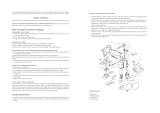
Operating Procedure
The Macnaught K4/KR Super-Lube is a
portable high pressure manual greasing system,
supplied with spring loaded pump, lid, rubber
edged follower plate, 3 metres of special
Macnaught grease hose and a KR Pressurite
(High pressure / High Volume) grease gun.
1) Insert follower into the grease pail with the
follower boss facing upwards. Push down firmly
until grease emerges through the boss.
2) Assemble the bung adaptor to the lid using the
socket head bolts and nyloc nuts.
3) Push the pump tube through the bung adaptor
and follower boss then sit the lid on the rim of the
container. Hand tighten the 3 thumb screws evenly
under container rim.
4) To prime, push the handle down several times to
start grease flowing through the grease hose. When
the hose is full of grease, the handle will stay down.
5) Squeeze and hold the gun handle to bleed air out
of the system. When fully bled, container grease
will emerge from the gun coupler.
Note: It may be necessary to repeat step 4.
If the unit fails to prime, bump the container base
several times on a solid surface in order for air
bubbles to leave the grease.
When greasing, the handle will rise slowly. When
the handle is fully up and the gun loses pressure,
push the handle down once or twice to re-prime the
pump and continue greasing.
Each pump prime will provide sufficient grease for
up to 60 shots of grease.
The KR Pressurite gun is normally operated on HI-
VOLUME. Should high pressure be required push
the switch on the gun to HI-PRESSURE.
Note: Once bled of air, the Super-Lube does not
usually require bleeding. To settle the grease and
remove air bubbles bump container base several
times on a solid surface.
Springs inside tubes (4 & 7) are compressed.
When removing the tubes to service seals or
replace the springs, remove the handle (1) and
hold tube (7) firmly against the spring pressure
while removing the nut (3). Gently release the
spring pressure against the tube (7).
Includes models
K4-01
K4-02
K4-07

KA42E Issue 17 © 2017 Page 2 of 8
Product Features
Removing a KY Coupler from a Grease Nipple
Operation on the
High Volume Setting
Operation on the
High Pressure Setting
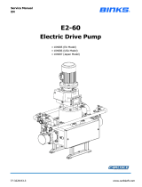
K4 Pump Unit Parts Diagram
15
2
1
4
3
19
18
17
16
13
5
14
6
20
21
22
23
7
8
24
25
26
9
10
11
27
12
28
29
30

KA42E Issue 17 © 2017 Page 3 of 8
K4 Pump Parts Listing
ITEM No. off Order for replacement KIT. REF Description
K4-1K (A) Overhaul kit
1 1 Handle
2 1 Shakeproof Washer
3 1 KA90s 3/8" NUT
4 1 Upper Spring Cover
5 1 Outer Spring
6 1 Inner Spring
7 1 Low er Spring Cover
8 1 A Washer
9 1 A Back up Washer
10 1 A O'ring (BS111)
11 1 N/A - New pump required Pump Body
12 1 N/A Hose Tail 5/8" x 3/8" BSP
13 1 Upper Piston Rod
14 1 Low er Piston Rod
15 1 A Roll Pin
16 1 Piston
17 1 A O'ring (BS212)
18 1 A Ball - 3/4"
19 1 A Screw
20 1 n/a Suction Tube
21 1 A Ball - 3/4"
22 1 AG54s A Pin
23 1 A Footvalve
24 1 * Refer model specific part Follow er Assembly
25 1 A O'Ring (BS218) - Follow er
26 1 * refer model specific part Lid assembly
27 3 A Thumb Screw Set
28 1 J27s Lid adaptor set (incl screw /nut set)
29 1 KR KR Gun
30 1 KH45s Hose Assembly
Lid Assemblies *
PK85GENs - K4-01 / K4-04
PK92s - K4-02
PK98s - K4-07
Follow er Assem blies *
J11s - K4-01 / K4-04
J77s - K4-02
J78s - K4-07

KA42E Issue 17 © 2017 Page 4 of 8
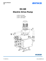
KR Pressurite Gun Parts List
KR Pressurite Gun Parts Diagram
Order for replacement
Item No. off New part/set KIT. REF DESCRIPTION
KR-1K (Kit A) (A) OVERHAUL KIT
KR-2K (Kit B) (B) PISTON KIT
1 1 N/A - new gun required Gun Body
2 1 A & B Piston spring
3 1 A & B Valve Stem (Piston)
4 1 A & B Spring, Piston Check
5 1 A & B 7/32" Ball. Piston
6 1 A & B Glyde Ring
7 1 A & B Glyd Ring O'ring (BS111)
8 1 A & B Piston
9 1 A Valve Seat
10 1 Operating Plunger Control
11 2 Cap Socket 1/2"X3/16" w hit
12 1 KR12s A Spring, (inlet check)
13 1 A 5/16" Ball Inlet
14 2 A O' ring, Seal Body (BS013)
15 1 A O' ring. Plunger Control (BS008)
16 1 Control Body Assy
17 1 A Washer, Hose Adaptor
18 1 A O' ring, Hose Adaptor (BS113)
19 1 Ball End, Hose Adaptor
20 1 Ball. Socket Retainer
21 1 A Keeper Screw (outlet)
22 1 A Spring (Outlet)
23 1 A 1/4" Ball (outlet)
24 1 Outlet Body
25 2 A Teflon Back Up Washer
26 1 A O'ring. Piston (BS012)
27 1 KY Coupler
28 1 KH23s Extension Tube
29 1 N/A - new gun required Handle
30 1 A & B Handle pin
31 2 A & B Drive Screw
32 1 A Retainer O'ring (BS017)

KA42E Issue 17 © 2017 Page 5 of 8
Troubleshooting Guide—K4 Pump Unit
Troubleshooting Guide—KR Pressurite Gun
Problem Cause Remedy
The handle rises slowly
when not in use.
Dirt trapped between inlet ball (18)
and piston (16).
a) Unscrew the Pump Body (11) from the Suction Tube (20) and withdraw the
assembly. Clean the ball (18) and piston (16) then reassemble.
The piston O-Ring (17) is worn. Replace the piston O-Ring (17).
The handle springs up and the
unit will not pump grease.
Air lock:
1) Dent in the container.
2) Damaged follower O-Ring.
1) Remove dent or tilt the follower under the dent.
2) Replace the O-Ring in the follower.
Grease container empty. Change container or refill the old container.
The foot valve assembly (21, 23 & 22)
is faulty.
Unscrew the old foot-valve assembly (21, 23 & 22) and replace.
The handle stays down, but
the unit will not pump grease.
The grade of grease is too heavy Use up to NLGI No 2 grease.
Grease leaks out from
between the lower spring
cover (7) and the pump body
(11)
Pump Body O-Ring (10) is Damaged. Use a 15mm spanner to hold the nut (3) underneath the pump handle (1) and
untighten the pump handle (1). Remove the shake-proof washer (2) and hold down
the upper spring cover (4) against the spring tension and undo the nut (3). Slowly and
carefully release the spring tension of the upper spring cover (4). Once complete,
remove the one or two springs (5 & 6) and the lower spring cover (7). Remove the
steel washer (8) and replace the back-up washer (9) and O-Ring (10).
Reassemble the pump in the same way as above but in the reverse order.
Grease leaks from the bottom
of the pump body (11)
Thread sealant damaged
Unscrew the suction tube (20) from the pump body (11), clean the threads of both the
pump body and suction tube, apply thread sealant to the suction tube and re-assemble
the pump.
Problem Cause Remedy
Coupler leaks. a) Dirt under the outlet ball (23) seat
Note: There is nothing wrong with the coupler itself.
a) Remove the extension tube (28), spring keeper
screw (21), spring (22) and ball (23).Clean the seat
and replace the ball, spring and spring keeper screw
(part way). Prime the pump and screw in the spring
keeper screw until the grease stops leaking. Then
screw in an extra 2 full turns. Reassemble extension
tube (28).
Note: If the coupler still leaks, replace the complete
outlet body assembly. When refitting the outlet body
(24) hold the handle (29) in the closed position.
Enable the back-up washer and o’ring to enter
squarely onto the piston.
b) The valve stem (3) is holding the outlet ball (23) off its
seat.
b) Replace the piston assembly.
Gun leaks at the back end of the piston. Glyd ring worn Replace the piston assembly.
Gun fails to deliver grease on the
high pressure setting.
a) Faulty piston. a) Replace the piston assembly.
b) Seals (25, 26) are worn. b) Replace seals (25, 26) in the outlet body.
c) Valve stem (3) has become loose from the piston (8). c) Replace piston assembly.
Gun fails to deliver grease on the
high volume setting.
a) Dirt on the inlet valve seat (9) a) Remove control body (16), tap out the valve seat
(9), o’ring (14), ball (13) and spring (12). Clean parts
and replace in the correct order.
b) Operating plunger control (10) sticking in body (16). b) Replace the control body assembly.
Push rod in the control body leaks O’ring (15) damaged. Remove the control body and replace worn or
damaged parts.
The gun leaks at the swivel joint. Worn seals (18, 32) Replace swivel seals.
When on the high volume the gun
is too slow or hard to operate.
a) Springs (2 or 4) may have collapsed. a) Fit KR-1K overhaul kit.
b) Grade of grease is too heavy. b) Change to NLGI No 2 grease or lighter.
c) Too much compression on the outlet spring (22). c) Reset the spring tension (Refer to A , a) in trouble
shooting guide) or replace the outlet body assembly.

KA42E Issue 17 © 2017 Page 6 of 8
Notes

KA42E Issue 17 © 2017 Page 7 of 8
Notes

KA42E Issue 17 © 2017 Page 8 of 8
Note:
This product should be disposed of according to all applicable local
and national government environment regulations and guidelines.
For Warranty Terms and Conditions see macnaught.com.au
For a list of Australian Service Centres see macnaught.com.au
/