Page is loading ...

destaco.com
Automating Tomorrow™
WARNING: This is a controlled document. It is your responsibility to deliver this information to the end user of the
DESTACO CAMCO product. Failure to deliver this could result in your liability for injury to the user or damage to the
machine. For copies of this manual, call your Customer Service Representative at 1-800-645-5207.
RNG Series Service Manual

RNG Series
Service Manual

3
Table of Contents
Introduction .......................................................................................................................... 4
Warnings and Cautions ...................................................................................................................................4
Spare Parts Kit .................................................................................................................................................4
Before Starting .................................................................................................................................................4
Required Tools.................................................................................................................................................5
IMPORTANT ....................................................................................................................................................5
Torque Requirements for Tightening Screws ..................................................................................................5
Inspection ............................................................................................................................. 6
Prepare for Inspection .....................................................................................................................................6
Inspection .........................................................................................................................................................6
Oil Seal Replacement ........................................................................................................... 7
Oil Seal Removal .............................................................................................................................................7
Oil Seal Installation ..........................................................................................................................................7
Cam Follower Replacement ................................................................................................. 9
Cam Follower Removal ...................................................................................................................................9
Cam Follower Installation ............................................................................................................................. 10
Cam and/or Input Shaft Replacement ................................................................................ 11
Input Shaft Removal ..................................................................................................................................... 11
Cam Installation ............................................................................................................................................ 12
Input Shaft Installation .................................................................................................................................. 12
Setting Cam .................................................................................................................................................. 14
Follower Wheel/Output Bearing Replacement ................................................................... 16
Follower Wheel/Output Bearing Removal .................................................................................................... 16
Follower Wheel/Output Bearing Installation ................................................................................................. 16
Final Assembly ................................................................................................................... 17
How to Order Parts............................................................................................................. 18
Required Information .................................................................................................................................... 18
To Order Parts .............................................................................................................................................. 18
Under Warranty............................................................................................................................................. 18
Out of Warranty............................................................................................................................................. 18
750RNG Parts Drawing ...................................................................................................... 19
750RNG Parts List ............................................................................................................. 20
1100RNG & 1550RNG Parts Drawing................................................................................ 21
1100RNG Parts List ........................................................................................................... 22
1550RNG Parts List ........................................................................................................... 23
Felt Seal Installation ........................................................................................................... 24
1
RNG Series
Service Manual

4
Introduction
This service manual pertains to the disassembly and assembly of the CAMCO Ring Index Drive
models 750RNG, 1100RNG and 1550RNG.
This manual is to be used in conjunction with the General Service Manual, which describes the
lubrication and general maintenance of CAMCO Index Drives.
A cross section view of a typical CAMCO Ring Index Drive is included in this manual. Item numbers
within this Service Manual refer to the cross section view. Also included is a generic Bill of Materials
for your convenience in identifying and ordering spare or replacement parts. Always provide the
serial number from the Index Drive when ordering spare or replacement parts.
Some users of Index Drives have facilities and trained personnel to accomplish service repair. You
must determine the extent to which intricate servicing should be done by your own maintenance
personnel. When in doubt, DE-STA-CO recommends the assistance of a trained DE-STA-
Cserviceman when making repairs.
Warnings and Cautions
Statements in this manual preceded by the words WARNING or CAUTION and printed in italics are
very important. CAMCO recommends you take special notice of these during service or repair.
WARNING
Means there is the possibility of personal injury to yourself or others.
CAUTION
Means there is the possibility of damage to the CAMCO unit.
Spare Parts Kit
DE-STA-CO offers spare parts kits for all CAMCO index drive models manufactured by DE-STA-
CO. The spare parts kit for the CAMCO Ring Index Drive includes input oil seals, input bearings,
and input shims. Cam followers are not included in the spare parts kit. CAMCO recommends a
spare parts kit and the appropriate number of cam followers be purchased and kept on hand prior to
any disassembly of your CAMCO Ring Index Drive.
Before Starting
DE-STA-CO uses either Red Perma-Lok®‚ #HM118 or Green Perma-Lok®‚ #HM160 to secure most
screws and set screws. Exceptions are removable covers, etc. If you encounter a fastener that is
difficult to remove, apply heat to the screw and remove while still warm.
CAUTION
Localized heat can distort the part. Do not overheat any item.
WARNING
Disassembly and repair of a CAMCO Ring Index Drive requires lifting and manipulating large
cumbersome parts.
CAUTION
Disassembly and repair of a CAMCO Ring Index Drive requires special tools not normally available.
A partial list of commercially available tools is provided. Some special tools and equipment must be
manufactured by maintenance personnel on site. Using the proper tool is mandatory for
successfully completing repairs.
2
RNG Series
Service Manual

5
Required Tools
Repair of any CAMCO Ring Index Drive requires the following tools:
1. Spanner Wrench #10
2. Socket for M8 FHCS
NOTE
During some portions of repair, the motor drive package can be used to rotate the input shaft and
follower wheel. Some means for running the motor at extremely low speeds is mandatory. Use
extreme caution when operating the motor during repairs. Alternatively, loosen the shrink disk
connection between the reducer and Ring Drive input shaft and hand crank the input from the shaft
opposite the reducer. The input shaft has a tapped hole on the end and may be cranked by
inserting a screw and using a wrench to turn the shaft.
IMPORTANT
Before starting disassembly of your CAMCO unit you should read and review all instructions. These
provide important information on parts and procedures necessary to successfully complete your
repair.
Comply with all WARNINGS and CAUTIONS!
Read the "Trouble Shooting Guide" section in your General Service Manual before disassembling
CAMCO units. DE-STA-CO recommends the assistance of a trained DE-STA-CO serviceman
whenever repairs are more involved than replacing oil seals or cam followers.
Torque Requirements for Tightening Screws
This table provides torque specification for Metric Socket Head Cap Screws.
Metric Socket Head Cap Screw
Thread Size
Torque
ft-lb
Nm
M5
6
9
M6
12
16
M8
29
39
M10
57
77
M12
100
136
Torque values are for non-lubricated threads, coated only with a residual film of oil, as received
from the manufacturer. Values are for threads engaged 1.5 times the screw thread diameter and
installed into steel parts.
3
RNG Series
Service Manual

6
Inspection
Prepare for Inspection
1. Remove only those structural members
and fixtures required to gain access to the
index drive and to allow for completing the
necessary procedures.
2. Drain oil and flush with flushing solvent.
Retain any chips or broken pieces you
may find. These may aid in diagnosis.
2.1. Oil may be drained by removing
the Magnetic Drain Plug (Item #25).
3. Remove the socket head cap screws
(Item #33) and cover (Item #5).
Inspection
1. While slowly rotating input, inspect cam
(Item #1) surface to determine if cam must
be replaced. Inspect for a rough or rippled
surface, gouge marks, pitting and other
imperfections.
2. Slowly index the unit and place the Index
Drive in a dwell position.
2.1. Check for preload by trying to rotate
the cam followers (Item #15) that are
in dwell.
2.2. Visually observe the surface of the
outer shell of the cam follower.
Inspect followers for damage or radial
looseness. Looseness should not
exceed .001 inch. Do not confuse
radial looseness with axial endplay.
End play will be from .03 to .06 inch
as a normal condition. If endplay
exceeds .06 inch the followers should
be replaced.
NOTE: Generally, cam followers are replaced
as added insurance against later failure.
When in doubt, replace the cam followers.
3. Broken cam followers indicate possible
damage to the follower wheel. Remove
any broken cam followers. See the section
titled "Cam Follower Replacement", in this
Service Manual. Inspect the cam follower
stud hole in the follower wheel for
damage, and to determine whether the
cam follower stud hole is "wallowed out",
elongated, oval, etc. Using the nominal
size of the cam follower stud as a guide,
verify a press fit between the stud and the
hole, -. 0005 to -. 0010 inch for the full
length of the hole.
4. Grinding noises during each index may
indicate damage to the output bearing
(Item #14 ). Further inspection requires
removal of the indexing ring (Item #2 ).
See the section titled "Follower Wheel /
Output Bearing Replacement" in this
Service Manual.
5. Replace cam followers if loose in dwell or
if the outer shell is visibly damaged. See
the section titled "Cam Follower
Replacement" in this Service Manual.
6. Replace the cam if imperfections are
noted. See the section titled "Cam and/or
Input Shaft Replacement" in this Service
Manual.
7. Replace the follower wheel if follower
holes are oversized. See the section titled
"Follower Wheel / Output Bearing
Replacement" in this Service Manual.
Alternatively, the follower wheel/output
bearing may be returned to DE-STA-CO
for rebuild.
4
RNG Series
Service Manual

7
Oil Seal Replacement
DE-STA-CO recommends replacing the Input
oil seals (Item #11) anytime the input is
disassembled regardless of whether they are
damaged or not. After being in service for
some time, the sealing lip can become brittle
and easily cracked. Most damage to oil seals
occurs at assembly when recommended seal
installation procedures are not followed.
To replace the oil seal on the reducer side of
the index drive, remove the reducer and
additional drive equipment as necessary to
gain access to the seal. See the reducer and
other manufacturers’ Service Manuals for
instructions on removing this equipment. On
the other side of the index drive, remove the
cycle cam and limit switch or other equipment
as necessary to gain access to the oil seal.
Oil Seal Removal
1. To remove the oil seal, use a sharp punch
and punch two (2) diametrically opposed
holes through the case of the seal. Install
sheet metal screws into the holes.
2. Use a Slide Hammer or Pliers (Vise Grips)
to grip the sheet metal screws to pull out
the existing seal.
CAUTION
Do not drill holes in the case of the seal.
Chips will get into the unit and they cannot be
easily removed. A punched hole provides a
better "bite" when installing sheet metal
screws into the metal case.
Oil Seal Installation
1. Check new seal for damage that may
have occurred prior to installation.
1.1. An oil seal with a sealing lip that is
turned back, cut or otherwise
damaged should be replaced and not
used.
1.2. Likewise, if the outer face or outside
diameter is bent or otherwise
damaged, replace the oil seal.
2. Check the input shaft for surface nicks,
burrs or a groove from the sealing lip.
Look for spiral machine marks that can
damage the seal lip.
2.1. An input shaft with a groove from the
sealing lip can be repaired with a
Chicago Rawhide Speedi-Sleeve‚ or
similar product from another
manufacturer. Consult the
manufacturer for installation
instructions.
2.2. Alternatively, the input shaft can be
replaced instead of repaired.
3. Check the end of the input shaft and
remove any burrs or sharp edges. The
end of the shaft should be chamfered.
4. Check splines and keyways for burrs or
sharp edges.
5. Wrap the input shaft with plastic shim
stock as a temporary sleeve to guide and
protect the sealing lip.
6. Check the sealing lip direction. Make sure
the new seal faces the same direction as
the original. DE-STA-CO’s standard
practice is to mount the seal so the lip
faces the lubricant or fluid to be sealed.
7. Pre-lubricate the sealing element by
wiping the surface with the lubricant being
retained. Apply a thin layer of "General
Electric Silicone Rubber RTV-6" or
equivalent to the cartridge bore as a
sealant. When the seal in pressed into
place, a bead of sealant will form at the
back edge of the steel case and prevent
any leakage around the outside edge of
the seal.
8. Whenever possible use an installation tool
that has been specifically manufactured
for installing the seal.
8.1. Installation tools should have an
outside diameter .125 inch (3 mm)
5
RNG Series
Service Manual

8
larger than the bore size. The bore
should be .005” (.127 mm) larger than
the shaft size, and the face of the tool
should be relieved so that pressure is
applied only near the outside
diameter of the seal.
8.2. During installation press the seal
flush to the cartridge face to avoid
cocking the seal in the bore. This also
positions the seal correctly on the
shaft.
9. When an installation tool cannot be
manufactured, install the seal by tapping
uniformly around the seal with a soft
hammer. Avoid cocking the seal and
make sure the face of the seal is square
to the bore.
6
RNG Series
Service Manual

9
Cam Follower Replacement
Cam Follower Removal
Instructions for replacing cam followers
assume the cam and follower wheel will not
be removed. If the follower wheel will be
removed, proceed to the section titled
"Follower Wheel and/or Output Bearing
Replacement" in this Service Manual.
Likewise, if the cam will be removed, proceed
to the section titled "Cam and/or Input Shaft
Replacement" in this Service Manual.
Otherwise, proceed with the following steps.
If the machine builder has provided access to
the cam follower screws, the tooling does not
have to be removed. Otherwise the support
structure and fixtures can be removed as
necessary, or the support structure and
fixtures can be lifted two to three feet above
the unit and supported by appropriate
scaffolding. CAMCO recommends using
professional machinery riggers for this
purpose. The assistance of a CAMCO trained
serviceman is recommended.
Refer to the itemized cross-section drawings
beginning on page 19 for identification of
parts
1. Remove socket head cap screws (Item #
34) and remove Dial Ring (Item #2).
2. Remove lower bore plug (Item #27)
located directly opposite from the cam box
(Item #6).
NOTE: The bore plug may be damaged
during removal. Have a replacement on hand
before beginning any repairs.
2.1. Hit one end to tilt the plug then pry off
with screwdriver. Alternatively, drill a
hole in the center of the plug and pull
out with a screwdriver.
3. Hand crank the Ring Drive input shaft
(Item #18) or use the motor and drive
package to rotate the input shaft and
follower wheel until a follower is
positioned directly above and centered on
the removal opening.
4. Remove , the cam follower screw (Item
#20) and the heavy washer (Item #16).
CAMCO used Red Perma-Lok‚ to secure
these screws If you encounter difficulty
when removing the screw, apply heat to
the screw and remove while still warm.
CAUTION
Localized heat can distort the part. Do not
overheat any item.
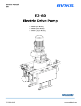
5. Using a large soft faced
hammer and a soft pin,
drive the cam follower
downward and out through
the follower wheel. Take
care not to hit the edges of
the bore. Using a tool as
shown (inserting narrow
pin in tapped hole in
follower stud) will prevent
damaging the cam
follower bore by keeping the pin centered.
Alternatively, you can use a slide hammer
and pull the follower out from the bottom
by using the hole tapped in the bottom of
the cam follower.
6. Inspect the cam follower stud hole for
roundness and size. The cam follower
stud hole must be an interference fit. The
cam follower holes must be -.0005 to
-.0010 inch (.013 - .025 mm) for the full
length of the hole. Check the follower
holes for roundness. These holes should
be round within .0005” TIR (.013 mm) to
permit reuse of the follower wheel. These
holes may be worn-out due to overloads.
CAUTION
Do not use a follower wheel with oversize
follower holes. The cam followers and cam
will fail prematurely. Replace the follower
wheel / output bearing or return to DE-STA-
CO for rework.
0.63″
0.25″
7
RNG Series
Service Manual

10
Cam Follower Installation
The instructions for replacing cam followers
assume the follower wheel and cam were not
removed. Cam followers will be installed one
at a time through the follower access hole in
the housing. If the follower wheel was
removed, proceed by repeating the first four
steps until all cam followers have been
installed in the follower wheel.
If the cam was removed but not the follower
wheel, proceed by repeating the first four
steps until all but two cam followers have
been replaced. Also see additional
instructions below.
NOTE: You will need to purchase or
manufacture a tool to keep the cam
follower square to the bore in the follower
wheel during installation and prevent
damage to both the cam follower and the
wheel.
The tool can be made from round stock.
Bore and face the stock to suit the
follower:
1.375” dia. follower: 1.376” (34.95 mm)
bore
1.500” dia. follower: 1.501” (38.13 mm)
bore
1. Deburr the cam follower stud before
installation.
2. Coat the follower wheel stud hole with
anti-seize lubricant. Place a cam follower
into the follower wheel hole.
3. Push the cam follower upward hard
enough to press the cam follower into the
follower wheel hole using one of the
methods described below. Make sure the
shoulder on the cam follower seats
against the follower wheel.
Insert a screw into the bottom of the
follower and slide the follower into the
tool. While holding the tool against
the face of the wheel, tap the screw
to drive the follower into the bore until
it is seated against the wheel.
Alternatively, you can use the method
from step 3.1 to insert the cam
follower approximately ¼” (6 mm) into
the follower wheel bore then use a
slide hammer from the top to pull the
follower up thru the follower bore until
it is seated against the wheel.
CAUTION
Make sure the shoulder of the cam follower is
seated against the follower wheel and make
sure the follower is installed straight and in
line with the hole. Damage to the cam
follower, follower wheel or cam could occur if
cam follower is improperly aligned during
installation.
4. Install the heavy-duty washer (Item #16)
and flat head cap screw (#20), assembled
as shown in the cross-section drawing in
this Service Manual. Use Red Perma-
Lok®‚ and torque the socket head cap
screw to specification. The tightening
torque depends on the size of the cam
follower. See the table titled "Torque
Requirements for Tightening Screws" in
this Service Manual for tightening torque.
5. Repeat steps to install all cam followers.
6. Install new bore plug (Item #27) using a
round, flat plate larger than plug to press
in plug and seat flush to bearing.
7. Re-install the Dial Ring (Item #2) with the
socket head cap screws (Item #34).
8
RNG Series
Service Manual

11
Cam and/or Input Shaft Replacement
Input Shaft Removal
Instructions for removing the cam and input
shaft assume the follower wheel will not be
removed. If the follower wheel will be
removed, proceed to the section titled
"Follower Wheel and/or Output Bearing
Replacement" in this Service Manual.
Otherwise, proceed with the following steps.
The cam box should be supported during
removal
1. Remove motor/reducer drive package
(Item #19).
2. Remove housing (Item #6) from the base
plate (Item #8).
2.1. Have support for the
housing/cam/input shaft assembly no
more than a few inches from the
bottom of the housing (Item #6).
2.2. Remove the two screws (Item #36)
from the opposite corners adjacent to
the pull dowels (item #32) and
replace with threaded rods and nuts.
Drive the nuts loosely to the base
plate (Item #8)
2.3. Remove the remaining screws (Item
#36).
2.4. Remove pull dowels (Item #32) with
slide hammer
2.5. Slowly lower the housing (Item #6) by
alternately unthreading the nuts until
the housing assembly is free of the
base plate.
2.6. Move housing assembly to bench
and clamp in place.
3. Bend lockwasher (Item #23) tabs over and
away from locknut.
4. Loosen the locknuts (Item #22) that
secure the cam to the input shaft (Item
#18). DE-STA-CO uses Green Perma-
Lok‚ to secure the locknuts. If you
encounter difficulty, apply heat to the
locknut and remove while still warm.
CAUTION
Localized heat can distort the part. Do not
overheat any item.
4.1. Use a Spanner Wrench that has been
locked (jammed) against the side of
the housing to hold the locknut while
turning the input shaft. Use a hand
crank to rotate the input shaft and
break loose the locknuts.
4.2. Break loose the locknuts.
4.3. In some cases it might be necessary
to split the locknut before it will break
loose. Use a cold chisel or other
suitable tool for this purpose.
5. Remove the Input Shaft (Item #18)
5.1. Install an eye bolt into the threaded
"lifting hole" in the cam (Item #1) and
support with an overhead crane.
5.2. Remove all socket head cap screws
(Item #31) securing the two (2)
bearing cartridges (Item #4) to the
housing (Item #6) and remove the
bearing cartridges.
5.2.1. This can be done by striking
the cartridge with a soft faced
hammer and then prying the
cartridge away from the housing.
NOTE: Cartridges have O-Rings (Item
#10). Make sure the O-Rings and the
housing bores are not damaged.
5.2.2. The input oil seal (Item #11)
and input bearing cup (Item #12)
will stay with each bearing
cartridge when it is removed.
5.2.3. Make sure to note the color
and number of any input shims
(Item #3) at each cartridge. The
9
RNG Series
Service Manual

12
color and number of shims used
determines bearing preload.
5.3. Remove the input bearing cone (Item
#13) on the side of the input shaft
with the shortest extension.
5.3.1. Loosen locknuts (Item #22)
until the locknut on the side with
the longest shaft extension is
against the bearing. This allows
the shaft to be pushed through
the cam on the short side far
enough to mount a puller on the
bearing.
5.3.2. With a soft hammer, knock the
input shaft toward the short end
so a bearing puller can access
the bearing cone.
5.3.3. Use a bearing puller to remove
the bearing cone (Item #13) from
the input shaft (Item #18).
6. Before proceeding, inspect the keyway in
the input shaft to make sure they are to
size. Also, inspect the oil seal diameters
for burrs, scratches, nicks or dings
6.1. An oversize keyway must be
remanufactured to proper
specification.
6.2. Alternately, replace the input shaft.
CAUTION
Loose fitting keys can cause premature failure
of the index drive.
7. Prepare the input shaft for assembly by
removing the remaining locknut and
lockwasher and bearing cone from the
input shaft.
8. Remove the bearing cups from the
bearing cartridges, and remove the used
oil seals from the bearing cartridges.
8.1. Measure the overall (stack) height of
the bearing cones and bearing cups.
8.2. Record these values with the
previously recorded values for input
shim.
Cam Installation
1. Before placing the cam inside the
housing, check the input shaft diameter
and the cam bore size to ensure a slip fit.
The input shaft can be installed in the cam
and then removed to ensure a slip fit.
If the input shaft binds during installation,
hone the cam bore to provide a slip
fit.
CAUTION
The cam must be a slip fit or slight press fit,
but the fit cannot be loose. Do not remove an
excessive amount of material.
2. With the housing clamped to a bench and
any eye bolt in the cam lifting hole, use a
hoist to lift the cam into the housing cavity
and position it so the input shaft can be
pushed through the cam.
CAUTION
Make sure the cam is not damaged during
this process.
Input Shaft Installation
1. Prepare the input shaft (Item #18) for
installation by installing a locknut (Item
#22) and lockwasher (Item #23) on the
side of the input shaft with the long shaft
extension.
1.1. Place a locknut just onto the threaded
portion of the input shaft. It will be
snugged up later and tightened after
setting the cam.
2. Measure the overall (stack) height of the
new bearing cones (Item #13) and bearing
cups (Item #12).
2.1. Compare the measured values to the
same values as measured on the
used bearing cones and bearing
cups.
10
RNG Series
Service Manual

13
2.2. Use this measurement to adjust the
amount of input shim (Item # 3) used
when installing the new bearings.
3. Install a new bearing cone (Item #13) onto
the long extension of the input shaft (Item
#18).
3.1. Coat the shaft with anti-seize
lubricant prior to installation.
3.2. Heat a new bearing cone in a
commercial bearing oven that has
been designed for this purpose. Heat
evenly to about 250°F (121°C).
3.3. Alternatively, heat the bearing with a
heat gun.
WARNING
Use protective gloves while handling bearings
after they have been heated in an oven.
3.4. Using a twisting motion of the hand,
push the bearing cone against the
shoulder on the input shaft.
CAUTION
Make sure the bearing is seated against the
shaft shoulder. Improper mounting of the
bearing can cause premature failure.
3.5. If the bearing does not immediately
seat against the shaft shoulder, use a
piece of tubing over the shaft and
against the bearing, and a soft
hammer to drive the bearing against
the shoulder.
4. Install the input shaft (Item #18) into the
cam (Item #1) from the long extension
side of the shaft.
5. The input shaft should be a slip fit to slight
press fit into the cam. Use a rocking hand
motion and push the input shaft through
the cam.
5.1. If the shaft becomes stuck, hit the
end of the input shaft with a soft
faced hammer, or an aluminum bar
and hammer, and drive the input
shaft through the cam.
6. Install a locknut (Item #22) and
lockwasher (Item #23) on the opposite
side of the cam. Inspect and reuse
existing locknuts and lockwashers if they
are not damaged.
6.1. Just start the locknut onto the
threaded portion of the input shaft. It
will be snugged up later and
tightened after setting the cam.
7. Install a new Bearing Cone (Item #13)
onto the short extension of the input shaft.
7.1. Coat the shaft with anti-seize
lubricant prior to installation.
7.2. Heat a new Bearing Cone in a
commercial bearing oven that has
been designed for this purpose. Heat
evenly to about 250°F (121°C).
7.3. Alternatively, heat the bearing with a
heat gun.
WARNING
Use protective gloves while handling bearings
after they have been heated in an oven.
7.4. Using a twisting motion of the hand,
push the Bearing Cone against the
shoulder on the input shaft.
CAUTION
Make sure the bearing is seated against the
shaft shoulder. Improper mounting of the
bearing can cause premature failure.
7.5. If the bearing does not immediately
seat against the shaft shoulder, use a
piece of tubing over the shaft and
against the bearing, and a soft
hammer to drive the bearing against
the shoulder.
8. Use an Arbor Press to press the bearing
cups (Item #12) to the input cartridges.
8.1. Coat the outside of the bearing cup
with anti-seize lubricant prior to
pressing into cartridge.
9. Re-install the bearing cartridges (Item #4).
11
RNG Series
Service Manual

14
9.1. Use duplicate shims to those
previously removed, but adjust the
shims for the measured height of the
bearings.
9.2. Apply a small bead of "General
Electric Silicone Rubber RTV-6" at
the intersection of the pilot diameter
and flange before installing the
bearing cartridges.
10. Install new oil seals (Item #11). See
section titled "Oil Seal Replacement" in
this Service Manual for detailed
instructions.
11. Check for input shaft endplay.
11.1. Endplay in the input shaft is not
permissible. There should be
preload on the input bearings. Use a
dial indicator and a pry bar to check
for endplay.
11.2. Heavier preload is preferred to
endplay. Remove input shim if end
play is detected.
11.3. With just the input shaft, cam and oil
seals installed, preload can be
measured with a torque wrench. An
adapter between the input shaft and
torque wrench is required, and the
torque wrench must be capable of
measured torque values up to 350
in-lbs.
INPUT PRELOAD TORQUE
150 ± 30 in-lbs for all ring drives
CAUTION
End play in the input shaft will cause
premature failure of the Index Drive.
CAUTION
Make sure the hollow shaft of the reducer and
the input shaft is properly aligned.
Misalignment of the reducer and input shaft
will cause premature failure of the Index
Drive.
Setting Cam
1. With a depth micrometer, measure from
the face of the dwell rib on one side of the
cam to the side of the housing.
2. Repeat this measurement from the
opposite face of the dwell rib to the
housing.
3. Use the locknuts to adjust the position of
the cam relative to the dowel pin until the
cam is centered.
3.1. Use a Spanner Wrench to tighten the
locknuts (Item #22). Final tightening
will occur after the cam has been set.
4. Apply Loctite‚ Prussian Blue #30520 or
equivalent to both sides of the entire cam
track.
5. Hand crank the input shaft to rotate the
cam. If resistance is encountered, adjust
the cam axially to a more suitable
position.
6. Repeat the process of applying Prussian
Blue until the unit performs smoothly and
the bluing pattern is quite uniform and
there is no looseness in any dwell
position. Index the unit through several
indexes and check the entrance tips on all
tracks.
CAUTION
There should be no looseness in any dwell
position of the output.
6.1. Make sure Prussian Blue is still
visible on all tips.
6.2. If not, readjust the position of the cam
and repeat.
6.3. If after several attempts to adjust the
cam, Prussian Blue is not visible on
all tips, hand grind the tips of the
entrance track to provide relief.
CAUTION
The tips of the cam cannot be relieved prior to
installation. This procedure must be
completed while installing the cam.
12
RNG Series
Service Manual

15
CAUTION
Do not grind tips excessively.
CAUTION
Tip relief must be evident. If tips are not
properly relieved, the cam followers will hit the
tips when entering the cam. Eventually, this
will crack the cam follower shell. Catastrophic
damage will occur.
7. Once proper contact has been assured,
use the following procedure to tighten the
locknuts and secure the lockwasher tabs.
7.1. Back off one locknut and lockwasher
on one side of the cam.
NOTE: Do note back off both locknuts or
you will lose the cam center.
7.2. Apply Green Perma-Lok‚ to the
threads on the input shaft.
7.3. Use a Spanner Wrench that has been
locked (jammed) against the side of
the housing to hold the locknut while
turning the input shaft. Or you can
use a second wrench to lock the
locknut while the first wrench is
locked against the housing. Or you
can put a bolt in the lifter hole of the
cam (Item #1) to jam the shaft in
place while tightening the locknut.
8. Bend over the lockwasher tabs towards
the locknut and into the slot.
CAUTION
A torque specification for locknuts is not
available. Make sure they are tight!
9. Repeat the above steps and tighten the
locknuts on the opposite side of the cam.
10. After tightening locknuts, re-apply
Prussian Blue and check for tip relief etc.
13
RNG Series
Service Manual

16
Follower Wheel/Output Bearing Replacement
Follower Wheel/Output Bearing
Removal
1. Use the motor drive package to position
the input shaft keyway such that the cam
is just entering dwell.
2. Remove socket head screws (Item #34)
and dial ring (Item #2).
3. Remove socket head cap screws (item
#35) from outer race of bearing (Item
#14). DE-STA-CO used Red Perma-
Lok® when tightening these screws and it
may require heating the screw for ease of
removal.
CAUTION
Do not overheat. Overheating can distort
mating parts.
4. Remove pull dowels (Item #37) by either
pulling or knocking downward through
base (preferred).
5. Thread lifting eyes into the tapped holes in
the output face of the follower
wheel/output bearing (Item #14). (Two
places 180 degrees apart or three places
120 degrees apart).
6. Using a boom crane or hoist, lift up the
follower wheel/input bearing.
Follower Wheel/Output Bearing
Installation
Prior to installing the follower wheel proceed
as follows. If followers have been removed,
replace all cam followers in the follower
wheel. See the section titled "Cam Follower
Installation" in this Service Manual. Install
cam and input shaft if they were removed.
See the section titled "Cam and Input Shaft
Installation" in this Service Manual. Clean and
deburr all parts before re-assembly. Follow
tightening torque and Perma-Lok®‚
recommendations as outlined in this Service
Manual and the "General Service Manual".
1. Install follower wheel using the following
steps.
1.1. Use a boom crane or hoist to lower
the follower wheel onto the base.
Align dowel holes in follower
wheel/output bearing (Item #14) with
dowel holes in base plate (Item #8).
1.2. With the cam in place, be sure to
position the followers on either side of
the cam rib. The cam must be just
entering dwell and at the start of
motion.
1.3. Install pull dowels (Item #37). Apply
Red Perma-Lok.
1.4. Install socket head cap screws (Item
#35). Tighten to specification. See
table titled “Torque Requirements For
Tightening Screws” in this Service
Manual.
2. Install the dial ring (Item #2).
2.1. Align the dowel holes in the dial ring
with the dowel pins (Item #38) in the
follower wheel (Item #14)
2.2. Re-oil the felt or rubber seal (Item
#29)
2.3. Lower the dial ring until it touches the
felt seal.
2.4. Continue to lower the dial ring in
small increments, pausing to tuck the
felt seal into the groove in the bottom
of the dial ring. Once the felt seal is
seated in the dial ring, lower the dial
ring completely.
NOTE FOR 1100RNG & 1550RNG
ONLY: If the felt or rubber seal (Item #29)
needs to be replaced, refer to the
assembly diagram on page 24 of this
manual. The felt seal can only be replaced
with the bearing off of the base plate (Item
#8)
2.5. Reinstall socket head cap screws
(Item #34) into dial ring.
14
RNG Series
Service Manual

17
Final Assembly
1. If removed, reinstall the housing access
cover (Item #5).
1.1. Apply a thin bead of "General Electric
Silicone Rubber RTV-6" or equivalent
to the housing area where the cover
seats. Install socket head cap
screws (Item #33)
2. Fill the index drive with recommended oil
to level indicated by the Sight Glass (Item
#26).
NOTE: Lubricating oils should be high
quality, well refined petroleum oils or
synthetic lubricants with extreme pressure
additives. They may be subjected to high
operating temperatures, so they must
have good resistance to oxidation.
Suggested oils are Mobilgear 630,
OMALA 220, Mobil SHC 634 or an SAE
90 EP gear oil (meeting the MIL-L-2105E
specification and the API Service
classification GL5), or equivalent.
See the General Service Manual for
compete lubrication specifications.
A slightly high oil level will cause no
damage. Too low a level may result in unit
failure.
3. Lubricate the output bearing with grease.
Use grease that conforms to NGLI #3
such as Mobillith AW3.
See the General Service Manual for
compete lubrication specifications.
4. Adequate grease can be maintained in a
reused bearing by lubricating with [four
(4) oz. of grease ?]The bearing must be
rotating while lube (grease) is injected into
the bearing to ensure that new grease is
being distributed throughout the bearing
and not just purging past the seals. Inject
the recommended amount divided by the
number of stops during each index for one
full revolution of the table.
5. Re-install the drive package (Item #19)
according to drive package manual.
15
RNG Series
Service Manual

18
How to Order Parts
Please refer to the parts lists shown in this Service Manual. These parts lists are for standard Index
Drives. If you feel your drive is nonstandard or you are in doubt, you should contact DE-STA-CO
CAMCO Products Customer Service at (847) 459-5200 and request a Bill of Materials for your
specific unit based on its serial number. Alternatively, contact your local DE-STA-CO Sales
Representative. A complete list of DE-STA-CO Sales Offices is available on DE-STA-CO’s web
site, (http://www.destaco.com).
You may order parts per the standard Bill of Material even if your unit is nonstandard. DE-STA-CO’s
CAMCO Customer Service Representative will review the closed order file based on the following
information and supply you with the correct part.
Required Information
1. Original purchase order number (if available)
2. Customer name (original purchaser of drive )
3. Model number (located on name plate)
4. Serial number (located on name plate) - essential when ordering parts
5. Approximate date of purchase
To Order Parts
Contact DE-STA-CO’s CAMCO Parts Department in Wheeling, Illinois
Phone (847) 459-5200
FAX (847) 459-3064
E-mail: camco@destaco.com
Describe the parts required and the 14 digit part number as listed in the Standard Bill of Materials or
a Special Bill of Materials pertaining to your unit. State if you are using a Standard or Special Bill of
Materials. Give as much of the above required information as possible.
Under Warranty
DE-STA-CO will send replacement parts freight prepaid via the most practical means.
DE-STA-CO will issue a "Returned Material Authorization Number" (RMA#) for the return of
defective parts for inspection. DE-STA-CO will invoice customer for repair parts. When inspection of
returned parts has been completed and determined to be a warranty problem, DE-STA-CO will then
issue a credit to the customer for repair parts and freight charges.
Out of Warranty
Replacement or spare parts, with approved credit, are F.O.B. DE-STA-CO/CAMCO Products plant,
Wheeling, Illinois.
16
RNG Series
Service Manual

19
750RNG Parts Drawing
17
RNG Series
Service Manual

20
750RNG Parts List
Item Number Part Number Description
1 ............................... Consult Factory .......................... CAM
2 ............................... Consult Factory .......................... DIAL RING
3 ............................... E7A84828018800 ...................... SHIM .002 THK INPUT 1100RNG
................................. E7A84828028800 ...................... SHIM .005 THK INPUT 1100RNG
................................. E7A84828038800 ...................... SHIM .010 THK INPUT 1100RNG
4 ............................... E7B84307003002 ...................... INPUT CARTRIDGE 1100RNG
5 ............................... E7B84731002002 ...................... COVER 1100RNG
6 ............................... E1D88711001002 ...................... CAM HOUSING 750RNG
7 ............................... Consult Factory .......................... FOLLOWER WHEEL
8 ............................... E1G88707000000 ...................... BASE PLATE 750RNG
9 ............................... 050K600 .................................... KEY .500 SQ X 6.00
10 ............................. 84A15729030000 ....................... O-RING 2-153 N674 70
11 ............................. 84C65421170000 ....................... OIL SEAL C/R 15845
12 ............................. 86D07328280022 ....................... BEARING CUP 26822 CLASS 2
13 ............................. 86D07328360021 ....................... BEARING CONE 26885 CLASS 2
15 ............................. 82A85963000000 ....................... CAM FOLLOWER H40
16 ............................. 95A89925040000 ....................... COUNTERSUNK WASHER WSRB25-6
17 ............................. E7C84318009100 ...................... MOUNTING PLATE RING DRIVE/KH37
18 ............................. E1D88712007002 ...................... SHAFT INPUT DE 750RNG W/KH37
19 ............................. Consult Factory .......................... GEARMOTOR
20 ............................. 95A49312430000 ....................... FHCS M8 X 20
21 ............................. 95A33040320000 ....................... SHCS M8 X 16 LG
22 ............................. 95A26009100000 ....................... LOCKNUT PN-10
23 ............................. 92A26010100000 ....................... LOCKWASHER W10
24 ............................. 95A33000010000 ....................... AIR VENT 3/8-18 NPT AV53
25 ............................. 95A33003010000 ....................... MAGNETIC PLUG
26 ............................. 95A84361000000 ....................... SIGHT GLASS ¾ THREAD W/NUT
27 ............................. 4MA51903000000 ...................... BORE PLUG 1.81
28 ............................. 86A48575000000 ....................... OUTPUT BEARING KG200XPOL
29 ............................. 84A86887000000 ....................... SEAL EXTRUSION
30 ............................. 95A33040040000 ....................... SHCS M5 X 12
31 ............................. 95A33040180000 ....................... SHCS M6 X 16
32 ............................. 95K23129290000 ....................... PULL DOWEL 3/8 X 1-1/2
33 ............................. 95A33040510000 ....................... SHCS M10 X 30
34 ............................. 95A33040660000 ....................... SHCS M12 X 30 MM
35 ............................. 95A26007630000 ....................... DOWEL PIN ½ X 1-1/4
18
RNG Series
Service Manual
/