Motorola SURFboard 570280-001-a User manual
- Category
- Modems
- Type
- User manual
This manual is also suitable for

M
User Guide
Motorola SURFboard
®
SBG941 Series Wireless Cable Modem
Gateways
*
*SBG941
SBG941U
SBG941E
SBG941UE

B
Motorola SURFboard SBG941 Series Wireless Cable Modem Gateways • User Guide ii
570280-001-a
i
Safety and Regulatory Information
IMPORTANT SAFETY INSTRUCTIONS
Read This Before You Begin
When using your equipment, basic safety precautions should always be followed to reduce the risk of fire, electric
shock, and injury to persons, including the following:
• Read all of the instructions listed here and/or in the user manual before you operate this device. Give particular
attention to all safety precautions. Retain the instructions for future reference.
• This device must be installed and used in strict accordance with manufacturer’s instructions, as described in the user
documentation that is included with the device.
• Comply with all warning and caution statements in the instructions. Observe all warning and caution symbols that
are affixed to this device.
• To prevent fire or shock hazard, do not expose this device to rain or moisture. The device must not be exposed to
dripping or splashing. Do not place objects filled with liquids, such as vases, on the device.
• This device was qualified under test conditions that included the use of the supplied cables between system
components. To ensure regulatory and safety compliance, use only the provided power and interface cables and
install them properly.
• Different types of cord sets may be used for connections to the main supply circuit. Use only a main line cord that
complies with all applicable device safety requirements of the country of use.
• Installation of this device must be in accordance with national wiring codes and conform to local regulations.
• Operate this device only from the type of power source indicated on the device’s marking label. If you are not sure of
the type of power supplied to your home, consult your dealer or local power company.
• Do not overload outlets or extension cords, as this can result in a risk of fire or electric shock. Overloaded AC outlets,
extension cords, frayed power cords, damaged or cracked wire insulation, and broken plugs are dangerous. They may
result in a shock or fire hazard.
• Route power supply cords so that they are not likely to be walked on or pinched by items placed upon or against
them. Pay particular attention to cords where they are attached to plugs and convenience receptacles, and examine
the point where they exit from the device.
• Place this device in a location that is close enough to an electrical outlet to accommodate the length of the power
cord.
• Place the device to allow for easy access when disconnecting the power cord of the device from the AC wall outlet.
• Do not connect the plug into an extension cord, receptacle, or other outlet unless the plug can be fully inserted with
no part of the blades exposed.
• Place this device on a stable surface.
• Postpone installation until there is no risk of thunderstorm or lightning activity in the area.
• It is recommended that the customer install an AC surge protector in the AC outlet to which this device is connected.
This is to avoid damaging the device by local lightning strikes and other electrical surges.
• Do not cover the device or block the airflow to the device with any other objects. Keep the device away from
excessive heat and humidity and keep the device free from vibration and dust.

B
Motorola SURFboard SBG941 Series Wireless Cable Modem Gateways • User Guide iii
570280-001-a
•
Wipe the device with a clean, dry cloth. Never use cleaning fluid or similar chemicals. Do not spray cleaners directly
on the device or use forced air to remove dust.
• Do not use this product near water: for example, near a bathtub, washbowl, kitchen sink or laundry tub, in a wet
basement, or near a swimming pool.
• Upon completion of any service or repairs to this device, ask the service technician to perform safety checks to
determine that the device is in safe operating condition.
• Do not open the device. Do not perform any servicing other than that contained in the installation and
troubleshooting instructions. Refer all servicing to qualified service personnel.
• This device should not be used in an environment that exceeds 40º C.
SAVE THESE INSTRUCTIONS
Note to CATV System Installer: This reminder is provided to call the CATV system installer’s attention to Section
820.93 of the National Electric Code, which provides guidelines for proper grounding and, in particular, specifies that
the coaxial cable shield shall be connected to the grounding system of the building, as close to the point of cable entry
as practical.
WIRELESS LAN INFORMATION
This device is a wireless network product that uses Direct Sequence Spread Spectrum (DSSS) and Orthogonal
Frequency-Division Multiple Access (OFDMA) radio technologies. The device is designed to be interoperable with any
other wireless DSSS and OFDMA products that comply with:
• The IEEE 802.11 Standard on Wireless LANs (Revision B and Revision G), as defined and approved by the Institute of
Electrical and Electronics Engineers.
• The Wireless Fidelity (Wi-Fi) certification as defined by the Wireless Ethernet Compatibility Alliance (WECA).
RESTRICTIONS ON THE USE OF WIRELESS DEVICES
In some situations or environments, the use of wireless devices may be restricted by the proprietor of the building or
responsible representatives of the organization. For example, using wireless equipment in any environment where the
risk of interference to other devices or services is perceived or identified as harmful.
If you are uncertain of the applicable policy for the use of wireless equipment in a specific organization or environment,
you are encouraged to ask for authorization to use the device prior to turning on the equipment.
The manufacturer is not responsible for any radio or television interference caused by unauthorized modification of the
devices included with this product, or the substitution or attachment of connecting cables and equipment other than
specified by the manufacturer. Correction of the interference caused by such unauthorized modification, substitution, or
attachment is the responsibility of the user.
The manufacturer and its authorized resellers or distributors are not liable for any damage or violation of government
regulations that may arise from failing to comply with these guidelines.
SECURITY WARNING: This device allows you to create a wireless network. Wireless network connections may be
accessible by unauthorized users. For more information on how to protect your network, see Setting Up Your Wireless
LAN or visit the Motorola website.

B
Motorola SURFboard SBG941 Series Wireless Cable Modem Gateways • User Guide iv
570280-001-a
FCC STATEMENTS
FCC INTERFERENCE STATEMENT
This equipment has been tested and found to comply with the limits for a Class B digital device, pursuant to part 15 of
the FCC Rules. These limits are designed to provide reasonable protection against harmful interference in a residential
environment. This equipment generates, uses, and can radiate radio frequency energy and, if not installed and used in
accordance with the instructions, may cause harmful interference to radio communications. However, there is no
guarantee that interference will not occur in a particular installation. If this equipment does cause harmful interference
to radio or television reception, which can be determined by turning the device off and on, the user is encouraged to try
to correct the interference by one or more of the following measures:
• Reorient or relocate the receiving antenna.
• Increase the separation between the device and receiver.
• Connect the equipment into an outlet on a circuit different from that to which the receiver is connected.
• Consult the dealer or an experienced radio/TV technician for help.
This device complies with part 15 of the FCC Rules. Operation is subject to the following two conditions: (1) This device
may not cause harmful interference, and (2) This device must accept any interference received, including interference
that may cause undesired operation.
FCC CAUTION: Any changes or modifications not expressly approved by Motorola for compliance could void the user’s
authority to operate the equipment.
FCC RADIATION EXPOSURE STATEMENT
This equipment complies with FCC radiation exposure limits set forth for an uncontrolled environment. To comply with
the FCC RF exposure compliance requirements, the separation distance between the antenna and any person’s body
(including hands, wrists, feet, and ankles) must be at least 20 cm (8 inches).
This transmitter must not be co-located or operating in conjunction with any other antenna or transmitter.
The availability of some specific channels and/or operational frequency bands are country dependent and are firmware
programmed at the factory to match the intended destinations. The firmware setting is not accessible by the end user.
INDUSTRY CANADA (IC) STATEMENT
This device complies with RSS-210 of the Industry Canada Rules. Operation is subject to the following two conditions:
• This Device May Not Cause Interference, and
• This Device Must Accept Any Interference, Including Interference That May Cause Undesired Operation of the
Device.
This device is designed to operate with two internal antennas as part of the printed wiring board. The top facing
antenna has a maximum gain of 2dBi and the front facing antenna has a maximum gain of 4dBi.
To reduce potential radio interference to other users, the antenna types and their gains were so chosen that the
equivalent isotropically radiated power (e.i.r.p) is not more than that permitted for successful communications.
This Class B digital apparatus complies with Canadian ICES-003.
Cet appareil numérique de la classe B est conforme à la norme NMB-003 du Canada.
IC RADIATION EXPOSURE STATEMENT
IMPORTANT NOTE: This equipment complies with IC radiation exposure limits set forth for an uncontrolled
environment. This equipment should be installed and operated with a minimum distance of 20 cm (8 inches) between
the radiator and your body.

B
Motorola SURFboard SBG941 Series Wireless Cable Modem Gateways • User Guide v
570280-001-a
Caring for the Environment by Recycling
When you see this symbol on a Motorola product, do not dispose of the product with residential or commercial
waste.
Recycling your Motorola Equipment
Please do not dispose of this product with your residential or commercial waste. Some countries or regions,
such as the European Union, have set up systems to collect and recycle electrical and electronic waste items.
Contact your local authorities for information about practices established for your region. If collection systems
are not available, call Motorola Customer Service for assistance. Please visit www.motorola.com/recycle for
instructions on r
ecycling.
International Declaration of Conformity
We, Motorola, Inc., 101 Tournament Drive, Horsham, PA 19044, U.S.A., declare under our sole responsibility that the
SBG941 SURFboard Wireless Cable Modem Gateway Series to which this declaration relates is in conformity with one
or more of the following standards:
EN60950-1 EN 300 328 EN 301 489-1/-17
EN61000-3-2 EN61000-3-3 EN50385
The following provisions of the Directive(s) of the Council of the European Union:
• EMC Directive 2004/108/EC
• Low Voltage Directive 2006/95/EC
• R&TTE 1999/5/EC

B
Motorola SURFboard SBG941 Series Wireless Cable Modem Gateways • User Guide vi
570280-001-a
Contents
Safety and Regulatory Information
Introduction
Inside the Box.................................................................................................................................. 1
Minimum System Requirements .................................................................................................... 2
Contact Information ......................................................................................................................... 2
Product Overview
Front Panel Overview ...................................................................................................................... 3
Rear Panel Overview ....................................................................................................................... 4
MAC Label Overview ...................................................................................................................... 5
Installing the Modem
Cabling the SBG941 ........................................................................................................................ 6
Cabling the SBG941U...................................................................................................................... 7
Connecting to the Internet .............................................................................................................. 8
Configuring TCP/IP in Windows XP .......................................................................................... 8
Configuring TCP/IP in Windows Vista ....................................................................................... 9
Verifying the IP Address in Windows XP................................................................................ 10
Verifying the IP Address in Windows Vista............................................................................. 10
Renewing Your IP Address in Windows XP or Windows Vista .............................................. 11
Setting Up a Wi-Fi Network........................................................................................................... 11
Wall Mounting the Modem ........................................................................................................... 11
Wall Mounting Template......................................................................................................... 12
Basic Configuration
Starting the SBG941 Configuration Manager (CMGR) .................................................................. 14
Changing the SBG941 Default Password...................................................................................... 15
SBG941 Menu Options Bar ........................................................................................................... 16
Getting Help................................................................................................................................... 17
Gaming Configuration Guidelines .................................................................................................. 18
Configuring the Firewall for Gaming ....................................................................................... 18
Configuring Port Triggers ........................................................................................................ 18
Configuring a Gaming DMZ Host............................................................................................ 18
Exiting the SBG941 Configuration Manager.................................................................................. 19

B
Motorola SURFboard SBG941 Series Wireless Cable Modem Gateways • User Guide vii
570280-001-a
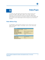
Status Pages
Status Software Page.................................................................................................................... 20
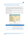
Status Connection Page ................................................................................................................ 21
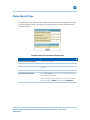
Status Security Page ..................................................................................................................... 22
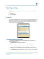
Status Diagnostics Page................................................................................................................ 23
Ping Utility ............................................................................................................................... 23
Traceroute Utility..................................................................................................................... 24
Status Event Log Page .................................................................................................................. 25
Status Configuration Page ............................................................................................................. 25
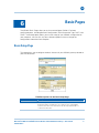
Basic Pages
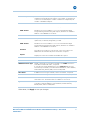
Basic Setup Page........................................................................................................................... 26
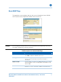
Basic DHCP Page .......................................................................................................................... 28
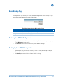
Basic DDNS Page .......................................................................................................................... 29
Basic Backup Page ........................................................................................................................ 30
Restoring Your SBG941 Configuration.................................................................................... 30
Backing Up Your SBG941 Configuration................................................................................. 30
Advanced Pages
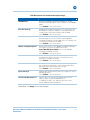
Advanced Options Page ................................................................................................................ 31
Advanced IP Filtering Page............................................................................................................ 33
Advanced MAC Filtering Page....................................................................................................... 34
Setting a MAC Address Filter ................................................................................................. 34
Advanced Port Filtering Page ........................................................................................................ 35
Advanced Port Forwarding Page ................................................................................................... 36
Advanced Port Triggers Page ........................................................................................................ 37
Advanced DMZ Host Page ............................................................................................................ 38
Setting Up the DMZ Host ....................................................................................................... 38
Advanced Routing Information Protocol Setup Page .................................................................... 39
Firewall Pages
Firewall Web Content Filter Page.................................................................................................. 42
Firewall Local Log Page................................................................................................................. 43
Firewall Remote Log Page ............................................................................................................ 44
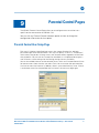
Parental Control Pages
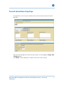
Parental Control User Setup Page ................................................................................................. 45
Parental Control Basic Setup Page ................................................................................................ 47
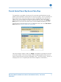
Parental Control Time of Day Access Policy Page ........................................................................ 48
Parental Control Event Log Page................................................................................................... 49
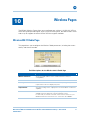
Wireless Pages
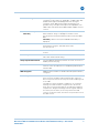
Wireless 802.11 Radio Page.......................................................................................................... 50

B
Motorola SURFboard SBG941 Series Wireless Cable Modem Gateways • User Guide viii
570280-001-a
Wireless 802.11 Primary Network Page ....................................................................................... 51
Wireless 802.11 Guest Network Page .......................................................................................... 54
Wireless 802.11 Advanced Page................................................................................................... 56
Wireless 802.11 Access Control Page .......................................................................................... 58
Wireless 802.11 Wi-Fi Multimedia Page ....................................................................................... 59
Wireless 802.11 Bridging Page ..................................................................................................... 61
Setting Up Your Wireless LAN ...................................................................................................... 62
Encrypting Wireless LAN Transmissions ................................................................................ 62
Installing Wireless Clients ............................................................................................................. 63
Configuring a Wireless Client for WPA ................................................................................... 63
Configuring a Wireless Client for WEP ................................................................................... 64
Configuring a Wireless Client with the Network Name (SSID)............................................... 64
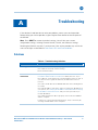
Troubleshooting
Solutions ........................................................................................................................................ 65
Front Panel LEDs and Error Conditions ......................................................................................... 66
Software License & Warranty
Software License........................................................................................................................... 67
Warranty Information..................................................................................................................... 68
Tab le s
Table 1 – SBG941 LED Activity During Startup ............................................................................... 7
Table 2 – Troubleshooting Solutions.............................................................................................. 65
Table 3 – Front Panel LEDs and Error Conditions.......................................................................... 66
Figures
Figure 1 – Cabling the SBG941........................................................................................................ 6
Figure 2 – Cabling the SBG941U ..................................................................................................... 8

B
Introduction • Inside the Box
Motorola SURFboard SBG941 Series Wireless Cable Modem Gateways • User Guide 1
570280-001-a
1
Introduction
The Motorola SBG941 Wireless Cable Modem Gateway can be used in households with
one or more computers capable of wireless and/or wired connectivity.
This guide provides product overview and setup information for the SBG941. It also
provides instructions for installing the cable modem and configuring the wireless,
Ethernet, router, DHCP, and security settings.
Note: All references to the SBG941 used throughout this guide also apply to the
SBG941U, SBG941E, and SBG941UE, unless noted otherwise. All SBG941U references
also apply to the SBG941UE unless noted otherwise.
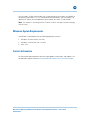
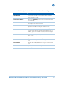
Inside the Box
Before installing the SBG941, verify that the following items are included in the box. If
you obtained the modem from your service provider, some of the included items may be
different.
Item Description
Power supply
Provides power via an AC electrical outlet
10/100Base-T Ethernet cable
Standard Cat 5, or higher, cable for connecting to
the network
Software License &
Regulatory Card
Contains software license, warranty, and safety
information for the SBG941
SBG941U Installation CD-
ROM
Contains the SBG941U Installation Assistant, and
this user guide
Included with SBG941U models only.
SBG941 Install Sheet
Provides basic information for setting up the
SBG941

B
Introduction • Minimum System Requirements
Motorola SURFboard SBG941 Series Wireless Cable Modem Gateways • User Guide 2
570280-001-a
You will need a 75-ohm coaxial cable with F-type connectors to connect the SBG941 to
the nearest cable outlet. If a TV is connected to the cable outlet, you may need a 5 to
900 MHz RF splitter and two additional coaxial cables to use the TV and SBG941.
Note: This product is also designed for IT power systems with phase to phase voltage
230VAC input.
Minimum System Requirements
The SBG941 is compatible with the following operating systems:
• Windows XP Service Pack 2 or later
• Windows Vista Service Pack 1 or later
• MAC 10.4
Contact Information
For information about Motorola consumer cable products, education, and support, visit
the Motorola support website at:
9http://broadband.motorola.com/consumers/support

B
Product Overview • Front Panel Overview
Motorola SURFboard SBG941 Series Wireless Cable Modem Gateways • User Guide 3
570280-001-a
2
Product Overview
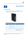
Front Panel Overview
The SBG941 front panel contains indicator lights and the WPS button, which is used to
configure a Wi-Fi Protected Security (WPS)-enabled device so that it automatically
connects to the SBG941 wireless network.
The SBG941 front panel LED indicators provide the following status information for
power, communications, and errors:
LED Flashing On
1 POWER
Not applicable — LED does not
flash
Green: Power is properly connected
2 RECEIVE
Scanning for a downstream
(receive) channel connection
Green: Downstream channel is connected
3 SEND
Scanning for an upstream (send)
channel connection
Green: Upstream channel is connected
4 ONLINE
Scanning for Internet connection Green: Startup process completed
5 LINK
Not applicable — LED does not
flash
Green: A device is connected to the
Ethernet (10Base-T) or Fast Ethernet
(100Base-T), and/or USB port.

B
Product Overview • Rear Panel Overview
Motorola SURFboard SBG941 Series Wireless Cable Modem Gateways • User Guide 4
570280-001-a
6 WIRELESS
Green: Wi-Fi enabled with
encrypted wireless data activity.
Long/short flash indicates mobile
pairing in progress.
Amber: Wi-Fi enabled with
unencrypted wireless data
activity.
Green: Wireless pairing successfully
established between the SBG941 and
another Wi-Fi enabled device on your
network — printer, PDA, laptop, etc.
Amber: Mobile pairing was successful.
LED turns green after five minutes.
7 WPS START
Not applicable — LED does not
flash
Green: WPS button is pressed and Wi-Fi
Protected Security is activated. LED will
remain on until WPS button is released.
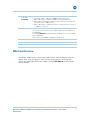
Rear Panel Overview
Both the SBG941 and SBG941U (shown above) rear panels contain the following cabling
port and connectors:
Item Description
1 ETHERNET
1 2 3 4
Ethernet-ports:
Activity LED — Green LED defines the activity of the Ethernet connector
• LED is ON — Indicates a 100Base-T negotiated data rate
• LED is FLASHING — Indicates activity is detected on the port
• LED is OFF — Indicates the unit is not powered or there is no 100Base-
T Ethernet connection

B
Product Overview • MAC Label Overview
Motorola SURFboard SBG941 Series Wireless Cable Modem Gateways • User Guide 5
570280-001-a
ETHERNET
1 2 3 4
(continued)
10/100 LED — Indicates the connection data rate
• Green LED is ON — Indicates a 100Base-T data connection
• Amber LED is ON — Indicates a 10Base-T negotiated data rate
• Amber LED is FLASHING — Indicates there is activity on the Ethernet
connection when in 10Base-T rate
• Amber LED is OFF— Indicates the device is not powered on or there is
no 10Base-T connection
2 USB
For Windows only, used for connecting a PC to the SBG941U.
You cannot connect a Macintosh or UNIX
®
computer to the USB port on
the SBG941U.
Front panel LINK LED will turn ON when a USB device is connected and a
link is established
USB connector is available on SBG941U models only.
3 CABLE
Coaxial cable connector
4 RESET
Resets the cable modem which may take from five to 30 minutes
5 POWER
+12VDC power connector
MAC Label Overview
The SBG941 Media Access Control (MAC) label contains the MAC address which is a
unique, 48-bit value that identifies each Ethernet network device. To receive data
service, you need to provide the MAC address marked HFC MAC ID to your Internet
Service provider.

B
Installing the Modem • Cabling the SBG941
Motorola SURFboard SBG941 Series Wireless Cable Modem Gateways • User Guide 6
570280-001-a
3
Installing the Modem
This section provides information on setting up and installing the SBG941 wireless
gateway. For information on the WLAN setup, see Setting Up Your Wireless LAN.
CAUTION This product is for indoor use only. Do not route the USB and/or Ethernet cable(s) outside of the
building. Exposure of the cables to lightning could create a safety hazard and damage the product.
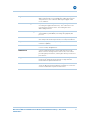
Cabling the SBG941
Before starting, power on your computer and check that the SBG941 is unplugged.
1. Connect the coaxial cable to the cable outlet or splitter.
2. Connect the other end of the coaxial cable to the cable connector on the modem.
Hand-tighten the connectors to avoid damaging them.
3. Plug the power cord into the Power port on the modem.
4. Plug the other end of the power cord into an electrical wall outlet.
The first time you plug in the modem, allow 5 to 30 minutes to find and lock on the
appropriate communications channels.
5. Connect the Ethernet cable to the Ethernet port on the computer.
6. Connect the other end of the Ethernet cable to the Ethernet port on the modem.
Figure 1 – Cabling the SBG941

B
Installing the Modem • Cabling the SBG941U
Motorola SURFboard SBG941 Series Wireless Cable Modem Gateways • User Guide 7
570280-001-a
7. Check that the LEDs on the front panel cycle through the following sequence:
Table 1 – SBG941 LED Activity During Startup
LED Description
POWER
Turns on when AC power is connected to the modem.
Indicates that the power is connected properly.
RECEIVE
Flashes while scanning for the downstream receive channel.
Changes to solid green when the receive channel is locked.
SEND
Flashes while scanning for the upstream send channel.
Changes to solid green when the send channel is locked.
ONLINE
Flashes during the modem registration and configuration.
Changes to solid green when the modem is registered.
Cabling the SBG941U
CAUTION Before plugging in the USB cable on the SBG941U, load the SBG941U Installation CD-ROM in the
CD-ROM drive.
Do not connect the Ethernet and USB cables on the same computer at any time.
Before starting, power on your computer and check that the SBG941U power cord is
unplugged.
1. Load and run the SBG941U Installation CD-ROM and install the applicable USB
driver.
2. Connect one end of the coaxial cable to the cable outlet or splitter.
3. Connect the other end of the coaxial cable to the cable connector on the modem.
Hand-tighten the connectors to avoid damaging them.
4. Plug the power cord into the power port on the modem.
5. Plug the other end of the power cord into an electrical wall outlet.
The first time you plug in the modem, allow it 5- to 30 minutes to find and lock on
the appropriate communications channels.
6. Connect the USB or Ethernet cable to the appropriate port on your computer.
7. Connect the other end of the USB or Ethernet cable to the appropriate port on the
modem.
8. Check that the LEDs on the front panel cycle through the proper sequence, see
Table 1 – SB
G941 LED Activity During Startup.

B
Installing the Modem • Connecting to the Internet
Motorola SURFboard SBG941 Series Wireless Cable Modem Gateways • User Guide 8
570280-001-a
Figure 2 – Cabling the SBG941U
Connecting to the Internet
After installing the modem, check that you can connect to the Internet. You can retrieve
an IP address for your computer’s network interface using one of the following options:
• Retrieve the statically-defined IP address and DNS address
• Automatically retrieve the IP address using the Network DHCP server
The modem provides a DHCP server on its LAN. Motorola recommends that you
configure your LAN to obtain the IPs for the LAN and DNS server automatically.
Make sure all computers on your LAN are configured for TCP/IP. After configuring TCP/IP
on your computer, you should verify the IP address.
Note: For UNIX or Linux systems, follow the instructions in the applicable user
documentation.
Configuring TCP/IP in Windows XP
1. Open the Control Panel.
2. Double-click Network Connections to list the Dial-up and LAN or High-Speed
Internet connections.
3. Right-click the network connection for your network interface.

B
Installing the Modem • Connecting to the Internet
Motorola SURFboard SBG941 Series Wireless Cable Modem Gateways • User Guide 9
570280-001-a
4. Select Properties from the drop-down menu to display the Local Area Connection
Properties window. Be sure Internet Protocol (TCP/IP) is checked.
5. Select Internet Protocol (TCP/IP) and click Properties to display the Internet
Protocol (TCP/IP) Properties window.
6. Select Obtain an IP address automatically and Obtain DNS server address
automatically.
7. Click OK to save the TCP/IP settings and exit the TCP/IP Properties window.
8. Close the Local Area Connection Properties window and then exit the Control Panel.
9. When you complete the TCP/IP configuration, go to Verifying the IP Address in
Windo
ws XP.
Configuring TCP/IP in Windows Vista
1. Open the Control Panel.
2. Double-click Network and Internet to display the Network and Internet window.
3. Double-click Network and Sharing Center to display the Network and Sharing
Center window.
4. Click Manage network connections to display the LAN or High-Speed Internet
connections window.
5. Right-click the network connection for your network interface.
6. Select Properties to display the Local Area Connection Properties window.
Vista may prompt you to allow access to the Network Properties Options. If you see
the prompt,
User Account Control -- Windows needs your permission to
continue
, click Continue.
7. Select Internet Protocol Version 4 or 6 (TCP/IPv4 or v6) and click Properties to
display the Internet Protocol Properties window.
8. Select Obtain an IP address automatically and Obtain DNS server address
automatically.
9. Click OK to save the TCP/IP settings and close the Internet Protocol Version 4
(TCP/IPv4) Properties window.
10. Click OK to close the Local Area Connection Properties window.
11. Close the remaining windows and exit the Control Panel.
12. When you complete the TCP/IP configuration, go to Verifying the IP Address in
Windo
ws Vista.

B
Installing the Modem • Connecting to the Internet
Motorola SURFboard SBG941 Series Wireless Cable Modem Gateways • User Guide 10
570280-001-a
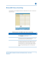
Verifying the IP Address in Windows XP
To check the IP address:
1. On the Windows Desktop, click Start.
2. Select Run. The Run window is displayed.
3. Type cmd and click OK.
4. Type ipconfig and press ENTER to display your IP configuration.
If an Autoconfiguration IP address is displayed, that indicates possible broadband
network problems or an improper connection between your computer and the SBG941.
The Autoconfiguration IP address, ranging from 169.254.0.0 to 169.254.255.255, is
reserved for Automatic Private IP Addressing (APIPA).
This can occur if the modem is configured to automatically obtain an IP address from a
Dynamic Host Configuration Protocol (DHCP) server. When Auto-configuration is
enabled, Windows will automatically assign an IP address if the cable modem gateway is
unable to obtain one. Because this automatically assigned IP address is not valid, you will
not be able to access the Internet using the cable modem gateway.
Check the following:
• Your cable connections
• Whether you can see cable-TV channels on your television
After successfully verifying your cable connections and proper cable-TV operation, you
can renew your IP address.
Verifying the IP Address in Windows Vista
Do the following to verify the IP address:
1. On the Windows Desktop, click Start.
2. Click All Programs.
3. Click Accessories.
4. Click Run to display the Run window.
5. Type cmd and click OK to open a command prompt window.
6. Type ipconfig and press ENTER to display the IP Configuration.
If an Auto-configuration IP address is displayed, that indicates possible broadband
network problems or an improper connection between your computer and the SBG941.
The Auto-configuration IP address, ranging from 169.254.0.0 to 169.254.255.255, is
reserved for Automatic Private IP Addressing (APIPA).

B
Installing the Modem • Setting Up a Wi-Fi Network
Motorola SURFboard SBG941 Series Wireless Cable Modem Gateways • User Guide 11
570280-001-a
Renewing Your IP Address in Windows XP or Windows Vista
1. Open a command prompt window.
A. From the Windows Taskbar, click Start to open the Start menu.
B. Select Run to open the Run window.
C. Type cmd in the Open entry box and click OK.
2. Type ipconfig /renew and press ENTER. A valid IP address should appear
indicating that Internet access is available.
3. Type exit and press ENTER to close the command prompt window.
If, after performing this procedure, your computer cannot access the Internet, call your
cable provider for help.
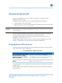
Setting Up a Wi-Fi Network
Do the following to set up a Wi-Fi network using the WPS button on the modem:
1. If necessary, power on the modem.
2. Power on the WPS-enabled devices you want to have access to the network, such
as a PC or router.
The Wi-Fi network will automatically detect the WPS devices.
3. Press WPS button on the modem.
4. If applicable, press WPS button on the other WPS devices.
Wall Mounting the Modem
If you choose to wall mount the modem, do the following before starting:
• Locate the unit as specified by the local or national codes governing residential or
business cable TV and communications services.
• Follow all local standards for installing a network interface unit/network interface
device (NIU/NID).
• Make sure the AC power plug is disconnected from the wall outlet and all cables are
removed from the back of the modem before starting the installation.
• Determine if you are mounting the modem horizontally or vertically.
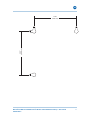
• Use M3.5 x 38 mm (#6 x 1½ inch) screws with a flat underside and maximum screw
head diameter of 9.0 mm to mount the modem.
See the screw mounting dimensions below to properly mount the modem:

B
Installing the Modem • Wall Mounting the Modem
Motorola SURFboard SBG941 Series Wireless Cable Modem Gateways • User Guide 12
570280-001-a
If possible, mount the modem to concrete, masonry, a wooden stud, or some other solid
wall material. Use anchors if necessary (for example, if you must mount the unit on
drywall).
CAUTION Before drilling holes, check the structure for potential damage to water, gas, or electrical lines.
1. Drill the holes to a depth of at least 1½ inches (3.8 cm).
There must be .10 inches (2.5 mm) between the wall and the underside of the screw
head.
2. After mounting, reconnect the coaxial cable and re-plug the power cord.
3. Properly route the cables to avoid any safety hazards.
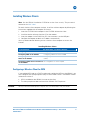
Wall Mounting Template
You can print the following page to use as a wall mounting template.
After mounting the modem, do the following:
1. Reconnect the coaxial cable input and Ethernet connection.
2. Plug the power cord into the +12VDC Power connector on the modem and the
electrical outlet.
3. Arrange the cables appropriately to prevent any safety hazards.
Page is loading ...
Page is loading ...
Page is loading ...
Page is loading ...
Page is loading ...
Page is loading ...
Page is loading ...
Page is loading ...
Page is loading ...
Page is loading ...
Page is loading ...
Page is loading ...
Page is loading ...
Page is loading ...
Page is loading ...
Page is loading ...
Page is loading ...
Page is loading ...
Page is loading ...
Page is loading ...
Page is loading ...
Page is loading ...
Page is loading ...
Page is loading ...
Page is loading ...
Page is loading ...
Page is loading ...
Page is loading ...
Page is loading ...
Page is loading ...
Page is loading ...
Page is loading ...
Page is loading ...
Page is loading ...
Page is loading ...
Page is loading ...
Page is loading ...
Page is loading ...
Page is loading ...
Page is loading ...
Page is loading ...
Page is loading ...
Page is loading ...
Page is loading ...
Page is loading ...
Page is loading ...
Page is loading ...
Page is loading ...
Page is loading ...
Page is loading ...
Page is loading ...
Page is loading ...
Page is loading ...
Page is loading ...
Page is loading ...
Page is loading ...
Page is loading ...
Page is loading ...
-
 1
1
-
 2
2
-
 3
3
-
 4
4
-
 5
5
-
 6
6
-
 7
7
-
 8
8
-
 9
9
-
 10
10
-
 11
11
-
 12
12
-
 13
13
-
 14
14
-
 15
15
-
 16
16
-
 17
17
-
 18
18
-
 19
19
-
 20
20
-
 21
21
-
 22
22
-
 23
23
-
 24
24
-
 25
25
-
 26
26
-
 27
27
-
 28
28
-
 29
29
-
 30
30
-
 31
31
-
 32
32
-
 33
33
-
 34
34
-
 35
35
-
 36
36
-
 37
37
-
 38
38
-
 39
39
-
 40
40
-
 41
41
-
 42
42
-
 43
43
-
 44
44
-
 45
45
-
 46
46
-
 47
47
-
 48
48
-
 49
49
-
 50
50
-
 51
51
-
 52
52
-
 53
53
-
 54
54
-
 55
55
-
 56
56
-
 57
57
-
 58
58
-
 59
59
-
 60
60
-
 61
61
-
 62
62
-
 63
63
-
 64
64
-
 65
65
-
 66
66
-
 67
67
-
 68
68
-
 69
69
-
 70
70
-
 71
71
-
 72
72
-
 73
73
-
 74
74
-
 75
75
-
 76
76
-
 77
77
-
 78
78


Motorola SURFboard 570280-001-a User manual
- Category
- Modems
- Type
- User manual
- This manual is also suitable for
Ask a question and I''ll find the answer in the document
Finding information in a document is now easier with AI
Related papers
-
Motorola RSG2500 User manual
-
-
-
-
-
 ARRIS Group SURFboard SVG1202 User manual
-
-
-
-


