Page is loading ...

INSTALLATION INSTRUCTIONS
PRODUCT SAFETY & LEGAL DISCLAIMER
•IMPORTANT READ ALL INSTRUCTIONS CAREFULLY BEFORE INSTALLING, FAILURE TO DO SO
MAY CAUSE PERSONAL INJURY OR DAMAGE TO PRODUCT AND/OR PROPERTY.
•Review the product package and contents prior to beginning the installation. Take care when
opening the packaging and removing items. If a return is needed you will want to return the product in
its original packaging if possible.
•This instruction guide is provided as a GENERAL installation guide, some vehicles vary dimensionally
and may require additional steps.
•Test fit the product on the vehicle prior to any third party modifications and or finishing. The
manufacturer and/or distributors do not accept responsibility for third party charges, labor and or
third part replacement modifications. Some modifications may void the factory warranty.
•Exercise due-diligence when installing this product. The manufacturer and distributors of this product
do not accept any responsibility for vehicle damage or personal injury resulting from the installation of
this product. Careless installation and operation can result in serious injury or equipment damage.
•This product is for general off-road use. All liability for installation and use rests with the
owner/operator.
•INSTALLER: Once installation is complete, please return this guide along with other documentation
included in this product back to the consumer for future reference. The manufacturer/distributors of
this product do not guarantee this particular version will be available at a later date.
PART NO.
●230121T
PRODUCT DESCRIPTION:
●TRAILLINE FRONT WINCH
BUMPER-FULL
APPLICATION:
●JEEP WRANGLER JK & JL

INJURY HAZARD
Please complete a shop and tool inspection prior to beginning the installation.
•Always make sure you have a clean, dry and well lit work area.
•Always remove jewelry, loose fitting clothing and wear protective gloves and eye protection.
•Always use extreme caution when jacking or raising a vehicle for work. Set the emergency
brake and use tire/wheel blocks and jack stands. Refer to the vehicle manufacturer hand
book. Utilize the vehicle manufacturers designated lifting points.
•Always use appropriate and adequate care in lifting parts during disassembly and
installation. Seek help in lifting heavy or large items into place. Utilize jacks and or lifting
devices when available.
•Always insure products are secure during disassembly and installation.
•Always wear eye protection and take steps to protect any exposed skin during the
installations. Drilling, cutting and grinding plastic and metal may create flying particles that
can cause injury.
•Always use extreme caution when drilling, cutting and or grinding on a vehicle. Thoroughly
inspect the area to be drilled, on both sides of material, prior to modification and relocate any
objects that may become damaged.
•Always assemble and tighten all fasteners per the installation instructions.
•Always route electrical cables carefully. Avoid moving parts, parts that may become hot and
rough or sharp edges.
•Always insulate and protect all exposed wiring and electrical connections.
INSTALLATION INSTRUCTIONS
MAINTENANCE AND CARE
•Always perform regular inspections and maintenance on mounts and related fasteners.
•Periodically check and tighten all fasteners.
•Stripped, fractured, or bent fasteners must be replaced.
•After washing the vehicle make sure to fully dry all surfaces.
•In areas with cold temperatures make sure to wash the product often to remove harmful
materials used on road ways.
•Never use abrasive cleaners or polish compounds. Clean with a gentle soap and water. If you
use wax use a non-abrasive automotive wax such as pure carnauba wax.
WARNING
Some products have been designed to work together with factory rear sensor systems, factory forward
facing sensor systems and factory air bags.
•Installation of some of these products may alter the factory sensor system performance.
•Factory sensors may read shackles or hooks protruding from the fairlead and or tow hooks.
•All sensor testing is completed by Go Rhino Products and or third party testing labs on modified
vehicles.
•Sensor sensitivity, factory sensor housing, orientation, and operating conditions are all variables that
will influence functionality of the sensors.
•Installation of some product may effect the factory air bag systems.
•Some products allow the use of third party products such as winches, shackles, hooks, etc. Follow the
respective manufacturers operating instructions for use with our products.
•Make sure to fully understand the product, it’s intended use and operation prior to use.
•Above all… be safe!

INSTALLATION INSTRUCTIONS
1 1/2 hrs.
•Inch & Metric Sockets / Ratchet, Ratchet Extensions & Swivel Joint Adapter
•Inch & Metric Wrenches
•Slotted Screw Driver or Panel clip removal tool
•5/32” Hex Key
•Drill Motor & ½” Drill Bit
ESTIMATED TIME FOR INSTALLATION:
PARTS INCLUDED IN THIS LIST:
Go Rhino recommends you, the installer, read this installation instruction manual from front to back before
installing the product.
TOOLS NEEDED FOR INSTALLATION:
ITEM
QTY.
DESCRIPTION
ITEM
QTY.
DESCRIPTION
A 6 1/4” x 3/4” Button Head Hex Drive Screw I 8 1/2" Lock Washer
B 6 1/4” Flat Washer (Plastic) J 16 1/2" Flat Washer
C 6 1/4” Lock Washer K 8 1/2” Hex Nut
D 6 1/4” Hex Nut L 2 Frame Bracket
E 6 Offset Clip M 1 Trail line Front Winch Bumper-Full
F 2 3/8” Hex Nut N 1 Removable Center Cover (Pre-Installed)
G 8 1/2” x 1 ½” Flange Head Bolt 0 2 Mesh Cover (Pre-Installed)
H 8 1/2” X 1 1/2” Carriage Bolt P 1 Gear Drawer (Pre-Installed)

INSTALLATION INSTRUCTIONS
Wrangler JL OEM Bumper Removal
Step-1 Open the hood and disconnect the vehicle battery or batteries.
Step-2 On the passenger side, disconnect the bumper wire harness from the vehicle wire harness,
(FIGURE 1).
FIGURE 1
Bumper Wire Harness
Passenger Side

INSTALLATION INSTRUCTIONS
Step-3 Using an 8mm socket, remove (1) hex bolt on each side of the vehicle securing the air dam to
the metal shield behind the air dam, (FIGURE 2).
FIGURE 2
Hex Bolts
Air Dam

INSTALLATION INSTRUCTIONS
Step-4 Using a slot screwdriver or panel clip removal tool, remove the (8) plastic push pins securing
the air dam to the bumper, (FIGURE 3). Remove the air dam from the vehicle.
FIGURE 3
Air Dam
Plastic Push Pin

INSTALLATION INSTRUCTIONS
Step-5 Using a 16mm socket remove, the (2) hex bolts securing the metal shield to the frame, (FIGURE
4). Remove the metal shield from the vehicle.
FIGURE 4
Metal Shield
Hex Bolts

INSTALLATION INSTRUCTIONS
Step-6 on each side of the vehicle, use a slot screwdriver or panel clip removal tool and remove (1)
plastic push pin securing the frame cover to the frame rail, (FIGURE 5).
FIGURE 5
Frame Cover
Plastic Push Pin

INSTALLATION INSTRUCTIONS
Step-7 On each side of the vehicle, use an 18mm socket and remove the (2) hex nuts from the studs on
each side of the vehicle frame securing the OEM front bumper to the frame, (FIGURE 6 & 7).
FIGURE 7
FIGURE 6
Driver Side (inner)
Driver Side (outer)
Hex Nuts
Hex Nuts

INSTALLATION INSTRUCTIONS
Step-8 With assistance remove the OEM front bumper from the vehicle.
Step-9 On each side of the vehicle. drill the OEM bumper mounting bracket holes to 1/2“, (FIGURE 8).
FIGURE 8
OEM Bumper
Mounting Brackets

INSTALLATION INSTRUCTIONS
Wrangler JK OEM Bumper Removal
Step-1 Open hood and disconnect the vehicle battery or batteries.
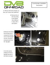
Step-2 Begin by using a slotted screwdriver, pry and remove the (4) plastic push pins securing the
front of the air dam to the bottom of the factory bumper, (FIGURE 1 & 2).
FIGURE 1
Plastic Push Pin
Air Dam
FIGURE 2

INSTALLATION INSTRUCTIONS
Step-3 Remove the (2) plastic pushpins securing the rear of the air dam to the frame cross member,
and remove the air dam from the underside of the vehicle, (FIGURE 3).
FIGURE 3
Plastic Push Pin
Plastic Push Pin
Air Dam

INSTALLATION INSTRUCTIONS
Step-4 If equipped, disconnect the wiring harness from the fog lights and unclip the cable ties securing
the wiring harness to the factory bumper, (FIGURE 4 & 5).
FIGURE 4
FIGURE 5
Wire Harness
Cable Tie

INSTALLATION INSTRUCTIONS
Step-5 On each side of the vehicle, remove the (4) hex nuts from the studs securing the factory bumper
to the frame using an18mm socket, (Figure 6 & 7). Note: Remove (4) backing plates behind the nuts
and save for installation with supplied frame brackets.
FIGURE 6
FIGURE 7
Passenger Side
Backing Plate
Hex Nuts
Hex Nuts Backing Plate
Passenger Side

INSTALLATION INSTRUCTIONS
Step-6 With assistance remove the factory bumper from the vehicle and set aside.
Step-7 Using a Phillips screwdriver remove the (2) fastener securing the frame cover to the top of the
frame, (FIGURE 8 & 9). Remove the cover from the vehicle.
Frame Cover
FIGURE 8
FIGURE 9
Plastic Push Pin

INSTALLATION INSTRUCTIONS
Step-8 Using a 10mm socket remove the (2) screws securing the vacuum canister to the frame bracket.
Lift and rotate the canister clockwise 180 degrees, then place (1) 3/8” hex nut under each of the canisters
mounting flanges and reinstall, and tighten the screws, (FIGURE 10 & 11).
FIGURE 11
FIGURE 10
Vacuum Canister
Driver Side
FF
Vacuum Canister Screws
Vacuum Canister Screws
Vacuum Canister

INSTALLATION INSTRUCTIONS
Trailline Bumper Installation JL & JK
Step-1 Position the passenger side frame bracket up to the end of the frame, align the holes in the frame bracket
with the holes in the frame and secure the frame bracket to the frame using (4) ½” X 1 ½” carriage bolts, (4) ½”
flat washers, (4) ½” lock washers and (4) ½” hex nuts. bolts, (FIGURE 1 & 2). Leave the nuts and bolts loose for
final adjustment. Note: JK models, reinstall the (2) OEM bumper backing plates prior to installing the ½”
washers and nuts. Repeat to install the driver side frame bracket.
FIGURE 1
FIGURE 2
Passenger Side
Passenger Side
H
J-I
K
L
L

INSTALLATION INSTRUCTIONS
Step-2 If equipped, remove the fog lights from the OEM bumper.
Step-3 From the back of the Trailine front winch bumper, position one of the factory fog lights so the top of the
lens aligns with notch and the lens protrudes out through the opening in the fog light mounting plate, (FIGURE
3).
Step-4 Assemble and attach the fog light housing to the fog light mounting plate using (3) of the offset mount
clips (3) ¼” x 3/4” button head screws, (3) ¼” plastic flat washers, (3) ¼” Lock washers and (3) ¼” hex nuts,
(FIGURE 3). Repeat step 3 and 4 to install the remaining fog light on the passenger side of the Trailline front
winch bumper.
FIGURE 3
A-B-
C-D
E
Driver Side
OEM Fog Light
Fog Light Mounting plate

INSTALLATION INSTRUCTIONS
Step-5 The pre-installed mesh front covers need to be removed using hand tools to slowly remove the screws,
(FIGURE 4). Using an air assisted impact or ratchet will damage the screw threads and the internal nut assembly
in the bumper shell. Use of an appropriate anti-seize compound is highly recommended for re-installation.
O
FIGURE 4

INSTALLATION INSTRUCTIONS
Step-6 With assistance lift the Trailline front winch bumper up to the vehicle, align the holes in the face of the
bumper with the weld nuts on the frame brackets and secure the bumper to each frame bracket using (4) ½” x 1
1/2” flange head bolts and (4) ½” flat washers, (FIGURE 5). adjust and hold the bumper visual alignment
position, then tighten the bolts securing the bumper to the frame brackets then tighten the nuts and bolts
securing the frame brackets to the vehicle frame.
Step-7 Reinstall the mesh front covers to the Trailline front winch bumper using the ¼” x ¾” button head hex
drive screws and plastic flat washers removed in step-7, (FIGURE 6).
FIGURE 5
FIGURE 6
Passenger Side
Passenger Side
G-J
O
G-J
A-B
A-B
/