Page is loading ...

INSTALLATION GUIDE
XR150/XR550 INTERNATIONAL
SERIES CONTROL PANEL

Digital Monitoring Products XR150INT/XR550INT Series Installation Guide
MODEL XR150/XR550 INTERNATIONAL SERIES PANELS
INSTALLATION GUIDE
© 2021 Digital Monitoring Products, Inc.
Information furnished by DMP is believed to be accurate and reliable.
This information is subject to change without notice.

XR150INT/XR550INT Series Installation Guide Digital Monitoring Products
i
TABLE OF CONTENTS
Product Specications Summary
1.1 Power Supply ..................................................................................................... 1
1.2 Communication ................................................................................................... 1
1.3 Panel Zones ........................................................................................................ 1
1.4 Keypad Bus ........................................................................................................ 1
1.5 LX500-LX900 Bus™ ............................................................................................. 1
1.6 Outputs .............................................................................................................. 1
1.7 EnclosureSpecications ...................................................................................... 2
Panel Features
2.1 Description ......................................................................................................... 2
2.2 Zone Expansion .................................................................................................. 2
2.3 Output Expansion ............................................................................................... 2
2.4 Central Station Communication ............................................................................ 2
2.5 Caution Notes ..................................................................................................... 3
2.6 Compliance Instructions ...................................................................................... 3
System Components
3.1 SpecicandNon-specicWiredInterconnections .................................................. 4
3.2 Lightning Protection ............................................................................................ 4
3.3 Accessory Devices ............................................................................................... 5
Installation
4.1 Mounting the Enclosure ....................................................................................... 6
4.2 Mounting Keypads and Zone Expansion Modules ................................................... 7
4.3 Connecting LX-Bus™, AX-Bus™ and Keypad Bus Devices ....................................... 8
4.4 WirelessKeypadAssociation ................................................................................ 8
5.1 AC Terminals 1 and 2 .......................................................................................... 9
5.2 50VA-75VA 3-Pin Header for Transformer Types .................................................... 9
Secondary Power Supply
6.1 Battery Terminals 3 and 4 .................................................................................... 9
6.2 Earth Ground (GND) ........................................................................................... 9
6.3 Battery Only Restart ............................................................................................ 9
6.4 Battery Replacement Period ................................................................................. 9
6.5 Discharge/Recharge ............................................................................................ 9
6.6 Battery Supervision ............................................................................................10
6.7 BatteryCuto ....................................................................................................10
6.8 Power Requirements ..........................................................................................10
6.9 Standby Battery Selection ...................................................................................12
Bell Output
7.1 Terminals 5 and 6 ..............................................................................................13
Keypad Bus
8.1 Description ........................................................................................................13
8.2 Terminal 7 - RED................................................................................................13
8.3 Terminal8-YELLOW .........................................................................................13
8.4 Terminal 9 - GREEN ...........................................................................................13
8.5 Terminal 10 - BLACK ..........................................................................................13
8.6 Programming (PROG) Connection .......................................................................13
8.7 Keypad Bus LEDs ...............................................................................................13
8.8 OVC LED(s) .......................................................................................................13
Smoke and Glassbreak Detector Output
9.1 Terminals 11 and 12 ...........................................................................................14
9.2 Current Rating ...................................................................................................14

Digital Monitoring Products XR150INT/XR550INT Series Installation Guide
ii
TABLE OF CONTENTS
Protection Zones
10.1 Terminals 13–24 ................................................................................................14
10.2 Operational Parameters ......................................................................................14
10.3 Zone Response Time ..........................................................................................15
10.4 Keyswitch Arming Zone ......................................................................................15
Powered Zones for 2-Wire Smoke Detectors
11.1 Terminals 25–26 and 27–28 ................................................................................15
Dry Contact Relay Outputs
12.1 Description ........................................................................................................15
12.2 Contact Rating ...................................................................................................15
12.3 Model431OutputHarnessWiring .......................................................................16
Annunciator Outputs
13.1 Description ........................................................................................................16
13.2 Model300HarnessWiring ..................................................................................16
13.3 Model 860 Relay Module .....................................................................................16
Wireless Bus Expansion
14.1 Description ........................................................................................................16
14.2 WirelessBusLEDs .............................................................................................16
LX-BusTM/AX-BusTM Expansion
15.1 LX-Bus HeadersLX-Bus/AX-Bus Headers ...............................................................17
15.2 LX-Bus/AX-Bus LEDs ..........................................................................................17
15.3 OVC LEDs ..........................................................................................................18
ETHERNET Connector (Panels with Network only)
16.1 Description ........................................................................................................18
16.2 Ethernet LEDs ...................................................................................................18
16.3 Network Transient Suppression ...........................................................................18
PHONE LINE RJ Connector
17.1 Description ........................................................................................................18
17.2 Phone Line Monitor ............................................................................................18
RESET and TAMPER Headers
18.1 RESET Header ...................................................................................................19
18.2 TAMPER Header .................................................................................................19
Cellular Modules
19.1 CELL MODULE Header ........................................................................................20
19.2 Module Installation ............................................................................................20
19.3 Connecting the Antenna .....................................................................................20
International Certications

XR150INT/XR550INT Series Installation Guide Digital Monitoring Products
1
PANEL SPECIFICATIONS
Product Specications Summary
1.1 Power Supply
Transformer Input: Model 324INT wire-in — Primary input: 230 VAC, 50 Hz, Secondary output: 18 VAC 100
VA, 400 mA
Standby Battery: 12 VDC, 1.0 Amps Max. charging current
Models 365, 366, 368, or 369
Replace every 3 to 5 years
Auxiliary: 12 VDC output at 1.5 Amp Max
Bell Output: 12 VDC at 1.5 Amp Max
All circuits are inherent Power Limited except the red battery wire and AC terminal.
1.2 Communication
• Built-in network communication to DMP Model SCS-1R or SCS-VR Receivers
• Built-in Contact ID communication to DMP Model SCS-1R Receivers
• Can operate as a local panel
1.3 Panel Zones
• Eight 1k Ohm EOL/Dual EOL burglary zones (zones 1 to 8)
• Two 3.3k Ohm EOL powered zone with reset (zones 9 and 10)
1.4 Keypad Bus
You can connect up to a total of 16 of the following supervised keypads and expansion modules to keypad
bus:
• Alphanumeric keypads
• One, four, eight, and sixteen-zone expansion modules
• Wireless Keypads (maximum of 7)
1.5 LX500-LX900 Bus™
You can connect the following devices to the LX-Bus™ connections provided on the panel. See Accessory
Devices section 3.3.
• Four, eight, sixteen- and/or single-zone expansion modules
• Relay output expansion modules
• Graphic annunciator modules
1.6 Outputs
The XR150INT/XR550INT Series panels provide two Single Pole, Double Throw (SPDT) relay outputs which
require the installation of two Model 305 relays, each rated 1 Amp at 30 VDC resistive (power limited sources
only).
A Model 431 Output Harness is required to use these outputs.
The XR150INT/XR550INT Series panels also provide four open collector outputs rated for 50mA each. The
open collector outputs provide ground connection for a positive voltage source. A Model 300 Output Harness
is required to use these outputs.

Digital Monitoring Products XR150INT/XR550INT Series Installation Guide
2
PANEL SPECIFICATIONS
1.7 Enclosure Specications
The XR150INT/XR550INT Series panels are shipped in an enclosure with a transformer, End-of-Line resistors,
battery leads, user guide, and programming sheets.
Enclosure
Model
Size Color(s) Construction (Cold
Rolled Steel)
350INT 44.45 W x 34.29 H x 8.89 D cm Gray (G) or Red (R) 18-Gauge
350AINT 44.45 W x 34.29 H x 8.89 D cm Gray (G) 18-Gauge with
16-Gauge door
349INT 31.75 W x 29.21 H x 8.89 D cm Gray (G) 20-Gauge
352PINT 36.83 W x 81.28 H x 10.16 D cm Gray (G) 16-Gauge
352XINT 36.83 W x 81.28 H x 10.16 D cm Gray (G) 16-Gauge
Panel Features
2.1 Description
The DMP XR150INT/XR550INT Series system is made up of an alarm panel with a built-in communicator, an
enclosure, battery, one transformer, and keypads. Each panel is a versatile 12VDC, combined access control,
burglary, and re communicator panel with battery backup. The panels provide eight on-board burglary zones
and two on-board 12 VDC Class B powered zones. The powered zones have a reset capability to provide for 2-wire
smoke detectors, relays, or other latching devices. Combined current requirements of additional modules may
require an auxiliary power supply. Refer to the Power Requirements section in this guide when calculating power
requirements. The panels can communicate to DMP SCS-1R Receivers using digital dialer, cellular, network, or
Contact ID communication. Panels using cellular, network, or encrypted communication can also communicate to
DMP SCS-VR Receivers.
2.2 Zone Expansion
Each panel provides multiple options for zone expansion:
• 10 on-board zones
• Up to 64 programmable keypad zones
• Up to 500 LX-Bus zones
Using DMP LCD keypad remote zone capability and zone expansion modules, additional zones are available on each
panel:
• XR550INT provides up to 574 additional zones
• XR150INT provides up to 142 additional zones
The panel keypad data bus supports up to 16 supervised device addresses with each address supporting up to four
programmable expansion zones (64 total).
Using the on board LX-Bus™ connections, and any combination of single, four, eight, or sixteen-zone expansion
modules and single-zone LX-Bus™ detectors, additional zones are available on each panel:
• XR550INT provides up to 500 additional zones (LX500-LX900)
• XR150INT provides up to 100 additional zones (LX500)
Note: Do not use shielded or twisted pair wiring for LX-Bus or Keypad Bus circuits.
2.3 Output Expansion
In addition to the two SPDT relays and four programmable open collector outputs on the XR150INT/XR550INT
Series panels, you can also connect up to 25 programmable Model 716 Output Expansion Modules to each LX-Bus.
These modules can provide an additional 500 or 100 programmable SPDT relays.
The panels provide Output Schedules for programming the 716 to perform a variety of annunciation and control
functions. Also assign the 716 outputs to any panel Output Options such as Fire Alarm, Communication Fail, or
Phone Trouble Outputs. Refer to the 716 Installation Guide (LT-0183).
2.4 Central Station Communication
You can program the panel for reporting to DMP SCS-VR or SCS-1R Receivers using digital dialer, cellular, network,
or Contact ID communication. The panels connect at the premises to a standard RJ31X or RJ38X telephone jack.

XR150INT/XR550INT Series Installation Guide Digital Monitoring Products
3
PANEL SPECIFICATIONS
2.5 Caution Notes
Throughout this guide you will see caution notes containing information you need to know when installing the
panel. These cautions are indicated with a yield sign. Whenever you see a caution note, make sure you completely
read and understand its information. Failing to follow the caution note can cause damage to the equipment or
improper operation of one or more components in the system. See the example shown below.
Always ground the panel before applying power to any devices: The panel must be properly grounded
before connecting any devices or applying power to the panel. Proper grounding protects against Electrostatic
Discharge (ESD) that can damage system components.
2.6 Compliance Instructions
For applications that must conform to a local authorities installation standard or a National Recognized Testing
Laboratory certicated system, please see the Compliance Listing Guide LT-1330INT for additional instructions.

Digital Monitoring Products XR150INT/XR550INT Series Installation Guide
4
SYSTEM COMPONENTS
System Components
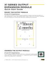
3.1 Specic and Non-specic Wired Interconnections
The XR150INT/XR550INT Series panels diagram below shows some of the accessory modules you can connect
for use in various applications. A brief description of each module follows in section 3.3.
AC
1 2 3 4 5 6 7 8 10 11 12 13 14 15 16 17 18 199 20 21 22 23 24 25 26 27 28
+B BELLGND SMK GNDRED YEL GRN BLK Z1 Z2 Z3 Z4 Z5 Z6 Z7 Z8 Z9+ Z9– Z10+ Z10–AC –B GND GND GNDGND
Auxiliary Power
Total current combined from terminals
7, 11, 25, 27, XBUS and LX500-LX900
1.5 Amp Max 13.8 VDC to 10.2 VDC
LX800
LX900
J4
Tamper
K6 K7
Output 1 Output 2
J3
Phone Line
Battery
Start
J8
J16
Reset
Out1 Out2
Outputs 3-6
J11
3
4
5
6
J2
OVC
XR550INT Series
International Panel
LX500
LX700
XBUS
J13
J14 J9 J15 J19J17
J24
Form C Relays (J2)
Output Color Code–Model 431 Harness
Output 2 N/O Orange/White
Output 2 Com White/Gray
Output 2 N/C Violet/White
Output 1 N/O Orange
Output 1 Com Gray
Output 1 N/C Violet
Annunciator Outputs (J11)
Output Color Code
Output 3 Red
Output 4 Yellow
Output 5 Green
Output 6 Black
s
s
J12 75VA
50VA
Listed Resistors
1.0k Ohm - DMP Model 311
3.3k Ohm - DMP Model 309
10K Ohm - DMP Model 308
LX600
Tamper
16 to 18 gauge wire
Maximum AC Wire distance
with 16 gauge wire: 70 feet
with 18 gauge wire: 40 feet
RED
BLACK
Cold Water
Pipe Earth
Ground
Bell
3.3k Ohm
Resistor
DMP
Model 309
3.3k Ohm
Resistor
DMP
Model 309
s
= Supervised Circuit
Zone
9
Zone
10
22 gauge minimum
22 gauge minimum
22 gauge minimum
22 gauge minimum
RED
YELLOW
GREEN
BLACK
Zone Expander
Models 714-8INT,
714-16INT
20mA @ 12 VDC
RED
YELLOW
GREEN
BLACK
s
Dual
1k
Ohm
Zone Expander
(up to 8 zones)
Model 712-8INT
19mA @ 12 VDC
1k
Ohm
Earth Ground
s s s s
sss
s
s
s
s
s
s
¼"
AC Wiring must be in conduit and exit
out the left side of the enclosure.
Wiring on terminals 5 through 22 must
exit right and maintain 1/4" separation
from the AC and battery positive wiring.
Dual
1k
Ohm
Dual
1k
Ohm
Dual
1k
Ohm
Dual
1k
Ohm
Dual
1k
Ohm
Dual
1k
Ohm
Dual
1k
Ohm
ssssssss
ssssssss
Dual
1k
Ohm
ss
Dual
1k
Ohm
ss
Dual
1k
Ohm
ss
Dual 1k
Ohm
ss
s
Model 324INT 230V 100VA
18 VAC, 50 Hz,
400 mA
CAUTION: DO NOT USE LOOPED WIRE
UNDER TERMINALS. BREAK WIRE RUN
TO PROVIDE SUPERVISION OF
CONNECTIONS.
WARNING: Incorrect
connections may cause
damage to the unit.
Bell cuto time
range is 2 to 15
minutes, non-coded.
Bell
12 VDC
Default cuto time 15 min.
Minimum cuto time 2 min.
1.5 Amp Max
Conduit
INPUT OUTPUT
GROUND
Figure 1: XR550INT Series Wiring Diagram
3.2 Lightning Protection
Metal Oxide Varistors and Transient Voltage Suppressors help protect against voltage surges on panel input and
output circuits. Additional surge protection is available by installing the Model 270 Network Transient Suppression
Module.

XR150INT/XR550INT Series Installation Guide Digital Monitoring Products
5
SYSTEM COMPONENTS
3.3 Accessory Devices
Cellular Communicator Cards
263LTE-INT-A Allows you to connect the XR150INT/XR550INT Series panels to any compatible LTE
network.
Accessory Modules
270INT Network Transient
Suppression Module
Provides transient surge protection for the ETHERNET Connector.
Expansion Modules
710INT Bus Splitter/Repeater Allows you to increase keypad or LX-Bus™ wiring distance to 2500 feet.
714-8INT, 714-16INT Zone Expanders Provides Class B zones for connecting burglary and non-powered re devices.
712-8INT Zone Expander Provides Class B zones for connecting burglary devices.
716INT Output Expander Provides four Form C relays (SPDT) and four switched grounds (open collector) for use in a
variety of remote annunciation and control applications for use on the LX-Bus only.
7
34INT, 734NINT Access Control
Modules
Provides system codeless entry, and arming and disarming using access control readers.
DMP Two-Way Wireless Devices
1100XINT Receiver Supports up to 500/100 devices in residential or commercial wireless operation.
1100RINT Repeater Provides additional range for wireless devices.
1103INT Universal Transmitter Provides both internal and external contacts that may be used at the same time to yield
two individual reporting zones from one wireless transmitter. Requires EOL resistor for
external contact. Provides Disarm/Disable functionality.
1122INT PIR Motion Detector Provides motion detection with pet immunity.
1128INT Wireless Glassbreak Detector Provides fully-supervised, low current shock and glassbreak detection coverage up to 20 ft.
1142BCINT Two-button Hold-up Belt
Clip Transmitter
Provides two-button hold-up operation with a belt clip.
1142INT Two-button Hold-up
Transmitter
Provides permanently mounted under-the-counter two-button hold-up operation.
1144-4INT (Four-Button)
1144-2INT (Two-Button)
1144-1INT (One-Button)
Key Fob transmitters designed to clip onto a key ring or lanyard.
Interface Modules
738Z+INT Z-Wave Interface Module Provides connection for Z-Wave modules.
Indicating and Initiating Devices
860INT Relay Module Provides dry relay contacts that are programmable and controlled from the DMP panel
annunciator outputs. Includes one Form C (SPDT) relay rated 1 Amp @ 30VDC. Sockets are
provided to allow the addition of three Model 305 plug-in relays. These relays can be used
for electrical isolation between the alarm panel and another system or switching 5, 12, or
24 Volts to control various functions within a building or around its perimeter.
Keypads
LCD keypads Allows you to control the panel from various remote locations. Connect up to sixteen Model
7060-WINT, 7063-WINT, 7073-WINT, Thinline™ keypads, or the 7872-WINT and 7873-WINT
Graphic Touchscreen keypads to the keypad bus using terminals 7, 8, 9, and 10.
Wireless keypads Allows you to control the panel from various remote locations. Connect up to seven
9862-WINT Wireless Graphic Keypads.

Digital Monitoring Products XR150INT/XR550INT Series Installation Guide
6
INSTALLATION
Installation
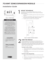
4.1 Mounting the Enclosure
The metal enclosure for the XR150INT/XR550INT Series panels must be mounted in a secure, dry place to
protect the panel from damage due to tampering or the elements. It is not necessary to remove the panel
PCB when installing the enclosure. Figure 2 shows the mounting hole locations for the Model 350INT/350AINT
Enclosures. Figure 3 shows the Model 352PINT panel cabinet and 352S shelf cabinet for multiple batteries.
The 350AINT Attack Resistant enclosure is factory shipped with one knockout on the top left of the
enclosure. As needed, additional knockouts or antenna exits may be added at the time of installation. See
Figure 2 for the positions on the enclosure that can be added. Each additional knockout must be lled with
conduit.
Enclosure Mounting Holes
3-Hole
Pattern for
Accessory
Modules
Tamper Switch
for 350A Attack
Resistant
Enclosure
Dual 1 3/4" and 1 3/8" Conduit Knockouts
Battery Shelf holds up to three 7 Ah Batteries
XR550INT Panel
1
AC
2
AC
3
B+
4
B-
5
BELL
6
GND
7
RED
8
YEL
9
GRN
10
BLK
11
SMK
12
GND
13
Z1
14
GND
15
Z2
16
Z3
17
GND
18
G4
19
Z5
20
GND
21
Z6
22
Z7
23
GND
24
Z8
25
Z9+
26
Z9-
27
Z10+
28
Z10-
PROG
RED BLK
J8
LX500
RED BLK
LX600
RED BLK
J14 J9 J15
LX700
RED BLK
LX800
RED BLK
J15
LX900
RED BLK
XMIT
XBUS
RCV
LX
XMIT RCV
700
600
XMIT RCV
XBUS
J13
Output 2
XMIT RCV
500
PROG
XMIT RCV
J8
PROG
K7
OVC
OUTPUTS
LEV
J2
OUT2OUT1
Output 1
K6
LOAD
J16
J7
RESET
J16 EXP
CELL
MODULE
J24
ETHERNET
J1
BATT S TAR T
PWR
50 VA 75 VA
J12
PHONE LINE
J3
BT1
3V
BR2325
* 350A Optional Knockout
*
**
*
*
J6
K
893A
or 277
3
4
5
6
Figure 2: XR550 International Series panel in Model 350 or 350A Enclosure

XR150INT/XR550INT Series Installation Guide Digital Monitoring Products
7
INSTALLATION
100 VA
Transformer
Mounting for one (1)
Zone Expansion Module.
Battery Shelf
Mounting
Plate
XR550INT Panel
J6
K
Tamper
Switch for
352
Enclosure
Tamper
Switch for
352
Enclosure
Tamper
Switch for
352
Enclosure
Tamper
Switch for
352
Enclosure
Figure 3: XR550 International Series in Model 352XINT Enclosure and Separate 352S Enclosure with
Shelves
4.2 Mounting Keypads and Zone Expansion Modules
DMP LCD keypads have removable covers that allow you to easily mount the keypad to a wall or other at
surface using the screw holes on each corner of the base. Before mounting the base, connect the keypad
wire harness leads to the keypad cable from the panel and to any device wiring run to that location. Then
attach the harness to the pin connector on the PC board, mount the base, and install the keypad cover
making sure all of the keys extend through their respective holes.
For mounting keypads on solid walls, or for applications where conduit is required, use the Model 695 1-1/2”
deep or the Model 696 1/2” deep backboxes.
The DMP 716 module is contained in a molded plastic housing with a removable cover. The base provides you
with mounting holes for installing the unit to a wall, switch plate, or other surface.
The DMP 712-8INT module may be mounted inside the panel enclosure using the 3-hole pattern and plastic
standos.
The DMP 714-8INT, and 714-16INT modules are contained in a DMP Model 340 enclosure.

Digital Monitoring Products XR150INT/XR550INT Series Installation Guide
8
INSTALLATION
4.3 Connecting LX-Bus™, AX-Bus™ and Keypad Bus Devices
Connections for LX-Bus/AX-Bus and Keypads are provided through the PROG, LX500, LX600, LX700, LX800,
and LX900 4-pin headers and the keypad bus. Several factors determine the DMP LX-Bus/AX-Bus and keypad
bus performance characteristics: the wire length and gauge used, the number of devices connected, and
the voltage at each device. When planning an LX-Bus/AX-Bus and keypad bus installation, keep in mind the
following information:
1. DMP recommends using 18 or 22-gauge unshielded wire for all LX-Bus/AX-Bus and keypad circuits.
Do not use twisted pair or shielded wire for LX-Bus/AX-Bus and keypad bus data circuits.
2. On keypad bus circuits, to maintain auxiliary power integrity when using 22-gauge wire do not
exceed 500 feet. When using 18-gauge wire do not exceed 1,000 feet. To increase the wire length or
to add devices, install an additional power supply that is listed for Fire Protective Signaling, power
limited, and regulated (12VDC nominal) with battery backup.
Note: Each panel allows a specic number of supervised keypads. Add additional keypads in the
unsupervised mode. Refer to the Keypad Bus section for the specic number of supervised keypads
allowed.
3. Maximum distance for any one bus circuit (length of wire) is 2,500 feet regardless of the wire gauge.
This distance can be in the form of one long wire run or multiple branches with all wiring totaling no
more than 2,500 feet. As wire distance from the panel increases, DC voltage on the wire decreases.
Maximum number of LX-Bus/AX-Bus devices on the rst 2,500 foot circuit is 40 devices.
4. Maximum voltage drop between the panel (or auxiliary power supply) and any device is 2.0VDC. If
the voltage at any device is less than the required level, add an auxiliary power supply at the end of
the circuit. When voltage is too low, the devices cannot operate properly.
For additional information refer to the LX-Bus/AX-Bus/Keypad Bus Wiring Application Note (LT-2031).
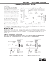
4.4 Wireless Keypad Association
Program from any Keypad Address
You can program the panel from any 32-character wireless keypad or hardwired keypad connected to the
panel’s keypad data bus.
Program from any Wireless Keypad
To enable association operation on a Wireless Graphics Touchscreen keypad (Model 9862INT), access the
Options menu through the carousel menu. While in the Options display, press the Installer Options icon.
Enter the code 3577 (INST) and press CMD. Press KPD RF to start the RF survey communication. The keypad
displays its wireless serial number and RF SURVEY.
To enable wireless keypad association
operation, reset the panel three times
allowing the keypad bus transmit light to
begin ashing between each reset.
For 60 seconds the panel listens for
wireless keypads that are in RF Survey
mode and have not been programmed
or associated into another panel. When
the keypad associates with the panel
the keypad logo LED turns from Red to
Green.
Wireless keypads are assigned to the rst
open device position in Device Setup
automatically based upon the order in
which they are detected.
Transmit/Receive LEDs
Figure 4: XR550 International Series Panel Showing
Reset and Transmit/Receive

XR150INT/XR550INT Series Installation Guide Digital Monitoring Products
9
INSTALLATION
Primary Power Supply
5.1 AC Terminals 1 and 2
Connect the transformer wires to terminals 1 and 2 on the panel. Use no more than 70 ft. of 16 gauge or 40
ft. of 18 gauge wire between the transformer and the panel.
Always ground the panel before applying power to any devices: The XR150INT/XR550INT Series
panels must be properly grounded before connecting any devices or applying power to the panel. Proper
grounding protects against Electrostatic Discharge (ESD) that can damage system components. See the
Earth ground section.
5.2 50VA-75VA 3-Pin Header for Transformer Types
Place the jumper on the right two pins labeled 75VA for a Maximum 3 Amp (Bell+Aux+Smoke+XBUS+LX500-
LX900) when using the Model 324INT 100 VA wire-in transformer.
Secondary Power Supply
6.1 Battery Terminals 3 and 4
Connect the black battery lead to the
negative battery terminal. The negative
terminal connects to the enclosure ground
internally through the XR150INT/XR550INT
Series panels circuit board. Connect the
red battery lead to the battery positive
terminal. Observe polarity when connecting
the battery.
You can add a second battery in parallel
using the DMP Model 318 Dual Battery
Harness.
DMP requires each battery be separated
by a PTC in the battery harness wiring to
protect each battery from a reversal or
short within the circuit. See Figure 5.
Use sealed lead-acid batteries only: Use the DMP Model 364 (12 VDC 1.3Ah), Model 365 (12 VDC 9 Ah),
Model 366 (12 VDC 18 Ah), Model 368 (12 VDC 5.0 Ah), or Model 369 (12 VDC 7 Ah) sealed lead-acid
rechargeable battery. Batteries supplied by DMP have been tested to ensure proper charging with DMP
products.
GEL CELL BATTERIES CANNOT BE USED WITH THE XR150INT/XR550INT SERIES PANEL.
6.2 Earth Ground (GND)
When powering up the panel, terminal 4 can be connected to earth ground (if available) using 14 gauge or
larger wire. Additional options are cold water pipe or ground rod. Gas pipes or sprinkler pipes should not be
used. Do NOT CONNECT TO AN ELECTRICAL GROUND OR SERVER RACK. A ground connection is not required to
provide normal system operation.
6.3 Battery Only Restart
When powering up the XR150/XR550 International Series panel without AC power, briey short across the
battery start pads to pull in the battery cuto relay. The leads need a momentary short only. Once the relay
has pulled in, the battery voltage holds it in that condition. If the XR150/XR550 International Series panel is
powered up with an AC transformer, the battery cuto relay is pulled in automatically. For more information
refer to Figure 1.
6.4 Battery Replacement Period
DMP recommends replacing the battery every 3 to 5 years under normal use.
6.5 Discharge/Recharge
The XR150INT/XR550INT Series panels battery charging circuit oat charges at 13.8 VDC at a maximum
current of 1.5 Amps using a 100 VA transformer. Listed below are the various battery voltage level conditions:
Battery Trouble: Below 11.2VDC
Battery Cuto: Below 10.2VDC
Battery Restored: Above 12.6VDC
AC
1234
+BAC –B
Battery
Start
318 Battery
Harness
Panel Red and
Black Battery Cables
Red
Black
Battery
Battery
Battery
318 Battery
Harness
Red
Black
56
BELLGND
To AC
14 AWG to
Earth Ground
XR550
Panel
PTC
PTC
To Bell
Circuit
Figure 5: Wiring Multiple Batteries

Digital Monitoring Products XR150INT/XR550INT Series Installation Guide
10
INSTALLATION
6.6 Battery Supervision
The XR150INT/XR550INT Series panels tests the battery when AC power is present. The test is done every
three minutes and lasts for ve seconds. During the test, the panel places a load on the battery; if the
battery voltage falls below 11.2 VDC a low battery is detected. If AC power is not present, a low battery is
detected any time the battery voltage falls below 11.2 VDC.
If a low battery is detected with AC power present, the test repeats every two minutes until the battery
charges above 12.6 VDC indicating the battery has restored voltage. If a weak battery is replaced with a
fully charged battery, the restored battery will not be detected until the next two minute test is completed.
6.7 Battery Cuto
The panel disconnects the battery any time the battery voltage drops below 10.2 VDC. This prevents battery
deep discharge damage.
6.8 Power Requirements
During AC power failure, the XR150INT/XR550INT Series panel and all connected auxiliary devices draw
their power from the battery. All devices must be taken into consideration when calculating the battery
standby capacity. The following table lists the XR150INT/XR550INT Series panel power requirements. You
must add the additional current draw of keypads, zone expansion modules, smoke detector output, and any
other auxiliary devices used in the system for the total current required. The total is then multiplied by the
number of standby hours required to calculate the total ampere-hours required.
Standby Battery Power Calculations Standby Current Alarm Current
XR150INT/XR550INT Series Control Panel
Relay Outputs 1-2 (ON)
Switch Grounds 3-6 (ON)
Active Zones 1-8
Active Zones 9-10
2-Wire Smoke Detectors
Panel Bell Output
Qty 1
Qty _______
Qty _______
Qty _______
Qty _______
Qty _______
x 174mA
30mA
5mA
1.6mA
4mA
0.1mA
174 mA
______
______
______
______
______
Qty 1
Qty _______
Qty _______
Qty _______
Qty _______
Qty _______
x 217mA
30mA
5mA
2mA*
30mA
0.1mA
1500mA
217 mA
______
______
______
______
______
______mA
263LTE-INT-A Cellular Communicator Qty _______ x 20mA ______ Qty _______ x 20mA ______
1100XINT Wireless Receiver Qty _______ x 25mA ______ Qty _______ x 35mA ______
860 Relay Output Module (one relay active)
All four relays active
Qty _______ x 34mA
138mA
______
______
Qty _______ x 34mA
138mA
______
______
7060-WINT Thinline Keypad Qty _______ x 72mA ______ Qty _______ x 87mA ______
7063-WINT Thinline Keypad Qty _______ x 85mA ______ Qty _______ x 100mA ______
7070-WINT Thinline Keypad
Active Zones (EOL Installed)
Qty _______ x 72mA
1.6mA
______
______
Qty _______
Qty _______
x
x
87mA
2mA*
______
______
7073-WINT Thinline Keypad
Active Zones (EOL Installed)
Qty _______ x 85mA
1.6mA
______
______
Qty _______
Qty _______
x
x
100mA*
2mA
______
______
7872-WINT Graphic Touchscreen Keypad
Active Zones (EOL Installed)
Qty _______ x 130mA
1.6mA
______
______
Qty _______
Qty _______
x
x
188mA
2mA*
______
______
7873-WINT Graphic Touchscreen Keypad
Active Zones (EOL Installed)
Qty _______ x 143mA
1.6mA
______
______
Qty _______
Qty _______
x
x
243mA
2mA*
______
______
734INT Access Control Module
Active Zones (EOL Installed)
Annunciator (ON)
Qty _______
Qty _______
x
x
40mA
1.6mA
______
______
Qty _______
Qty _______
Qty _______
x
x
x
60mA
2mA*
20mA
______
______
______
Copy Sub-Totals to next page Sub-Total Standby ______mA Sub-Total Alarm ______mA
*Based on 10% of active zones in alarm.

XR150INT/XR550INT Series Installation Guide Digital Monitoring Products
11
INSTALLATION
Standby Battery Power Calculations Standby Current Alarm Current
738Z+INT Z-Wave Interface Module Qty _______ x 40mA ______ Qty _______ x 40mA ______
710INT Bus Splitter/Repeater Module Qty _______ x 32mA ______ Qty _______ x 32mA ______
712-8INT Zone Expansion Module
Active Zones (EOL Installed)
Qty _______
Qty _______
x
x
17mA
1.6mA
______
______
Qty _______
Qty _______
x
x
17mA
2mA*
______
______
714-8INT, 714-16INT Zone Expansion Module
Active Zones (EOL Installed)
Qty _______
Qty _______
x
x
20mA
1.6mA
______
______
Qty _______
Qty _______
x
x
20mA
2mA*
______
______
716INT Output Expansion Module
Active Form C Relays
Qty _______
Qty _______
x
x
13mA
1.6mA
______
______
Qty _______
Qty _______
x
x
13mA
2mA*
______
______
Aux. Powered Devices on Terminals 7 and 11
Other than Keypads and LX-Bus Modules
______mA ______mA
This page only Sub-Total Standby ______mA Sub-Total Alarm ______mA
Sub-Totals from previous page Sub-Total Standby ______mA Sub-Total Alarm ______mA
*Based on 10% of active zones in alarm Total Standby ______mA Total Alarm ______mA
Total Standby______mA x number of Standby Hours needed
Total Alarm
______ =
______mA
Total
_______mA-hours
+_______mA-hours
_______mA-hours
X .001
= _______Amp-hrs Required
Refer to section 6.9 for standby battery selection.

Digital Monitoring Products XR150INT/XR550INT Series Installation Guide
12
INSTALLATION
6.9 Standby Battery Selection
To choose the type and number of batteries needed for 24, 60, or 72 hours of standby power based on the
Amp Hours Required calculation from section 6.8 XR150INT/XR550INT Series Power Requirements, perform
the following:
1. Select the desired standby hours required from the table below: 24, 60, or 72 hours
2. Select the desired battery size: Model 368 (12 VDC 5.0 Ah), Model 369 (12 VDC 7 Ah),
Model 365 (12 VDC 9 Ah), Model 366 (12 VDC 18 Ah).
3. Select a Max. Ah Available number that is just greater than the number calculated in Amp Hours
Required.
4. Install the number of batteries shown in the corresponding No. of Batteries required column.
Example: If the Amp Hours Required calculation equals 22 Ah for 24 hours of standby time and 5.0 Ah batteries
are desired, install six (6) Model 368 (12 VDC, 5.0 Ah) batteries.
Note: The Model 324INT Wire-in 100 VA Transformer may be used with any of the battery choices listed
below.
For listed installations, batteries can be installed in a DMP Model 349, 350 or 352S enclosure and all wiring
shall run through conduit. The enclosure shall be installed to the left of the XR150INT/XR550INT Series panel
enclosure to ensure Battery and AC wire separation.
24 hours of standby power
5.0 Ah Batteries 7 Ah Batteries 7.7 Ah Batteries 9 Ah Batteries 18 Ah Batteries
Max. Ah
Available
No. of
Batteries
Max. Ah
Available
No. of
Batteries
Max. Ah
Available
No. of
Batteries
Max. Ah
Available
No. of
Batteries
Max. Ah
Available
No. of
Batteries
8 2 6 1 6 1 8 1 16 1
12 3 12 2 13 2 16 2 32 2
16 4 18 3 20 3 24 3 48 3
20 5 24 4 27 4 32 4
24 6 31 5 34 5 40 5
28 7 37 6 41 6
32 8 43 7
36 9 Note: 48 hours is the typical battery recharge time for any of the Number of
Batteries shown in this section.
40 10
60 hours of standby power
7 Ah Batteries 7.7 Ah Batteries 9 Ah Batteries 18 Ah Batteries
Max. Ah
Available
No. of
Batteries
Max. Ah
Available
No. of
Batteries
Max. Ah
Available
No. of
Batteries
Max. Ah
Available
No. of
Batteries
13 2 14 2 17 2 17 1
20 3 22 3 26 3 34 2
27 4 29 4 34 4 52 3
33 5 37 5 43 5 69 4
40 6 44 6 52 6
47 7 52 7 61 7 Note: 48 hours is the typical battery
recharge time for any of the Number of
Batteries shown in this section.
54 8 59 8 69 8
60 9 67 9
67 10
72 hours of standby power
9 Ah Batteries 18 Ah Batteries
Max. Ah
Available
No. of
Batteries
Max. Ah
Available
No. of
Batteries
16 2 16 1
25 3 33 2
33 4 50 3
42 5 67 4
50 6
59 7 Note: 72 hours is the typical battery recharge time required for any of the Number of
Batteries shown in this section.
67 8
Note: If the Amp Hours Required calculation is greater than any Max. Ah Available number shown on a table,
then add power supply(s) to power some system devices allowing the Amp Hours Required calculation to be
reduced. See the 710 Bus Splitter/Repeater Installation Guide (LT-0310).

XR150INT/XR550INT Series Installation Guide Digital Monitoring Products
13
INSTALLATION
Bell Output
7.1 Terminals 5 and 6
Terminal 5 supplies positive 12 VDC to power alarm bells or horns. This output can be steady, pulsed, or
temporal depending upon the Bell Action specied in Bell Options. Terminal 6 is the ground reference for the
bell circuit. This supervised output detects 1k Ohms or less as normal. The indicating appliance can supply
this resistance. If using a horn or siren, a 1k Ohm 1/2 W EOL resistor (provided) should be added across the
bell circuit to provide supervision. See the Notication Appliance section for a list of approved notication
appliances and the Wiring Diagrams for connections.
Keypad Bus
8.1 Description
XR150INT/XR550INT Series panel terminals 7, 8, 9, and 10 are for the keypad bus. You can connect up
to 16 supervised keypads to the XR550INT Series panel and 8 supervised keypads to the XR150INT Series
panel as well as multiple unsupervised keypads. In addition to DMP LCD keypads, you can also connect any
combination of zone expansion modules to the data bus up to a total of 16 devices.
Note: Do not use shielded wire for LX-Bus/Keypad Bus circuits.
8.2 Terminal 7 - RED
This terminal supplies positive 12 VDC Regulated to power DMP LCD keypads and zone expansion modules.
Terminal 7 also supplies power for any auxiliary device. The ground reference for terminal 7 is terminal 10.
The output current is shared with the smoke power output on terminal 11 and Zones 9 and 10. Current draw
for all connected devices must not exceed the panel maximum current rating. See Power Supply in the
Compliance section for maximum current in a re listed application.
8.3 Terminal 8 - YELLOW
Terminal 8 receives data from keypads and zone expansion modules. It cannot be used for any other
purpose.
8.4 Terminal 9 - GREEN
Terminal 9 transmits data to keypads and zone expansion modules. It cannot be used for any other purpose.
8.5 Terminal 10 - BLACK
Terminal 10 is the ground reference for DMP LCD keypads, zone expansion modules, and all auxiliary devices
being powered by terminal 7.
8.6 Programming (PROG) Connection
The 4-pin PROG header is provided to connect a keypad when using a DMP Model 330 Programming Cable.
This provides a quick and easy connection for panel programming.
You may also use the PROG header to connect Keypad Bus devices. This is
an alternative to connecting keypad bus devices to terminals 7, 8, 9, and
10.
Note: The programming keypad must be set to address 1.
8.7 Keypad Bus LEDs
The two LEDs, located above the PROG header, indicate data transmission
and receipt. The left LED ashes green to indicate the panel is
transmitting keypad bus data. The right LED ashes yellow to indicate the
panel is receiving keypad bus data. See Figure 6.
8.8 OVC LED(s)
The Overcurrent LED (OVC) lights Red when the devices connected to the Keypad Bus and LX-Bus(es) draw
more current than the panel is rated for. The LED(s) turn a steady Red when lit. When the OVC LED(s) light
Red, the appropriate LX-Bus(es) and Keypad bus are shut down.
• The OVC LED located to the left of the 893A connector indicates overcurrent for the Keypad Bus
(Terminals 7-10 and PROG header), XBUS, and LX500-LX700.
• The OVC LED to the right of the CELL MODULE connector indicates overcurrent for LX800-LX900.
PROG
LX500
LX600
LX700
LX800
LX900
10
BLK
11
SMK
12
GND
13
Z1
14
GND
15
Z2
16
Z3
17
GND
18
Z4
19
Z5
20
GND
22
Z7
21
Z6
RED BLK
RED BLK RED BLK RED BLK RED
J17
BLK
XMIT RCV
RED BLK
XMIT RCV
J8
J14 J9
XMIT
RCV
XMIT
RCV
XMIT
RCV
XMIT
RCV
PROG
500 600 700
Figure 6: PROG Header and LEDs

Digital Monitoring Products XR150INT/XR550INT Series Installation Guide
14
INSTALLATION
Smoke and Glassbreak Detector Output
9.1 Terminals 11 and 12
Terminal 11 supplies positive 12 VDC Regulated to power 4-wire smoke detectors and other powered devices.
This output can be turned o by the user for 5 seconds using the Sensor Reset User Menu option to allow
latched devices to reset. Terminal 12 is the ground reference for terminal 11.
9.2 Current Rating
The Output current from terminal 11 is shared with terminals 7, 25, 27, and LX500-LX900.
The total current draw of all devices powered from the panel must be included with terminal 11
calculations and must not exceed the maximum output rating.
Protection Zones
10.1 Terminals 13–24
Zones 1 to 8 (terminals 13 to 24) on the XR150INT/XR550INT Series panel are all grounded burglary zones.
For programming purposes, the zone numbers are 1 through 8. Listed below are terminal 13 to 24 connection
functions.
Terminal Function Terminal Function
13 Zone 1 voltage sensing 19 Zone 5 voltage sensing
14 Ground for Zones 1 and 2 20 Ground for Zones 5 and 6
15 Zone 2 voltage sensing 21 Zone 6 voltage sensing
16 Zone 3 voltage sensing 22 Zone 7 voltage sensing
17 Ground for Zones 3 and 4 23 Ground for Zones 7 and 8
18 Zone 4 voltage sensing 24 Zone 8 voltage sensing
The voltage sensing terminal measures the voltage across a 1k Ohm End-of-Line resistor to ground. Use DMP
Model 311 1k Ohm resistors. Dry contact sensing devices can be used in series (normally-closed) or in parallel
(normally-open) with any of the burglary protection zones.
10.2 Operational Parameters
Each burglary protection zone detects four conditions: tamper, open, normal, and short.
The parameters for each are listed below:
Condition Resistance on zone Voltage on zone terminal
Tamper over 2.43 k Ohms > 2.9 VDC
Open 1.43 k Ohms to 2.43k
Ohms
2 to 2.9 VDC
Normal .215 k Ohms to 1.43 k
Ohms
1.2 to 2.0 VDC
Short under 215 Ohms under 1.2 VDC
1K Ohm
1K Ohm
R2
R1
Dual 1K Ohm
Normally Closed
1K Ohm
1K Ohm
R2
R1
1K Ohm
1K Ohm
R2
R1
Dual 1K Ohm
Normally Open
Dual 1K Ohm
Combination Normally
Open and Normally Closed
Door Door Door
Tamper
Figure 7: Protection Zone Contact Wiring

XR150INT/XR550INT Series Installation Guide Digital Monitoring Products
15
INSTALLATION
10.3 Zone Response Time
A condition must be present on a zone for 400 milliseconds before it is detected by the XR150INT/XR550INT
Series panel. Ensure detection devices used on the protec tion zones are rated for use with this delay. Zones
1-10 can also be programmed for a fast response delay of 160 milliseconds.
10.4 Keyswitch Arming Zone
Using a keyswitch on an Arming type zone allows you to arm and disarm selected areas without having to
enter a user code.
Powered Zones for 2-Wire Smoke Detectors
11.1 Terminals 25–26 and 27–28
Panel terminals 25 through 28 provide two resettable Class B, Style A, 2-wire powered zones. For
programming purposes the zone numbers are 9 and 10.
Note: The maximum wire length for either zone 9 or zone 10 is 3000 feet using 18 AWG or 1000 feet using
22 AWG. The maximum voltage is 13.8 VDC and the maximum normal standby current is 1.25 mA DC. The
maximum line impedance is 100 Ohms. The maximum short circuit current is 56mA.
When using zone expansion modules, use Model 309 EOL resistors. The compatibility identier for the zones
is A.
Note: Do not mix detectors from dierent manufacturers on the same zone.
Caution: Performing a Sensor Reset momentarily drops power to the devices on Zones 9 and 10. The panel
views these zones (9 and 10) as “Open” while the power is absent.
Dry Contact Relay Outputs
12.1 Description
The XR150INT/XR550INT Series panel provides two programmable auxiliary SPDT relays when equipped
with two DMP Model 305 relays in sockets OUTPUT 1 and OUTPUT 2 and a Model 431 Output Harness on the
OUT1-OUT2 6-pin Header. Each relay provides one SPDT set of contacts that can be operated by any of the
functions listed below:
1) Activation by zone condition: Steady, Pulsing, Momentary, and Follow
2) Activation by 24-hour 7-day schedule: One on and one o time a day for each relay
3) Manual activation from the DMP LCD keypad menu
4) Communication failure 12) Ready
5) Armed area annunciation 13) Armed
6) Fire Alarm, Fire Trouble or Supervisory 14) Disarmed
7) Ambush Alarm 15) Burglary
8) Exit and Entry timers 16) Phone Trouble
9) System Ready 17) Device Fail
10) Late to Close 18) Sensor Reset
11) Panic Alarm 19) Closing Wait
Refer to the XR150INT/XR550INT Series Programming Guide (LT-1232INT) for specic information.
12.2 Contact Rating
The Model 305 relay contacts are rated for 1 Amp at 30VDC (allows .35 power factor). Connect auxiliary
power to the Relay Output 1 common terminal by installing the gray harness wire to terminal 7. Current
draw for all connected devices must not exceed the panel maximum current rating.

Digital Monitoring Products XR150INT/XR550INT Series Installation Guide
16
INSTALLATION
12.3 Model 431 Output Harness Wiring
The relay contacts are accessible by installing the DMP 431 Output Harness on the 6-pin header labeled
OUT1-OUT2. OUTPUT 2 uses the top three prongs, and OUTPUT 1 uses the bottom three prongs. The wire
harness and contact locations are shown below:
Contact Color
Output 1 normally closed Violet
Output 1 common Gray
Output 1 normally open Orange
Output 2 normally closed Violet with white stripe
Output 2 common White with gray stripe
Output 2 normally open Orange with white stripe
The relay contacts must be connected to devices located within the same room as the XR150INT/XR550INT
Series panel.
Annunciator Outputs
13.1 Description
The four programmable annunciator outputs can be programmed to indicate the activity of the panel zones
or conditions occurring on the system. Annunciator outputs do not provide a voltage but instead switch-
to-ground a voltage from another source. The outputs can respond to any of the conditions listed in the
Description section for Dry Contact Relays. Maximum voltage is 30VDC @ 50mA.
13.2 Model 300 Harness Wiring
Access the open collector outputs by installing DMP 300 Harness on the OUTPUTS 4-pin header. The output
locations are shown below. For listed applications, devices connected to the outputs must be located within
the same room as the panel.
Output Color Wire Output Color Wire
3Red 1 5 Green 3
4 Yellow 2 6 Black 4
13.3 Model 860INT Relay Module
Connect a Model 860INT Relay Module to the OUTPUTS header on the XR150INT/XR550INT Series panel to
provide relays for outputs 3-6.
Use these relays for electrical isolation between the alarm panel and other systems or for switching voltage
to control various functions. Power is supplied to the relay coils from a single wire connected to the
panel auxiliary power terminal 7. The module includes one relay and provides three additional sockets for
expansion of up to four relays. Mount the module inside the panel enclosure using the 3-hole pattern and
plastic standos. Refer to the 860INT Module Install Sheet (LT-0484INT) as needed.
Relay Contact Rating: 1 Amp at 30 VDC (allows .35 power factor)
Wireless Bus Expansion
14.1 Description
The Wireless Bus (XBUS) header provides connection for the 1100XINT Wireless Receiver. The XBUS provides
up to 500 wireless zones numbered 500-999. Refer to the 1100XINT Wireless Receiver Install Guide
(LT-1822INT) for complete information.
• XR550INT provides up to 500 zones
• XR150INT provides up to 100 zones
14.2 Wireless Bus LEDs
The two LEDs, located above the XBus header, indicate data transmission and receipt. The left LED ashes
green to indicate the panel is transmitting data. The right LED ashes yellow to indicate the panel is
receiving data.
/