Page is loading ...

TracVision® UHD7
Installation Guide

TracVision UHD7 Installation Guide
1
KVH, TracVision, and the unique light-colored dome with dark contrasting baseplate (Reg. No. 2,864,752) are registered
trademarks of KVH Industries, Inc. All other trademarks are property of their respective companies. The information in this
document is subject to change without notice. No company shall be liable for errors contained herein.
© 2021 KVH Industries, Inc., All rights reserved. 54-1308 Rev. B | 72-0872
This guide explains how to install the TracVision UHD7 satellite TV antenna system on a vessel.
Operation instructions are provided in the Help.
Installation Steps
Who Should Install the System?
To ensure a safe and effective installation, KVH recommends that a KVH-authorized marine
technician install the TracVision antenna. KVH-authorized technicians have the tools and
electronics expertise necessary to install the system. To find a technician near you, visit
www.kvh.com/wheretogetservice.
Technical Support
If you need technical assistance, please contact KVH Technical Support:
1. Inspect Parts and Get Tools .................... 3
2. Plan the Antenna Installation................. 4
3. Plan the TV-Hub Installation.................. 5
4. Prepare the Antenna Site......................... 6
5. Prepare the RF Cables.............................. 7
6. Wire the Antenna ..................................... 9
7. Remove the Shipping Restraints............ 8
8. Mount the Antenna................................ 10
9. Mount the TV-Hub................................. 11
10. Wire the TV-Hub.................................... 12
11. Wire the Receivers.................................. 13
12. Connect a NMEA Device ...................... 18
13. Connect Power........................................ 19
14. Turn On the System ............................... 21
15. Access the Web Interface....................... 22
16. Connect to an Onboard Network......... 23
17. Secure the Wi-Fi Connection ................ 24
18. Set Up the System................................... 25
19. Configure SWM Receivers/DVRs ....... 27
20. Run a Check Switch Test....................... 28
21. Educate the Customer............................ 29
North/South America, Australasia
Phone: +1 401 847-3327
Email: support@kvh.com
(Mon.-Fri., 9 am-6 pm; Sat., 9 am-2 pm ET, -5 GMT)
Europe, Middle East, Africa, Asia-Pacific
Phone: +45 45 160 180
Email: support@kvh.com
(Mon.-Thu., 8 am-4:30 pm; Fri., 8 am-2 pm, +1 GMT)

2
This icon indicates a danger, warning, or caution notice. Be sure to read these carefully to avoid
injury.
WARNING
Risk of Electric Shock
To avoid electric shock, do not open the TV-Hub chassis enclosure. There are no user-serviceable parts
inside.
WARNING
Risk of Electric Shock
If any component of the TracVision system becomes damaged and/or no longer functions normally,
disconnect it from vessel power, secure it from unintended operation, and contact KVH Technical
Support (see “Technical Support” on page 1). All repairs or modifications must be performed by a
trained, KVH-certified technician. If you are a KVH-certified technician, you still must contact KVH
Technical Support prior to conducting any repairs or modifications to the equipment.
WARNING
Risk of Explosion
Do not operate the TV-Hub (or any other electrical device) in an environment where flammable gases,
vapors, or dusts are present. In addition, do not operate the TV-Hub in an environment with a
temperature outside its 5º F to 131º F (-15º C to 55º C) temperature range.
WARNING
Risk of Electric Shock
Failure to ground the TracVision system properly to ship’s ground will cause an unsafe floating
ground condition, risking potentially lethal electric shock. See “Connect Power” on page 19 for details
on the proper grounding of the equipment.
Important Safety Information

3
Before you begin, follow these steps to ensure
you have everything needed to complete the
installation.
a. Unpack the box and ensure it contains
everything shown on the Kitpack Contents
List. Save the packaging for future use.
b. Carefully examine all of the supplied parts to
ensure nothing was damaged in shipment.
c. Gather the tools and materials listed below,
to complete the installation.
• Flat-head and Phillips-head screwdrivers
• Electric drill and 1/2" (13 mm) and 1/8"
(3 mm) drill bits
• 3" (80 mm) hole saw
• 7/16" open-end torque wrench set to
20 in.-lbs (2.25 N-m)
• 7/16" open-end torque wrench set to
15 in.-lbs (1.7 N-m)
• Socket wrenches
• Light hammer and center punch
• Adhesive tape and scriber or pencil
• RG-6 or RG-11 RF coax cables, with “F”
connectors, and termination tools (see
page 7)
• Silicone sealant or equivalent
• Additional SWM splitters, as required
• Satellite TV receiver(s)/DVR(s) for your
desired service (see Figure 2)
• Multimeter
• Wi-Fi-enabled laptop PC Apple® iOS or
Android™ smartphone/tablet with the
KVH TracVision TV-series/UHD7/RV1/
A9 app, and the latest software and
satellite library downloaded from the KVH
Partner Portal (www.kvh.com/partners)
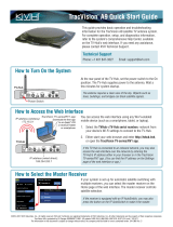
Always lift the antenna by the baseplate or
the hoist holes in the internal frame, and
never by the radome or any other portion of
the internal antenna assembly (see Figure 1).
Antenna
TV-Hub
Radome
Baseplate
Figure 1: TracVision UHD7 System Components
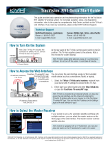
Figure 2: KVH-Validated Receivers
* List is subject to change. For information on
connecting different receiver models, contact KVH
Technical Support.
DIRECTV* DISH Network*
H20
H21
H22
H23
H24
H25
H44
HR21
HR21 Pro
HR22
HR23
HR24
HR34
HR44
HR54
311
211
211k
211z
Wally
Bell TV*
6100
6131
6400
Inspect Parts and Get Tools
1
IMPORTANT!

4
Before you begin, consider the following antenna
installation guidelines.
• Minimize blockage. The antenna requires a
clear view of the sky to receive satellite TV
(see Figure 3). The fewer obstructions, the
better the system will perform.
• Consider the distance between your antenna
and any radar. KVH requires that you do not
mount the antenna on the same level as the
radar because the radar’s energy may
damage the LNB. Most radar transmitters
emit RF energy within an elevation range of
-15º to +15º (see Figure 4). Therefore, mount
the antenna outside of this elevation range
and at least 3 ft (1 m) away from the radar.
• Make sure the mounting surface is wide
enough to accommodate the antenna’s base
(see Figure 5). Also make sure it is flat, level
(within ±1°), strong enough to support the
antenna’s weight (52 lbs, 23.6 kg), and rigid
enough to prevent antenna vibration.
• Select a location that is as close as possible to
the intersection of the vessel’s fore-and-aft
centerline and midships.
• Be sure to mount the antenna near enough to
the TV-Hub to allow you to connect the 100 ft
(30 m) coax cables between them, while still
maintaining sufficient service loops in the
cables.
NOTE: If you need to use a longer cable, use a RG-11
(75 ) cable that does not exceed 200 ft (60 m) in
length (see “Prepare the RF Cables” on page 7).
Be sure to follow the guidelines below.
Damage caused by an improper installation is
not covered under KVH warranty.
IMPORTANT!
Figure 3: Blockage from Obstruction
Mast Vessel Platform
Blocked!
12.5° to 80°
Look Angle
Antenna
Figure 4: Distance from Radar
+15°
-15°
3 ft (1 m)
Minimum
Potential RF
Interference Antenna
Radar
Antenna
Antenna
Never place the antenna in the beam path of
the radar, regardless of distance. The radar’s
energy may damage the antenna or impair its
performance.
IMPORTANT! Figure 5: Antenna Dimensions
27.28"
(69.3 cm)
12"
(30.5 cm)
6"
(15.2 cm)
Ø0.50"
(1.3 cm)
Ø26.2"
(66.6 cm)
FWD
Plan the Antenna Installation
2

5
Consider the following TV-Hub installation
guidelines.
• Select a mounting location in a dry, well-
ventilated area belowdecks away from any
heat sources or salt spray.
• Do not install the TV-Hub in an area
surrounded by metal or near any electrical
devices that emit RF noise.
• The TV-Hub can be mounted horizontally or
vertically on a flat surface (see Figure 6 and
Figure 7).
• Be sure the TV-Hub LED lights will be visible
to the user.
• Select a location that will provide adequate
clearance for the TV-Hub dimensions (see
Figure 6 and Figure 7).
• Leave enough room behind the rear panel
(horizontal mount) or below the rear panel
(vertical mount) to accommodate connecting
the cables and making service loops within
the proper bend radius for strain-relief.
• If you plan to use the TV-Hub’s Wi-Fi
connections, ensure the TV-Hub mounting
location provides adequate Wi-Fi reception.
• If you plan to connect the TV-Hub to the
vessel’s onboard local area network (LAN),
choose a location near an available Ethernet
port.
NOTE: A template showing the exact locations of the
TV-Hub mounting holes and the dimensions between
them is provided in the Welcome Kit. Installation
details are provided in “Mount the TV-Hub” on
page 11.
1.73"
(4.4 cm)
9.34"
(23.7 cm)
7.90"
(20.0 cm)
LED Lights
3.23"
(8.2 cm)
Figure 6: TV-Hub Dimensions - Horizontal Orientation
Top View
9.34"
(23.7 cm)
11.13"
(28.3 cm)
10.52"
(26.7 cm)
7.90"
(20.0 cm)
LED Lights
Figure 7: TV-Hub Dimensions - Vertical Orientation
Plan the TV-Hub Installation
3

6
Once you have identified a suitable antenna
mounting site, according to the guidelines
provided on page 4, follow these steps to drill the
mounting holes and cable access hole to prepare
the site for installation.
a. Unfold the antenna mounting template
(supplied in the Customer Welcome Kit) and
place it onto the mounting surface. Make sure
the “FWD” (forward) arrow points toward
the bow and is parallel to the vessel’s
centerline (see Figure 8). Tape in place.
NOTE: You don’t need to mount the antenna exactly
on the vessel’s centerline (the closer, the better), but
the antenna’s forward arrow must be parallel to it.
b. Using a light hammer and center punch,
mark the locations for the four mounting
holes and cable access hole on the mounting
surface in the locations indicated on the
template.
c. Drill a 1/2" (13 mm) hole at the four
mounting hole locations you marked in
Step b. Later, you will insert four 3/8"-16
bolts through these holes to secure the
antenna to the mounting surface.
d. Cut out the 3" (80 mm) cable access hole in
the location you marked in Step b. Smooth
the edges of the hole to protect the cables.
Later, you will route the RF cables through
this hole and into the vessel.
e. Clean and dry the antenna mounting surface.
f. Peel off the paper backing from the supplied
foam seal to expose the adhesive. Then press
the foam seal down firmly onto the mounting
surface, ensuring the hole in the foam seal
aligns with the cable access hole in the
mounting surface (see Figure 8).
NOTE: Apply the foam seal to the vessel mounting
surface, not to the antenna’s baseplate. You will have
difficulty connecting the cables to the antenna if the
foam seal is attached to the baseplate.
12"
(305 mm)
Ø1/2" (Ø13 mm)
Mounting Hole (x4)
12"
(305 mm)
Ø3" (Ø 80 mm)
Cable Access Hole
FWD
Align Foam Seal
with Cable
Access Hole
Figure 8: Antenna Mounting Holes Layout
Prepare the Antenna Site
4

7
Determine the necessary type of RF cables and
connectors you need for any RF cables that are
required (see Figure 9 and Figure 14 on page 9).
Then follow the guidelines below to prepare the
cables. Two 100 ft (30 m) RG-6 cables are
provided in the kitpack. Additional and longer
cables are also available.
Note: LMR-400-75 is a suitable substitute.
Up to 100 ft (30 m) Cable Run
Cable RG-6
(KVH part no. 32-0417-0100)
Connector Belden SNS1P6
(KVH part no. 23-0170)
Tools Augat IT1000
(KVH part no. 19-0242)
Strip
Lengths
Up to 200 ft (60 m) Cable Run
Cable RG-11
(KVH part no. 32-1272-0200)
Connector PPC Belden-brand EX Series 11
(PPC part no. EX11N716PLUS)
(KVH part no. 23-0917)
Tools PPC Belden-brand VT-200, Klein
Tools 63050, Belden CST596711
or Cablematic® DDT-596/11,
Klein 63050 (KVH part no. 72-
0493)
Strip
Lengths
0.25" (6.35 mm)
0.5" (12.7 mm)
0.04" (1.02 mm) di
a.
0.312" (7.93 mm)
0.562" (14.3 mm)
0.064" (1.63 mm) dia.
Figure 9: RF Cable Requirements
• Do not reuse old RF cables from a
previous antenna installation. The RF1
cable between the TV-Hub and the
antenna carries not only satellite signal,
but power and data as well. Therefore, the
integrity and reliability of this cable is
critically important.
• RF cables must be rated for 75not 50
• Use of any cables not specified in Figure 9
will void the warranty.
• Low-quality, poorly terminated, or
improperly installed RF cables are the
most common cause of system problems.
Terminate all RF cables with high-quality
“F” connectors using the proper
stripping/crimping tools, exactly to the
manufacturer’s specifications.
• When determining cable lengths, be sure
to account for an adequate service loop,
approximately 8" (20 cm) at both ends of
each cable.
IMPORTANT!
Prepare the RF Cables
5

8
Follow these steps to remove the shipping
restraints from inside the antenna.
a. Using a #2 Phillips screwdriver, remove the
six #10-32 Phillips screws securing the
radome to the baseplate (see Figure 10).
Carefully lift the radome straight up until
clear of the antenna assembly and set it aside
in a safe place.
If you keep the radome topside, secure it with
a lanyard to prevent it from falling
overboard. Also, do not place the radome on
a hot steel deck – the heat may warp the
radome.
b. Using a 9/16" nut driver or wrench, remove
the four bolts, two brackets, and two washers
securing the antenna to the shipping pallet
(see Figure 11).
Figure 10: Removing the Radome
#10-32 Screw (x6)
Radome
Baseplate
Figure 11: Shipping Restraints
Bracket
and Bolt (x2)
Bolt and
Washer (x2)
Figure 12: Antenna Hoisting Holes
Hoisting Hole (x2)
If necessary, use the two 0.5" (12.5 mm)
holes in the antenna frame (see Figure 12) to
hoist the antenna to its mounting location.
DO NOT use any other structure inside the
antenna — doing so might damage the
antenna.
IMPORTANT!
Once you have removed the restraints, keep
the antenna level as much as possible and
handle the antenna very carefully. Prevent
the internal antenna assembly from rotating
freely within the baseplate to avoid damaging
the limit switch.
IMPORTANT!
Remove the Shipping Restraints
6

9
Determine the number of tuners the system will
need to support and the number of RF cables you
will need for your installation (refer to the tables
in Figure 13 and Figure 14). Then follow the steps
below to connect the cables to the antenna.
a. Clearly label all RF cables at both ends of
each cable to match the connector. This will
make it easier to identify them later.
b. Route the RF cables belowdecks through the
3" (80 mm) cable access hole. Leave an
adequate service loop, approximately 8"
(20 cm) of slack, in the cables for easy
serviceability.
c. Remove the rubber caps from the RF
connectors on the bottom of the antenna that
you will use (see Figure 15). Leave the caps
on all unused connectors.
d. Clean and dry the connectors on the RF cables
and the antenna with a solvent or alcohol.
e. Fill half of the inner body of the RF1 cable’s
connector with the supplied silicone grease.
f. Connect and SLOWLY hand-tighten the RF1
cable to the “RF1” connector on the bottom of
the antenna, allowing the grease to diffuse
and settle into the entire space within the
connector.
g. Make sure the RF cable is hand-tightened all
the way into the connector. Then tighten it
with a 7/16" torque wrench to 20 in.-lbs.
h. Wipe off any excess grease from the outside
of the connector.
i. Repeat steps e-h to connect additional RF
cables to the antenna’s RF2-RF5 connectors,
as necessary.
j. Seal the RF cable connections with silicone
sealant or equivalent and weatherproof the
cable access hole as required.
CAUTION
Observe the safe handling instructions in the
Material Safety Data Sheet (MSDS) provided
with the silicone grease.
Figure 13: Number of Tuners Per SWM Device
SWM Device No. Tuner(s)
SWM Receiver 1
SWM DVR 2
Genie (HR34/HR44) 5
Genie (HR54) 7
Genie Client 0
Figure 14: Number of RF Coax Cables to Connect to Antenna
* Two SWM expansion kits are available for installations that
require 27 to 52 tuners (KVH part no. 72-0897) or 53 to 104
tuners (72-0898).
SWM Tuners No. Cables Antenna Connectors
13 or fewer 2 RF1 and RF2
14 or more 3 RF1, RF2, and RF3
27 or more* 5 RF1, RF2, RF3, RF4,
and RF5
Figure 15: Connectors on Bottom of Antenna
To Power
Inserter
Required if the
system will support
14 or more tuners
tuners
To T V- Hub Required if the
system will support
27 or more tuners
(need expansion kit)
Wire the Antenna
7

10
Follow these steps to mount the antenna.
a. Place the antenna over the holes drilled in the
mounting surface. Ensure the forward arrow
points toward the bow and is parallel to the
vessel’s centerline (see Figure 16).
b. Apply a thin layer of the supplied anti-seize
lubricant to the threads of the four 3/8"-16
mounting bolts (see Figure 17).
c. At each of the four baseplate mounting holes,
place a 3/8" flat washer on a 3/8"-16 bolt and
insert the bolt into the hole (with preinstalled
3/8" shoulder washer) from above (see
Figure 17). To enable proper grounding, ensure
the preinstalled shoulder washers are in place
and were not dislodged during handling.
d. Secure each mounting bolt to the mounting
surface using a 3/8" shoulder washer, a
3/8" flat washer, and a 3/8"-16 lock nut from
below. Tighten all four bolts until the four
rubber feet on the baseplate are bottomed
against the mounting surface and the foam seal
is fully compressed. KVH recommends that
you tighten the bolts to between 12 and
16 ft-lbs (16.2 and 21.7 N-m) of torque.
e. Using cutting pliers, cut and remove the two
tie-wraps equipped with paper tags (see
Figure 18).
f. Rotate the antenna through its full range of
motion, to ensure there is no interference, and
inspect the inside of the antenna to make sure
you have not left any tools or debris inside.
g. Reinstall the radome onto the antenna. Secure
it in place with the screws you removed on
page 8. Hide and protect the screws with
plastic screw caps (supplied in kit).
CAUTION
Be sure to observe the safe handling
instructions in the Material Safety Data Sheet
(MSDS) provided with the anti-seize lubricant.
Figure 16: Forward Arrow in Antenna Baseplate
You will need to rotate the antenna assembly
by hand to see all four mounting holes. Rotate
it slowly to avoid damaging the limit switch.
IMPORTANT!
3/8"-16 Bolt (x4)
3/8" Flat Washer (x4)
Rubber Foot (x4)
Mounting Surface
3/8" Flat Washer (x4)
3/8"-16 Lock Nut (x4)
Antenna Baseplate
3/8" Shoulder Washer (x4)
3/8" Shoulder Washer (x4)
Preinstalled
IMPORTANT: Apply
anti-seize to threads
Figure 17: Mounting the Antenna (Side View)
Figure 18: Antenna Restraints
Tie-wrap Tie-wrap
Mount the Antenna
8

11
Follow these steps to install the TV-Hub inside
the vessel.
a. Tape the mounting template in the location
selected for the TV-Hub. Punch holes at each
of the two keyhole locations and at the
mounting tab location.
b. Remove the template.
c. Drill a 1/8" (3 mm) hole at the three hole
locations you marked in Step a.
d. Install a #8 Phillips thread-forming screw
partway into one of the keyhole holes leaving
a small gap for hooking the TV-Hub onto it.
Use the thickness (2.5 mm) of the M10 washer
(supplied in kit) as a gauge for the size gap to
leave.
e. Repeat step d for the other keyhole.
f. Peel off the backing on the adhesive-backed
washer (supplied in kit) and place it over the
mounting tab hole (see Figure 19).
g. Align the wide part of the TV-Hub’s
keyholes, as shown in Figure 20, over the
screws, then slide downwards to secure the
screws into the narrow part of the keyholes.
h. Press the rear mounting tab of the TV-Hub
onto the adhesive washer and install the third
#8 Phillips thread-forming screw in the
mounting tab hole.
Before continuing, locate the serial number on
the bottom of the TV-Hub and record it on the
Installation Checklist (supplied in the
Welcome Kit) for future reference.
IMPORTANT!
7.93"
(20.1 cm)
3.17"
(8.1 cm)
4.86"
(12.3 cm)
Front of TV-Hub
Keyhole
2 x Ø 0.13"
(Ø 0.3 cm)
Mounting Tab
Ø 0.13"
(Ø 0.3 cm)
Figure 19: TV-Hub Mounting Template
Keyhole (x2)
Mounting Tab
Figure 20: TV-Hub Keyholes and Mounting Tab
Mount the TV-Hub
9

12
Follow these steps to connect the antenna cables
to the belowdecks equipment.
a. Connect a grounding block in-line with each
RF cable from the antenna (see Figure 21 and
“Grounding Requirements” on page 19).
b. Connect the RF1 cable from the antenna to
the “Antenna” jack on the TV-Hub (see
Figure 21).
c. Hand-tighten the RF cable until it is all the
way into the “Antenna” jack. Then tighten it
with a 7/16" torque wrench set to 15 in.-lbs.
d. Connect the RF2 cable from the antenna to
the “Power to SWM” connector on the SWM
power inserter (see Figure 21).
e. Using fasteners appropriate for the mounting
surface, secure the power inserter to the
mounting surface.
NOTE: Do not connect the SWM power inserter’s
AC power cable to vessel power at this time. Power
will be connected in “Connect Power” on page 19.
Figure 21: TV-Hub Antenna Connection
WI-FI
BA
LEN=1
NMEA 0183
NMEA 2000
POWER
DC IN
MAX CURRENT 10A
10-30V
RESET
ETHERNET
RECEIVER
GROUND
ANTENNA
FUSE
POWER
TO SWM
AC Power
SWM Power
Inserter
Antenna
Deck
TV-Hub
Antenna
Grounding
Block
RF1 RF2
Do not connect anything other than the
antenna’s RF1 cable to the “Antenna” jack.
The TV-Hub supplies voltage that will
damage other devices, such as multiswitches,
receivers, DVRs, etc.
IMPORTANT!
Wire the TV-Hub
10

13
The steps for connecting the customer’s receiver(s)
to the TracVision system and setting them up
depends upon the customer’s satellite TV service.
Follow the steps in the applicable section below to
wire the receivers. Then connect the receiver(s) to
the customer’s television(s).
DIRECTV (SWM) Wiring . . . . . . . page 14
DISH Network/Bell TV Wiring. . page 17
NOTE: The DISH Network/Bell TV section includes
steps to connect most non-Wally DISH receivers. To
connect Wally receivers, refer to “Using Wally
Receivers” on page 30.
Figure 22: Receiver/DVR Wiring
WI-FI
BA
LEN=1
NMEA 0183
NMEA 2000
POWER
DC IN
MAX CURRENT 10A
10-30V
RESET
ETHERNET
RECEIVER
GROUND
ANTENNA
FUSE
DISH Network and
Bell TV Receivers
TV-Hub
Antenna
POWER
TO SWM
AC Power
SWM Power
Inserter
DIRECTV U.S.
SWM Receivers
Note: The system does not support
DIRECTV non-SWM receivers.
Receiver
Antenna
Deck
RF1 RF2
If you have any DISH/Bell receiver(s) other
than a Wally, during setup, you will need to
temporarily connect the receiver(s), one at a
time, directly to the “Receiver” port on the
TV-Hub and run a Check Switch test. Refer to
“Run a Check Switch Test” on page 28 or to
the Help for more details.
IMPORTANT!
Wire the Receivers
11

14
DIRECTV – SWM Wiring
Follow these steps to connect DIRECTV receivers
to the TracVision system.
Connecting 1 SWM Receiver/DVR
Connect an RF cable from the “Signal to IRD”
connector on the SWM power inserter to the
“Satellite In” jack on the receiver (see Figure 23).
Connecting Up to 8 SWM Receivers (13 Tuners Max)
a. Connect an RF cable from the “Signal to IRD”
connector on the SWM power inserter to the
“SWM” input on an 8-way SWM splitter (see
Figure 24).
b. Connect the SWM splitter’s outputs to the
“Satellite In” jack on the receivers/DVRs (or
“Network” jack when connecting a Genie
client). You can connect up to 8 SWM devices
that add up to 13 or fewer tuners. Refer to
Figure 24 to determine the tuners consumed by
each type of device.
NOTE: HR34 and HR44 Genies both reserve 5 tuners.
The HR54 Genie reserves 7 tuners.
c. Terminate any unused outputs on the splitter
with 75terminators and tighten with a
7/16" torque wrench set to 20 in.-lbs.
Figure 23: Wiring 1 DIRECTV Receiver
WI-FI
BA
LEN=1
NMEA 0183
NMEA 2000
POWER
DC IN
MAX CURRENT 10A
10-30V
RESET
ETHERNET
RECEIVER
GROUND
ANTENNA
FUSE
AC Power
SWM Receive
r
Deck
TV-Hub
Grounding
Block
Satellite In
RF1
Antenna
Antenna
AC Power
SWM Power
Inserter
SIGNAL
TO IRD
POWER
TO SWM
RF2
Figure 24: Wiring Up to 8 DIRECTV Receivers
AC Power
SWM Receiver/DVR
Satellite In
SWM Splitter
AC Power
SWM Power
Inserter
SIGNAL
TO IRD
POWER
TO SWM
Note: Connect any combination of receivers, DVRs, and
Genie clients that add up to 13 or fewer tuners on the
RF2 cable. Only 3 Genie clients can be active at one time.
Terminate
unused
outputs
Supports up to 13 tuners:
Each SWM receiver = 1 tuner
Each SWM DVR = 2 tuners
Each Genie DVR = 5 or 7 tuners
Each Genie client = 0 tuners
Genie DVR
Genie Client
Network
R
AUDIO OUT
L
PrPbY
VIDEO OUT S-VIDEO OUT
DIGITAL
AUDIO OUT
ETHERNET
SATELLITE IN 1
IR RECEIVE SATA HDMI PHONE JACK
POWER INPUT
USB
COMPONENT VIDEO OUT
AC Power
AC Power
Satellite In
Continued Wire the Receivers
11

15
Connecting 9 -13 SWM Receivers (13 Tuners Max)
a. Connect an RF cable from the “Signal to IRD”
connector on the SWM power inserter to the
“SWM” input on a 2-way SWM splitter (see
Figure 25).
b. Connect the 2-way SWM splitter’s outputs to
the “SWM” inputs on two 8-way SWM splitters.
c. Connect the 8-way SWM splitter’s outputs to
the “Satellite In” jacks on the receivers/DVRs
(or “Network” jack when connecting a Genie
client). Connect any combination of SWM
devices that add up to 13 or fewer tuners. Refer
to Figure 25 to determine the tuners consumed
by each type of device.
NOTE: HR34 and HR44 both reserve 5 tuners. The
HR54 reserves 7 tuners.
d. Terminate any unused outputs on the splitters
with 75terminators and tighten with a
7/16" torque wrench set to 20 in.-lbs.
When wiring the receivers, be sure to keep the
number of splits to no more than two per path.
IMPORTANT!
Figure 25: Wiring Up to 13 DIRECTV Receivers
WI-FI
BA
LEN=1
NMEA 0183
NMEA 2000
POWER
DC IN
MAX CURRENT 10A
10-30V
RESET
ETHERNET
RECEIVER
GROUND
ANTENNA
FUSE
Terminate
unused
outputs
SWM 8-way
Splitter
SWM 8-way
Splitter
SWM 2-way
Splitter
Maximum of
two splitters
per path
Deck
TV-Hub
Supports up to 13 tuners:
Each SWM receiver = 1 tuner
Each SWM DVR = 2 tuners
Each Genie DVR = 5 or 7 tuners
Each Genie client = 0 tuners
AC Power
SWM Receiver/DVR
Satellite In
Note: Connect any combination of receivers, DVRs, and
Genie clients that add up to 13 or fewer tuners on the
RF2 cable. Only 3 Genie clients can be active at one time.
Genie DVR
Genie Client
Network
R
AUDIO OUT
L
PrPbY
VIDEO OUT S-VIDEO OUT
DIGITAL
AUDIO OUT
ETHERNET
SATELLITE IN 1
IR RECEIVE SATA HDMI PHONE JACK
POWER INPUT
USB
COMPONENT VIDEO OUT
AC Power
AC Power
Satellite In
Antenna
AC Power
SWM Power
Inserter
SIGNAL
TO IRD
POWER
TO SWM
Antenna
RF2
Grounding
Block
RF1
Antenna
Continued Wire the Receivers
11

16
Connecting 14-26 SWM Receivers (26 Tuners Max)
a. Connect up to 13 receivers to the antenna’s RF2
cable, as explained in “Connecting 9 -13 SWM
Receivers (13 Tuners Max)” on page 15.
NOTE: Only use DIRECTV-approved SWM splitters.
Additional 2-way (KVH part no. 19-1016), 4-way
(19-1017), and 8-way (19-0618) SWM splitters are
available.
b. Connect the RF3 cable to any combination of
2-, 4-, and/or 8-way SWM splitters, as
necessary. Do not exceed two splitters per path.
c. Connect the SWM splitter’s outputs to the
“Satellite In” jacks on the receivers/DVRs (or
“Network” jack when connecting a Genie
client). You can connect any combination of
SWM devices that add up to 13 or fewer tuners
on RF2 and up to 13 or fewer tuners on RF3
(26 total). Refer to Figure 26 to determine the
tuners consumed by each type of device.
d. Terminate any unused outputs on the splitters
with 75terminators and tighten with a
7/16" torque wrench set to 20 in.-lbs.
When wiring the receivers, be sure to keep the
number of splits to no more than two per path.
IMPORTANT!
Figure 26: Wiring Up to 26 DIRECTV Receivers
WI-FI
BA
LEN=1
NMEA 0183
NMEA 2000
POWER
DC IN
MAX CURRENT 10A
10-30V
RESET
ETHERNET
RECEIVER
GROUND
ANTENNA
FUSE
SWM 2-way
Splitter
Maximum of
two splitters
per path
Deck
AC Power
SWM
Power
Inserter
TV-Hub
RF1 RF3
Terminate
unused
outputs
SWM 8-way
Splitter
SWM 8-way
Splitter
AC Power
SWM Receiver/DVR
Satellite In
Note: Connect any combination of receivers, DVRs, and Genie
clients that add up to 13 or fewer tuners on each RF cable
(RF2 and RF3). Only 3 Genie clients can be active at one time.
Genie DVR
Genie Client
Network
R
AUDIO OUT
L
PrPbY
VIDEO OUT S-VIDEO OUT
DIGITAL
AUDIO OUT
ETHERNET
SATELLITE IN 1
IR RECEIVE SATA HDMI PHONE JACK
POWER INPUT
USB
COMPONENT VIDEO OUT
AC Power
AC Power
Satellite In
Antenna
RF2
up to 13 tuners (26 total):
Each SWM receiver = 1 tuner
Each SWM DVR = 2 tuners
Each Genie DVR = 5 or 7 tuners
Each Genie client = 0 tuners
RF2 and RF3 each support
Antenna
Grounding
Block
POWER
TO SWM
SIGNAL
TO IRD
Connect SWM 2-,
4-, or 8-way splitters
to RF3, as necessary
Continued Wire the Receivers
11

17
DISH Network and Bell TV Wiring
Follow these steps to connect most DISH Network
(non-Wally) or Bell TV receivers to the TracVision
system. (To connect Wally receivers, refer to “Using
Wally Receivers” on page 30.)
Connecting 1 Receiver
Connect an RF cable from the “Receiver” jack on
the TV-Hub to the “Satellite In” jack on the
receiver (see Figure 27).
Connecting 2 Receivers
a. Connect an RF cable from the “Receiver” jack
on the TV-Hub to the “Satellite In” jack on the
receiver.
b. Connect the “Primary” jack on the DC block
splitter to the “Satellite In” jack on the first
receiver.
c. Connect the “Secondary” jack on the splitter to
the “Satellite In” jack on the second receiver
(see Figure 28).
Connecting 3 or More Receivers
a. Connect an RF cable from the TV-Hub to the
DC block splitter and connect the DC block
splitter to the first receiver, as explained in
“Connecting 2 Receivers”.
b. Connect the “Secondary” jack on the splitter to
the “18V” port on a multiswitch (see
Figure 29). KVH offers a 4-output passive
multiswitch (KVH part no. 72-0676) and an
8-output active multiswitch (KVH part no.
72-0310).
c. Connect the multiswitch outputs to the
“Satellite In” jacks on the additional receivers.
Receivers must be DISH
Pro-compatible. Look for the
DISH Pro logo on the box.
IMPORTANT!
You must connect the SWM power inserter to
the antenna’s RF2 cable for all DISH/Bell
configurations. The SWM power inserter
supplies power to the antenna’s LNB.
IMPORTANT!
Figure 27: Wiring 1 DISH/Bell Receiver
WI-FI
BA
LEN=1
NMEA 0183
NMEA 2000
POWER
DC IN
MAX CURRENT 10A
10-30V
RESET
ETHERNET
RECEIVER
GROUND
ANTENNA
FUSE
DIRECTV U.S.
SWM Receivers
Deck
TV-Hub
Grounding
Block
RF1
Antenna
Antenna
AC Power
SWM
Power
Inserter
POWER
TO SWM
RF2
Receiver
AC Power
Satellite In
Receiver
Figure 28: Wiring 2 DISH/Bell Receivers
WI-FI
BA
LEN=1
NMEA 0183
NMEA 2000
POWER
DC IN
MAX CURRENT 10A
10-30V
RESET
ETHERNET
RECEIVER
GROUND
ANTENNA
FUSE
Receiver
AC Power
Satellite In
TV-Hub
Receiver
AC Power
Satellite In
Receiver
DC Block
Splitter
Antenna
Secondary
Primary
Figure 29: Wiring 3+ DISH/Bell Receivers
Receiver
AC Power
Satellite In
Connect up to 4 receivers
Terminate
unused
outputs
13V18V
Multiswitch
18V
WI-FI
BA
LEN=1
DSWM
NMEA 0183
NMEA 2000
POWER
DC IN
MAX CURRENT 10A
10-30V
RESET
ETHERNET
RECEIVER
GROUND
ANTENNA
FUSE
Receiver
AC Power
Satellite In
TV-Hub
Receiver
DC Block
Splitter
Antenna
Secondary Primary
Continued Wire the Receivers
11

18
At the customer’s option, you can connect a
NMEA device to the TV-Hub, allowing the
antenna to use its GNSS heading data to speed up
satellite acquisition. A NMEA device will also
provide position data as a backup to the antenna’s
built-in GPS. The current heading will also be
displayed on the Home page of the web interface.
NOTE: The antenna system can only use and display
true heading. If only magnetic heading is input, the
TV-Hub will use the current location data to convert
magnetic heading to true heading.
Follow these steps to connect a NMEA device to
the TV-Hub, if desired.
NMEA 0183
a. Wire and connect the 2-position terminal strip
connector (supplied in kit) as shown in
Figure 30.
b. Configure the NMEA device to transmit one or
more of the supported NMEA 0183 messages
at 4800 baud (see Figure 31).
c. Make sure the data message(s) includes the
checksum, identifiable by a *xx field at the end
of the data sentence (e.g., $HEHDT,123.4,
T*1F). Do not exceed a 10 Hz input rate.
NMEA 2000
a. Connect the TV-Hub to the vessel‘s
NMEA 2000 CAN network backbone via a “T”
connector, as shown in Figure 30. Be sure to
use a standard drop cable: 5-wire
(4 conductors + shield) twisted pair with
micro-C connectors.
b. Configure the NMEA device to transmit one or
more of the supported NMEA 2000 messages
(see Figure 32).
Later, you will select the NMEA source at the
TracVision Setup Wizard (see “Setup Wizard” on
page 26).
Figure 30: TV-Hub NMEA Connections
WI-FI
BA
LEN=1
NMEA
NMEA 2000
0183
POWER
DC IN
MAX CURRENT 10A
10-30V
RESET
ETHERNET
RECEIVER
GROUND
ANTENNA
TV-Hub
OR
B A
1 2
NMEA 0183 Talke
r
NMEA
0183
NMEA 2000 Talker
CAN Network
Backbone
NMEA
2000
Figure 31: Supported NMEA 0183 Messages
NMEA 0183 $--xxx Description
HDG Heading, Deviation &
Variation
HDM Heading, Magnetic
HDT Heading, True
OSD Own Ship Data
THS True Heading & Status
VHW Water Speed and Heading
RMC GNSS Position Data
Figure 32: Supported NMEA 2000 Messages
PGN Description
127250 Vessel Heading
129029 GNSS Position Data
Connect a NMEA Device
12
Optional

19
Before connecting power, be sure the vessel is
properly grounded in accordance with marine
standards.
Grounding Requirements
Proper grounding of the TracVision system to
ship’s ground is mandatory for electromagnetic
compatibility (EMC) and safety regulatory
compliance. It protects the equipment from
electrostatic discharges (ESD) and prevents
interference with other electronic equipment.
Follow these steps to ground the system.
a. Connect the hoop of the grounding wire
(supplied in kit) to the “Ground” screw on the
rear panel of the TV-Hub. Connect the other
end to ship’s common ground.
b. Connect grounding blocks in-line with all of
the RF cables. Attach a ground wire from
each grounding block to ship’s common
ground. Then mount each grounding block
using the two supplied #6 screws (see
Figure 33).
WARNING
Failure to ground the TracVision system
properly to the vessel’s ground will cause an
unsafe floating ground condition, risking
damage to the antenna and electric shock,
potentially resulting in DEATH. In a
floating ground condition, the difference
between the equipment's chassis ground and
the vessel’s ground can measure well over
100 volts, when it normally should not
exceed 2 volts. Therefore, always measure the
difference in potential between chassis
ground and the vessel’s ground to make
certain there is no dangerous floating ground
condition.
The TV-Hub and any grounding blocks must
be connected to the ship’s common ground to
maintain the same electrical ground potential.
IMPORTANT!
Figure 33: Grounding Block Example
#6 Mounting
Screw (x2)
WI-FI
BA
LEN=1
NMEA 0183
NMEA 2000
POWER
DC IN
MAX CURRENT 10A
10-30V
RESET
ETHERNET
RECEIVER
GROUND
ANTENNA
FUSE
AC Power
SWM Receiver
Deck
AC Power
SWM Power
Inserter
TV-Hub
Grounding Block
RF1 RF2
Ground
Ship’s Common
Ground
Connect Power
13
/