TracVision TV10 Installation guide
- Category
- Networking
- Type
- Installation guide

TracVision® T V10
Installation Guide


TracVision TV10 Installation Guide
1
KVH, TracVision, and the unique light-colored dome with dark contrasting baseplate (Reg. No. 2,864,752) are registered
trademarks of KVH Industries, Inc. All other trademarks are property of their respective companies. The information in this
document is subject to change without notice. No company shall be liable for errors contained herein.
© 2020-2022 KVH Industries, Inc., All rights reserved. 54-1345 Rev. B
This guide explains how to install the TracVision TV10 satellite TV antenna system on a vessel.
Operation instructions are provided in the Quick Start Guide.
Installation Steps
Appendices
Who Should Install the System?
To ensure a safe and effective installation, KVH recommends that a KVH-certified marine
technician install the TracVision antenna. KVH-authorized technicians have the tools and
electronics expertise necessary to install the system. To find a technician near you, visit
www.kvh.com/wheretogetservice.
Technical Support
If you need technical assistance, please contact KVH Technical Support:
1. Inspect Parts and Get Tools .................... 3
2. Plan the Antenna Installation................. 4
3. Plan the TV-Hub Installation.................. 7
4. Prepare the Antenna Site......................... 8
5. Prepare the RF Cables.............................. 9
6. Rig/Hoist the Antenna.......................... 10
7. Wire the Antenna ................................... 11
8. Mount the Antenna................................ 13
9. Mount the TV-Hub................................. 15
10. Wire the Antenna to the TV-Hub......... 16
11. Wire the Receivers.................................. 17
12. Connect a NMEA Device ...................... 25
13. Connect Power........................................ 26
14. Turn On the System ............................... 28
15. Access the Web Interface....................... 29
16. Connect to an Onboard Network......... 30
17. Secure the Wi-Fi Connection ................ 31
18. Set Up the System................................... 32
19. Educate the Customer............................ 35
A. Installing a Circular LNB ....................36
B. Installing an IP AutoSwitch................40
C. Using a DIRECTV Coax Network......44
Europe, Middle East, Africa, Asia-Pacific
Phone: +45 45 160 180
Email: [email protected]
(Mon.-Thu., 8 am-4:30 pm; Fri., 8 am-2 pm, +1 GMT)
North/South America, Australasia
Phone: +1 401 847-3327
Email: [email protected]
(Mon.-Fri., 9 am-6 pm; Sat., 9 am-2 pm ET, -5 GMT)

2
This icon indicates a danger, warning, or caution notice. Be sure to read these carefully to avoid
injury.
WARNING
Risk of Electric Shock
To avoid electric shock, do not open the TV-Hub chassis enclosure. There are no user-serviceable parts
inside.
WARNING
Risk of Electric Shock
If any component of the TracVision system becomes damaged and/or no longer functions normally,
disconnect it from vessel power, secure it from unintended operation, and contact KVH Technical
Support (see “Technical Support” on page 1). All repairs or modifications must be performed by a
trained, KVH-certified technician. If you are a KVH-certified technician, you still must contact KVH
Technical Support prior to conducting any repairs or modifications to the equipment.
WARNING
Risk of Explosion
Do not operate the TV-Hub (or any other electrical device) in an environment where flammable gases,
vapors, or dusts are present. In addition, do not operate the TV-Hub in an environment with a
temperature outside its 5º F to 131º F (-15º C to 55º C) temperature range.v
WARNING
Risk of Electric Shock
Failure to ground the TracVision system properly to ship’s ground will cause an unsafe floating
ground condition, risking potentially lethal electric shock. See “Connect Power” on page 26 for details
on the proper grounding of the equipment.
Important Safety Information

3
Before you begin, follow these steps to ensure
you have everything needed to complete the
installation.
a. Unpack the box and ensure it contains
everything shown on the Kitpack Contents
List. Save the packaging for future use.
b. Carefully examine all of the supplied parts to
ensure nothing was damaged in shipment.
c. Gather the tools and materials listed below.
• Flat-head and Phillips-head screwdrivers
• Electric drill and 1/8" (3 mm) and
5/8" (16 mm) drill bits
•5/32" hex key
• 7/16" open-end torque wrench(es) set to
15 in.-lbs and 20 in.-lbs (2.25 N-m)
• 1/2" open-end wrench
• 3/4" and 7/16" sockets/ratchets
• 3/4" socket/torque ratchet set between
35 and 40 ft-lbs (47 and 54 N-m) of torque
• Light hammer and center punch
• Adhesive tape and scriber or pencil
• RG-11 or RG-6 RF coax cable(s), with “F”
connectors, and termination tools (RG-11
must be used for RF1; see “Prepare the RF
Cables” on page 9)
• Silicone sealant or equivalent
• Satellite TV receiver(s)/DVRs for your
desired service (see Figure 2)
•Multimeter
• Wi-Fi-enabled laptop PC Apple® iOS or
Android™ smartphone or tablet with the
KVH TracVision TV-series app, and the
latest software and satellite library
downloaded from the KVH Partner Portal
(www.kvh.com/partners)
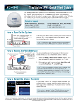
Always lift the antenna by the baseplate and
never by the radome or any portion of the
internal antenna assembly (see Figure 1).
TV-Hub
Radome
Baseplate
Antenna
Figure 1: TracVision TV10 System Components
Figure 2: KVH-Validated Receivers
* List is subject to change. For information on
connecting different receiver models, contact KVH
Technical Support.
Linear
For information on the recommended
receivers for linear service, contact your local
KVH dealer/distributor. Go to
www.kvh.com/wheretogetservice to find a
dealer/distributor near you.
DIRECTV* DISH Network*
H20
H21
H22
H23
H24
H25
HR21, HR21 Pro
HR22
HR23
HR24
311
211
211k
211z
Wally
Bell TV*
6100
6131
6400
Inspect Parts and Get Tools
1
IMPORTANT!

4
Before you begin, consider the following antenna
installation guidelines.
• Minimize blockage. The antenna requires a
clear view of the sky to receive satellite TV
(see Figure 3). The fewer obstructions, the
better the system will perform.
• Consider the distance between your antenna
and any radar. KVH requires that you do not
mount the antenna on the same level as the
radar, because the radar’s energy may
damage the LNB. Most radar transmitters
emit RF energy within an elevation range of
-15º to +15º (see Figure 4). Therefore, mount
the antenna outside of this elevation range
and at least 10 ft (3 m) away from the radar.
Be sure to follow the guidelines below.
Damage caused by an improper installation is
not covered under KVH warranty.
IMPORTANT!
Mast
-20° to 80°
Look Angle
Blocked!
Vessel Platform
Mast
Mast
Figure 3: Blockage from Obstruction
To prevent the antenna from interfering with
any electromagnetic sensitive compasses or
equipment, maintain a minimum distance of
at least 5 ft (1.5 m) between the antenna and
any compasses.
IMPORTANT!
Figure 4: Distance from Radar
+15°
-15°
10 ft (3 m)
Minimum
Potential RF
Interference
Radar
Never place the antenna in the beam path of
the radar, regardless of distance. The radar’s
energy may damage the antenna or impair its
performance.
IMPORTANT!
Plan the Antenna Installation
2

5
• Make sure the mounting surface is wide
enough to accommodate the antenna’s base
(see Figure 5). Also make sure it is flat, level
(within ±1°), strong enough to support the
antenna’s weight (198 lbs (89.8 kg)) and rigid
enough to prevent antenna vibration.
• Be sure to preserve enough free space outside
the access hatch to allow a technician to
remove the hatch and perform maintenance.
• Select a location that is not too high above the
waterline (less than 1/2 the vessel’s length),
and as close as possible to the intersection of
the vessel’s fore-and-aft centerline and
midships.
• Be sure to mount the antenna near enough to
the TV-Hub to allow you to connect the 100 ft
(30 m) coax cable between them, while still
maintaining sufficient slack in the cable.
NOTE: For RF1, you must use an RG-11 cable. If
you need to use a longer cable, use a RG-11 (75
)
cable that does not exceed 200 ft (60 m) in length (see
“Prepare the RF Cables” on page 9).
13V/22KHz
18V/22KHz
Power/Data
13V
18V
57.28"
(145.50 cm)
19.01"
(48.29 cm)
Ø48.80"
(123.00 cm)
Side View
Cable
Connectors
9.74"
(24.74 cm)
Mounting Hole
4x Ø.63" (1.59 cm)
Ø13.78"
(35.00 cm)
Cable Connectors
(cable cover not shown)
Service Hatch (x2)
Bottom View
RF4
RF3RF2
RF1
Figure 5: Antenna Dimensions
Continued Plan the Antenna Installation
2

6
Pedestal Structural Requirements
If a pedestal is going to be used, it must meet the
following minimum requirements. Refer to
Figure 5.
NOTE: If the pedestal exceeds 3.28 ft (1 m), braces
must be placed at 120° intervals. Sizing is based on
Structural Steel Tubing 60,000 psi (415 MPa)
minimum yield.
Pedestal
Height
(A)
3.28 ft
1 m
6.56 ft
2 m
9.84 ft
3 m
Tube OD
(B)
9.0"
230 mm
8.0"
203.2 mm
10"
254 mm
Tube
Wall
Thickness
(C)
0.5"
12.7 mm
0.5"
12.7 mm
0.5"
12.7 mm
Brace
Height
(D)
N/A 5.56 ft
1.7 m
7.34 ft
2.24 m
Brace OD
(E)
N/A 3.0"
76.2 mm
6.0"
152.4 mm
Brace
Thickness
(F)
N/A 0.25"
6.35 mm
0.5"
12.7 mm
Brace
Angle
(G)
N/A 30°25°
E F
Brace
Pedestal
(Side View)
B
C
120°
Pedestal
(Cross-Section)
AD G
Figure 6: Pedestal Dimensions
Continued Plan the Antenna Installation
2

7
Consider the following TV-Hub installation
guidelines.
• Select a mounting location in a dry, well-
ventilated area belowdecks away from any
heat sources or salt spray.
• Do not install the TV-Hub in an area
surrounded by metal or near any electrical
devices that emit RF noise.
• The TV-Hub can be mounted horizontally or
vertically on a flat surface (see Figure 7).
• Be sure the TV-Hub LED lights will be visible
to the user.
• Select a location that will provide adequate
clearance for the TV-Hub dimensions (see
Figure 7).
• Leave enough room behind the rear panel
(horizontal mount) or below the rear panel
(vertical mount) to accommodate connecting
the cables and making service loops within
the proper bend radius.
• If you plan to use the TV-Hub’s Wi-Fi
connections, ensure the TV-Hub mounting
location provides adequate Wi-Fi reception.
• If you plan to connect the TV-Hub to the
vessel’s onboard local area network (LAN),
choose a location near an available Ethernet
port.
NOTE: A template showing the exact locations of the
TV-Hub mounting holes and the dimensions between
them is provided in the Welcome Kit. Installation
details are provided in “Mount the TV-Hub” on
page 15.
1.73"
(4.4 cm)
9.34"
(23.7 cm)
7.90"
(20.0 cm)
LED Lights
3.23"
(8.2 cm)
Horizontal
Orientation
9.34"
(23.7 cm)
11.13"
(28.3 cm)
10.52"
(26.7 cm)
7.90"
(20.0 cm)
Vertical
Orientation
Figure 7: TV-Hub Dimensions
Plan the TV-Hub Installation
3

8
Once you have identified a suitable antenna
mounting site, according to the guidelines
provided in “Plan the Antenna Installation” on
page 4, follow these steps to drill the mounting
holes and cable access hole to prepare the site for
installation.
Drill the Mounting Holes
a. Unfold the antenna mounting template
(supplied in Customer Welcome Kit) and place it
onto the mounting surface. Make sure the
“FWD” (forward) arrow points toward the
bow and is parallel to the vessel’s centerline
(see Figure 8). Tape in place.
NOTE: You don’t need to mount the antenna exactly
on the vessel’s centerline (the closer, the better), but
the antenna’s forward arrow must be parallel to it.
b. Using a light hammer and center punch,
mark the locations of the four mounting holes
on the mounting surface in the locations
indicated on the template.
c. Drill a 5/8" (16 mm) hole at the four
mounting hole locations. Later, you will
insert four 1/2"-13 bolts through these holes
to mount the antenna.
Cut Out the Cable Access Hole, If Needed
If you plan to route the antenna cables
belowdecks through a hole directly underneath
the antenna, follow the steps below.
a. Using the supplied template, mark the
location of the cable access hole in the center
of the mounting hole pattern (see Figure 8).
b. Cut out the 3.75" (95 mm) cable access hole at
the location you marked in step a. Smooth the
edges of the hole to protect the cable(s). Later,
you will route the RF cable(s) through this
hole and into the vessel.
c. Clean and dry the antenna mounting surface.
d. Peel off the paper backing from one of the
supplied foam seals to expose the adhesive.
Then press the foam seal down firmly onto
the mounting surface, ensuring the hole in
the foam seal aligns with the cable access hole
in the mounting surface (see Figure 8).
Figure 8: Antenna Mounting Holes Layout
9.74"
(247.40 mm)
Ø.63" (Ø15.88 mm)
Mounting Hole (x4)
Ø3.75" (Ø95.3 mm)
Cable Access Hole
FWD
Foam Seal
Face Vessel Bow
9.74"
(247.40 mm)
Good Bolt
Pattern
Poor Bolt
Pattern
Prepare the Antenna Site
4

9
Determine the necessary type of RF cable(s) and
connectors you need for any RF cables that are
required in addition to what is supplied in the
antenna kit (see Figure 9 and Figure 10). Then follow
the guidelines and steps below to prepare and route
the cable(s).
Figure 9: Number of RF Coax Cables to Connect to Antenna
* Multiswitch may be required.
LNB Type # of Receivers RF Cables
Stacked Circular or
Sky Mexico
11
2 or more 1*
DIRECTV L.A.
Circular
11
2 or more 2*
Linear Universal
Quad
1, 2, 3, or 4 1, 2, 3, or 4
More than 4 4*
Note: LMR-400-75 is a suitable substitute.
RF2, RF3, or RF4
Up to 100 ft (30 m) Cable Run
Cable RG-6
(KVH part no. 32-0417-0100)
Connector Belden SNS1P6
(KVH part no. 23-0170)
Tools Augat IT1000
(KVH part no. 19-0242)
Strip
Lengths
RF1, RF2, RF3, or RF4
Up to 200 ft (60 m) Cable Run
Cable RG-11 (KVH part no. 32-1272-0200)
Connector PPC Belden-brand EX Series 11
(PPC part no. EX11N716PLUS)
(KVH part no. 23-0917)
Tools PPC Belden-brand VT-200, Klein
Tools 63050, Belden CST596711 or
Cablematic® DDT-596/11, Klein
63050 (KVH part no. 72-0493)
Strip
Lengths
0.25" (6.35 mm)
0.5" (12.7 mm)
0.04" (1.02 mm) dia.
0.312" (7.93 mm)
0.562" (14.3 mm)
0.064" (1.63 mm) dia.
Figure 10: RF Cable Requirements
•You must use an RG-11 cable to connect
RF1.
• Do not reuse old RF cables from a previous
antenna installation. The RF1 cable between
the TV-Hub and the antenna carries not only
satellite signal, but power and data as well.
Therefore, the integrity and reliability of this
cable is critically important.
• RF cables must be rated for 75not 50
• Use of any cables not specified in Figure 10
will void the warranty.
• Low-quality, poorly terminated, or
improperly installed RF cables are the most
common cause of system problems.
Terminate all RF cables with high-quality
“F” connectors using the proper stripping/
crimping tools, exactly to the
manufacturer’s specifications.
• When determining cable lengths, be sure to
account for an adequate service loop,
approximately 14" (36 cm) at both ends of
each cable.
IMPORTANT!
Prepare the RF Cables
5

10
Follow these steps to remove the shipping bolts
securing the antenna to the pallet and safely rig
the antenna for crane hoisting.
a. Using a 7/16" socket/ratchet or nut driver,
unlock the three hex latches securing each of
the antenna’s service hatches (see Figure 11).
Then gently lower the hatches. Now you can
access the four shipping bolts securing the
antenna’s baseplate to the pallet.
b. Using a 3/4" socket/ratchet or wrench,
remove the four 1/2"-13 bolts securing the
antenna to the pallet (see Figure 12). Then set
the bolts aside.
TIP: You will use the new mounting bolts supplied in
the kitpack when mounting the antenna later.
However, you might wish to keep these bolts in case
you need to ship the antenna later.
c. Reinstall both antenna service hatches. Secure
each service hatch using the three hex latches.
d. Secure crane rigging appropriate for lifting
the antenna to each of the antenna’s four lift
brackets (see Figure 13). Be sure the rigging
and crane are suitably rated to safely lift the
198 lbs (89.8 kg) antenna.
e. Carefully hoist the antenna to its mounting
location.
WARNING
Be sure no personnel stand underneath the
antenna at any time while it is suspended in
the air.
The antenna’s radome and baseplate have
painted surfaces. Be sure to take protective
measures to avoid gouging or scratching the
antenna during the rigging operation.
IMPORTANT!
Figure 11: Service Hatch and Hardware
Service
Hatch (x2)
1/4-turn Hex
Latch (x6)
Figure 12: Shipping Bolts (Antenna Bottom View)
1/2"-13
Bolt (x4)
Figure 13: Antenna Crane Rigging (Example)
Lift
Bracket (x4)
Rope to Prevent
Antenna from
Tipping
Rope
Antenna’s
Center of Gravity
Rig/Hoist the Antenna
6

11
Follow these steps to connect the antenna RF
cable(s) to the antenna.
a. Clean and dry the bottom of the antenna
baseplate (see Figure 14).
b. To access the antenna’s connectors, you first
need to detach the cable cover. Loosen the six
#6-32 captive screws securing the cable cover
to the base (see Figure 15). Then set the cable
cover aside in a safe place.
c. If you routed the cables through a hole
directly underneath the antenna (see “Cut
Out the Cable Access Hole, If Needed” on
page 8), peel off the paper backing from the
second supplied foam seal to expose the
adhesive. Align the foam seal so it is centered
on the antenna (see Figure 14). Then press the
foam seal firmly onto the underside of the
antenna.
d. Position the antenna in place over the
mounting holes with the baseplate’s
connectors facing the stern.
e. Clean and dry the connectors on the RF
cable(s) and the antenna (see Figure 16).
f. Clearly label the RF1 cable at both ends. If
you connect two or more RF cables, label both
ends of each cable to match the connector.
This will make it easier to identify them later.
g. Route the RF cable(s) belowdecks through the
cable access hole. Leave an adequate service
loop, approximately 14" (36 cm) of slack, in
the cable(s) for easy serviceability.
h. Fill half of the inner body of the RF1 cable’s
connector with the supplied silicone grease.
i. Connect and SLOWLY hand-tighten the RF1
cable to the “RF1” connector on the side of
the antenna, allowing the grease to diffuse
and settle into the entire space within the
connector (see Figure 16).
CAUTION
Observe the safe handling instructions in the
Material Safety Data Sheet (MSDS) provided
with the silicone grease.
Figure 14: Foam Seal on Base of Antenna
Foam Seal
Antenna Baseplate (Bottom View)
#6-32 Captive
Screw and
Washer (x6) Cable
Cove
r
Figure 15: Cable Cover
Figure 16: Cable Connections
RF4
RF3RF2
RF1
Foam Seals
Baseplate
RF1 RF2 RF3 RF4
Wire the Antenna
7

12
j. Make sure the RF cable is hand-tightened all
the way into the connector. Then tighten it
with a 7/16" torque wrench to 20 in-lbs, or a
7/16" wrench for 1/4 turn.
k. Wipe off any excess grease from the outside
of the connector.
l. Repeat steps h-k to connect any additional RF
cables to the antenna’s RF2, RF3, and RF4
connectors. Later, you will connect RF1 to the
TV-Hub and any other RF cable(s) to a
grounding block and receiver(s).
m. Seal the RF cable connections with silicone
sealant or equivalent.
n. Using a #1 Phillips screwdriver, reinstall the
cable cover to the antenna and secure it in
place with the six #6-32 captive screws and
washers (see Figure 17).
o. Secure the cables near the antenna connectors
to relieve stress (such as the example in
Figure 18). The cable cover is designed for
aesthetics only – it does not provide any
support for the cables and may become
damaged if cables are not properly strain-
relieved.
p. Weatherproof and seal the cable access hole
as required.
Figure 17: Cable Cover/Screws/Washers
13V/22KHz
18V/22KHz
Powe r/D ata
13V
18V
Label
Label
Label
Label
Label
#6-32 Captive Screw
and Washer (x6)
Cable
Cover
Figure 18: Strain-relief/Service Loops Example
Service Loops
Deck
Through-deck
Protection
Gooseneck
To Belowdecks Equipment
Welded or Bolted to
Ship’s Steel Structure
Strain Relief
Continued Wire the Antenna
7

13
Follow these steps to mount the antenna.
a. Using a 7/16" socket/ratchet or nut driver,
unlock the three hex latches securing each of
the antenna’s service hatches (see Figure 11
on page 10). Then gently lower the hatches.
b. Ensure the forward arrow points toward the
bow and is parallel to the vessel’s centerline
(see Figure 19) and the cable connectors face
the stern.
c. Carefully lower the antenna onto the
mounting surface and ensure the mounting
holes (and foam seals, if used) are aligned.
While lowering the antenna, adjust the cables
as necessary to maintain an adequate service
loop, approximately 14" (36 cm) of slack.
d. Apply a thin layer of the supplied anti-seize
lubricant to the threads of the four 1/2"-13
mounting bolts.
e. At each of the four antenna mounting holes,
place a 1/2" flat washer on a 1/2"-13 bolt and
insert the bolt into the hole from above (see
Figure 20).
f. Secure each mounting bolt to the mounting
surface using a 1/2" flat washer and a
1/2"-13 lock nut from below.
g. Tighten the mounting bolts in a cross pattern
until the four rubber feet on the baseplate are
bottomed against the mounting surface. KVH
recommends that you tighten the nuts to
between 35 and 40 ft-lbs (47 and 54 N-m) of
torque.
WARNING
Be sure to observe the safe handling
instructions in the Safety Data Sheet (SDS)
provided with the anti-seize lubricant.
Figure 19: Forward Arrow in Antenna Baseplate
Cable Connectors
(Face Stern)
Forward Arrow
Inside Baseplate
(Point Toward Bow)
Hatch
Hatch
FORWARD
Antenna
(Top View)
If the foam seals are used, do not reposition
the antenna laterally once the antenna’s foam
seal has made contact with the foam seal on
the mounting surface. If you need to
reposition the antenna, lift the antenna first to
avoid damage to the foam seals.
IMPORTANT!
Figure 20: Mounting the Antenna (Side View)
1/2"-13 Bolt (x4)
1/2" Flat
Washer (x4)
Rubber
Foot (x4)
Mounting
Surface 1/2" Flat
Washer (x4)
1/2"-13 Lock
Nut (x4)
Antenna
Baseplate
Isolation
Bushing (x4)
IMPORTANT!
Apply anti-seize
to threads
Foam Seals
Stationary
Plate
(if used) (preinstalled)
Mount the Antenna
8

14
h. Disconnect the crane rigging.
i. Using a 5/32" hex key and 1/2" open-end
wrench, remove the eight screws, flat
washers, and lock nuts securing the four lift
brackets to the antenna (see Figure 21).
Remove the brackets and hardware and set
them aside in a safe place.
TIP: Be sure to save the brackets and bracket hardware
in case you need to relocate the antenna later.
j. Install eight 1/4"-20 screws and washers
(supplied in kit) in place of the longer
mounting bracket screws you removed in the
previous step (see Figure 22).
k. Reinstall both antenna service hatches. Secure
each service hatch using the three hex latches.
Figure 21: Lift Bracket Removal
Lift Bracket
(x4)
1/4"-20 x 1.5"
Screw (x8)
Counter-sunk
Washer (x8)
1/4"-20 Flat
Washer (x8)
1/4"-20 Lock
Nut (x8)
Figure 22: Radome Hardware
1/4"-20 x 7/8"
Screw (x8)
Counter-sunk
Washer (x8)
Continued Mount the Antenna
8

15
Follow these steps to install the TV-Hub inside
the vessel.
a. Tape the mounting template in the location
selected for the TV-Hub. Punch holes at each
of the two keyhole locations and at the
mounting tab location.
b. Remove the template.
c. Drill a 1/8" (3 mm) hole at the three hole
locations you marked in step a.
d. Install a #8 Phillips thread-forming screw
partway into one of the keyhole holes leaving
a small gap for hooking the TV-Hub onto it.
Use the thickness (2.5 mm) of the M10 washer
(supplied in kit) as a gauge for the size gap to
leave.
e. Repeat step d for the other keyhole.
f. Peel off the backing on the adhesive-backed
washer (supplied in kit) and place it over the
mounting tab hole (see Figure 23).
g. Align the wide part of the TV-Hub’s
keyholes, as shown in Figure 24, over the
screws, then slide downwards to secure the
screws into the narrow part of the keyholes.
h. Press the rear mounting tab of the TV-Hub
onto the adhesive washer and install the third
#8 Phillips thread-forming screw in the
mounting tab hole.
Before continuing, locate the serial number on
the bottom of the TV-Hub and record it on the
Installation Checklist (supplied in the
Welcome Kit) for future reference.
IMPORTANT!
7.93"
(20.1 cm)
3.17"
(8.1 cm)
4.86"
(12.3 cm)
Front of TV-Hub
Keyhole
2 x Ø 0.13"
(Ø 0.3 cm)
Mounting Tab
Ø 0.13"
(Ø 0.3 cm)
Figure 23: TV-Hub Mounting Template
Keyhole (x2)
Mounting Tab
Figure 24: TV-Hub Keyholes and Mounting Tab
Mount the TV-Hub
9

16
Follow these steps to connect the antenna to the
TV-Hub.
a. Fill half of the inner body of the RG-11 RF1
cable connector, that you will be connecting
to the TV-Hub, with the supplied silicone
grease.
b. Connect the RG-11 RF1 cable from the
antenna to the “Antenna” jack on the TV-Hub
(see Figure 25).
c. Hand-tighten the RF cable until it is all the
way into the “Antenna” jack. Then tighten it
with a 7/16" torque wrench set to 15 in-lbs, or
a 7/16" wrench 1/8 turn.
d. Wipe off any excess grease from the outside
of the connector.
Do not connect anything other than the
antenna’s RF1 cable to the “Antenna” jack.
The TV-Hub supplies voltage that will
damage other devices, such as multiswitches,
receivers, DVRs, etc.
IMPORTANT!
Figure 25: TV-Hub Antenna Connection
Wi-Fi
LEN=1
10-30V
POWER MAX CURRENT 9.5A
NMEA 0183
BA
ETHERNET DSWM
RECEIVER
GROUND
ANTENNA
RESET
NMEA 2000
DC IN
Deck
Antenna
To antenna only
FUSE
RF1
Wire the Antenna to the TV-Hub
10

17
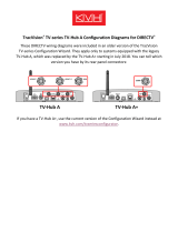
The steps for connecting the customer’s
receiver(s) to the TracVision system and setting
them up depends upon the customer’s satellite
TV service (see Figure 26).
NOTE: KVH’s TracVision Configuration Wizard,
available at www.kvh.com/tvseriesconfigurator,
displays a wiring diagram and parts list for all of the
most common configurations.
Follow the steps in the applicable section below
to wire the receivers. Then connect the receiver(s)
to the customer’s television(s).
Linear. . . . . . . . . . . . . . . . . . . . . . . . page 18
DIRECTV (SWM) . . . . . . . . . . . . . . page 20
DIRECTV Latin America . . . . . . . page 22
DISH Network/Bell TV . . . . . . . . page 23
Sky Mexico . . . . . . . . . . . . . . . . . . . page 24
Figure 26: TV-Hub Receiver Connections
Wi-Fi
LEN=1
10-30V
POWER MAX CURRENT 9.5A
NMEA 0183
BA
FUSE
ETHERNET DSWM
RECEIVER
GROUND
ANTENNA
RESET
NMEA 2000
DC IN
TV-Hub
DISH Network, Bell TV
and Linear Receivers
DIRECTV U.S.
SWM Receivers
Wire the Receivers
11

18
Linear Wiring
Follow these steps to connect linear receivers to
the TracVision system.
NOTE: The linear universal quad LNB is required.
Connecting 1-4 Linear Receivers
a. Connect an RF cable from the “Receiver” jack
on the TV-Hub to the “Satellite In” jack on the
first receiver (see Figure 27). This receiver will
be able to control satellite selection in Automatic
satellite switching mode.
b. When connecting multiple receivers, connect
a grounding block in-line with each RF cable
from the antenna (see Figure 28 and
“Grounding Requirements” on page 26).
c. Connect the other end of the RF1 cable from
the antenna to the “Antenna” jack on the
TV-Hub.
d. Connect any other RF cables from the
antenna (RF2, RF3, and RF4) to the “Satellite
In” jack on each additional receiver (see
Figure 28).
Figure 27: Wiring 1 Linear Receiver
TV-Hub
Wi-Fi
LEN=1
10-30V
POWER MAX CURRENT 9.5A
NMEA 0183
BA
FUSE
ETHERNET DSWM
RECEIVER
GROUND
ANTENNA
RESET
NMEA 2000
DC IN
Receiver
AC Power
Satellite In
Antenna
Receiver
RF1
TV-Hub
Wi-Fi
LEN=1
10-30V
POWER MAX CURRENT 9.5A
NMEA 0183
BA
FUSE
ETHERNET DSWM
RECEIVER
GROUND
ANTENNA
RESET
NMEA 2000
DC IN
Antenna
Receiver
AC Power
Satellite In
Receiver
RF1
Receiver
AC Power
Satellite In
Receiver
AC Power
Satellite In
Receiver
AC Power
Satellite In
RF4RF3RF2
Grounding
Blocks
Figure 28: Wiring 2 to 4 Linear Receivers
To enable any of the additional receivers to
control satellite selection, install an optional IP
AutoSwitch (KVH part no. 72-0634) in-line
with the receiver’s RF input. See Appendix B
on page 40 for details.
IMPORTANT!
Continued Wire the Receivers
11
Page is loading ...
Page is loading ...
Page is loading ...
Page is loading ...
Page is loading ...
Page is loading ...
Page is loading ...
Page is loading ...
Page is loading ...
Page is loading ...
Page is loading ...
Page is loading ...
Page is loading ...
Page is loading ...
Page is loading ...
Page is loading ...
Page is loading ...
Page is loading ...
Page is loading ...
Page is loading ...
Page is loading ...
Page is loading ...
Page is loading ...
Page is loading ...
Page is loading ...
Page is loading ...
Page is loading ...
Page is loading ...
Page is loading ...
Page is loading ...
Page is loading ...
Page is loading ...
Page is loading ...
Page is loading ...
-
 1
1
-
 2
2
-
 3
3
-
 4
4
-
 5
5
-
 6
6
-
 7
7
-
 8
8
-
 9
9
-
 10
10
-
 11
11
-
 12
12
-
 13
13
-
 14
14
-
 15
15
-
 16
16
-
 17
17
-
 18
18
-
 19
19
-
 20
20
-
 21
21
-
 22
22
-
 23
23
-
 24
24
-
 25
25
-
 26
26
-
 27
27
-
 28
28
-
 29
29
-
 30
30
-
 31
31
-
 32
32
-
 33
33
-
 34
34
-
 35
35
-
 36
36
-
 37
37
-
 38
38
-
 39
39
-
 40
40
-
 41
41
-
 42
42
-
 43
43
-
 44
44
-
 45
45
-
 46
46
-
 47
47
-
 48
48
-
 49
49
-
 50
50
-
 51
51
-
 52
52
-
 53
53
-
 54
54


TracVision TV10 Installation guide
- Category
- Networking
- Type
- Installation guide
Ask a question and I''ll find the answer in the document
Finding information in a document is now easier with AI
Related papers
-
 TracVision TV1 Installation guide
-
 TracVision TV5 Installation guide
-
 TracVision RV1 Installation guide
-
 TracVision A9 User guide
-
 TracVision TV8 Installation guide
-
 TracVision A9 Quick start guide
-
 TracVision TV10 User guide
-
 TracVision TV6 Installation guide
-
 TracVision HD7 Installation guide
-
 TracVision RV1 Quick start guide


Other documents
-
KVH Industries TracVision TV10 Installation guide
-
-
-
-
-
-
 KVH TV-Hub A Owner's manual
-
 KVH TracVision M7 Owner's manual
-
-

