Page is loading ...

POWERAMP® • Division of Systems, Inc. • W194 N11481 McCormick Drive • Germantown, WI 53022
800.643.5424 • fax: 262.257.7399 • www.poweramp.com • [email protected]
Printed in U.S.A.
Copyright © 2017
Manual No. 4111-0008
April 2017
June 2017
VS SERIES
Dock Leveler
Owner’s/User’s Manual

Page
Precautions
Recognize Precautionary Information ................................................ 1
General Operational Precautions ........................................................ 1
Operational Precautions ...................................................................... 2
Maintenance Precautions ..................................................................... 4
Precaution Decal’s ................................................................................ 5
Owners/Users Responsibility .............................................................. 6/7
Introduction
General Information .............................................................................. 7
Dock Leveler Stock Specifications ..................................................... 7
Component Identification ..................................................................... 8
Installation
Prepare Pit ............................................................................................. 9
Prepare Dock Leveler .......................................................................... 10
Install Dock Leveler ............................................................................. 11
Install Control Panel and Wiring ........................................................ 14
Put New Leveler Into Service.............................................................. 16
Operation
Theory ................................................................................................... 18
Operating Instructions ........................................................................ 19
Ramp Loading/Unloading Instructions ........................................ 20
End Loading/Unloading Instructions ........................................... 21
Maintenance
Service Dock Leveler .......................................................................... 22
Periodic Maintenance .......................................................................... 23
Adjustments
Adjust PPAC Pressure Relief ............................................................. 26
Adjust Main Pressure Relief ............................................................... 27
Purging Hydraulic System .................................................................. 17
Limit Switch .......................................................................................... 28
Rod Eye Adjustment ............................................................................ 17
Troubleshooting
Troubleshooting ................................................................................... 31
Parts
Misc. Parts ............................................................................................ 34
Frame and Platform ............................................................................. 37
Hydraulic Components ........................................................................ 40
Hydraulic Valve Components ............................................................. 46
Hoist Cylinder Repair Parts ................................................................ 52
Lip Cylinder Repair Parts ................................................................... 53
Power Pack Assembly, Remote ........................................................ 54
Miscellaneous
Customer Information ......................................................................... 57
Warranty ................................................................................................ Back Cover
Table of Contents

1
4111-0008 — April 2017
June 2017
PRECAUTIONS
O
p
e
r
a
t
i
n
g
Z
o
n
e
The use of the word DANGER signifies the
presence of an extreme hazard or unsafe practice
which will most likely result in death or severe
injury.
The use of the word WARNING signifies the
presence of a serious hazard or unsafe practice
which could result in death or serious injury.
The use of the word CAUTION signifies possible
hazard or unsafe practice which could result in
minor or moderate injury.
Recognize Precautionary Information
The Safety-Alert Symbol This is the safety alert
symbol. It is used to alert you to the potential
physical injury hazard. Obey all safety messages
that follow this symbol to avoid possible death or
injury.
Safety - Alert Symbol
The use of the word NOTICE indicates information
considered important, but not hazard-related, to
prevent machine or property damage.
Indicates a type of safety sign, or separate panel
on a safety sign, where safety-related instructions
or procedures as described.
Do not start the equipment until all unauthorized
personnel in the area have been warned and have
moved outside the operating zone.
Remove any tools or foreign objects from the operat-
ing zone before starting.
Keep the operating zone free of obstacles that could
cause a person to trip or fall.
Read and understand the Owner’s/User’s manual and
become thoroughly familiar with the equipment and
its controls before operating the dock leveler.
Never operate a dock leveler while a safety device or
guard is removed or disconnected.
Never remove DANGER, WARNING, or CAUTION
signs or decal’s on the equipment unless replacing
them.
General Operational Precautions

24111-0008 — April 2017
June 2017
PRECAUTIONS
Stay clear of dock leveling device when transport
vehicle is entering or leaving area.
Do not move or use the dock leveling device if
anyone is under or in front of it.
Keep hands and feet clear of pinch points. Avoid
putting any part of your body near moving parts.
Stay clear of dock leveling device when transport
vehicle is entering or leaving area.
Do not move or use the dock leveling device if
anyone is under or in front of it.
Keep hands and feet clear of pinch points. Avoid
putting any part of your body near moving parts.
Chock/restrain all transport vehicles, Never
remove the wheel chocks until loading or
unloading is finished and transport driver has been
given permission to drive away.
Do not use a broken or damage dock leveling
device. Make sure proper service and
maintenance procedures have been performed
before using.
Make sure lip overlaps onto transport vehicle bed
at least 4 in. (102 mm).
Keep a safe distance from both side edges.
Operational Safety PrecautionsOperational Precautions
Learn the safe way to operate this equipment. Read and understand the
manufacturer’s instructions. If you have any questions, ask your supervisor.

3
4111-0008 — April 2017
June 2017
PRECAUTIONS
Do not use dock leveling device if transport
vehicle is too high or too low.
Do not overload the dock leveling device.
Do not operate any equipment while under the
influence of alcohol or drugs.
Do not leave equipment or material unattended on
dock leveling device.
Operational Precautions

44111-0008 — April 2017
June 2017
PRECAUTIONS
1.50"
3.00"
Decal Size: 1.5 x 3
File Name: 1751-0736 Rev A
Arc Flash and
Shock Hazard
PPE [Personal Protection
Equipment] Required
De-energize equipment before
working on or inside. Do not
open cover without appropriate
PPE. Refer to NFPA 70E for
PPE requirements. This panel
may contain more than one
power source.
Hazardous Voltage
Will Result in Death
or Serious Injury
1751-0736 Rev A
Maintenance Precautions
Hydraulic and electrical power must be OFF when
servicing the equipment. For maximum protection,
use an OSHA approved locking device to lock
out all power sources. Only the person servicing
the equipment should have the key to unlock the
device.
ALWAYS disconnect electrical power source and
ground wire before welding on dock leveler.
DO NOT ground welding equipment to any hydraulic
or electrical components of the dock leveler. Always
ground to the dock leveler frame.
ALWAYS stand clear of dock leveler lip when
working in front of the dock leveler.
DO NOT grind or weld if hydraulic fluid or other
flammable liquid is present on the surface to be
ground or welded
DO NOT grind or weld if uncontained hydraulic
fluid or other flammable liquid is present. Stray
sparks can ignite spills or leaks near the work area.
Always clean up the oil leaks and spills before
proceeding with grinding or welding.
Always keep a fire extinguisher of the proper type
nearby when grinding or welding.
A
B
TOLERANCES
(UNLESS OTHERWISE NOTED)
FRACTIONAL: 1/32"
DECIMAL:
.00 = .01"
.000 = .005"
ANGULAR: 1
MATERIAL
DRAWN BY CHECKED BY
DRAWING NO.
DATE
mikemartin 2/4/2015
vs prop
P O W E R A M P
M C G U I R E
D L M
S Y S T E M S, I N C.
L o a d i n g D o c k E q u i p m e n t
This print is the property of Systems, Inc. and represents a proprietary article in which Systems, Inc. retains any and all
patent and other rights, including exclusive rights of use and/or manufacture and/or sale. Possession of this print does
not convey any permission to reproduce, print or manufacture the article or articles shown therein, such permission to be
granted only by written authorization signed by an officer or other authorized agent of Systems, Inc. thereof.
STOCK NO.
FIG.“A”
FIG.“B”
File Name: 1751-0230 Rev E
Decal Size: 3.75 x 6.25
CRUSH HAZARD
DO NOT WORK UNDER OR IN FRONT OF
DOCK LEVELER unless ALL props have been
properly positioned and secured. First position
side maintenance prop(s) and secure with screw
and nut as shown in figure “A” below. Then
position storage prop and secure with prop lock
pin as shown in figure “B” below. Failure to do so
will result in death or serious injury. Refer to
owner’s/user’s manual for proper procedure.
Prop Lock
Pin
Storage
Prop
Stored
Position
Maintenance
Position
Screw and Nut
Maintenance
Prop
1751-0230 Rev E
Always post safety warnings and barricade the
work area at dock level and ground level to prevent
unauthorized use of the unit before maintenance is
complete.

5
4111-0008 — April 2017
June 2017
PRECAUTIONS
Precautionary Decal’s
2
3
4
5
6
1
1
27
8
4
22
5
7
6
13
VS Series
1
9
88
PROUDLY
MADEIN USA
SYSTEMS, INC.
GERMANTOWN, WI
MALVERN, AR
9
.
CRUSH HAZARD
Before doing any maintenance, repair or adjustments on the
dock leveler, first store the leveler in a vertical position with lip
extended, then ensure all maintenance props are in
maintenance positions and properly secured, and then
properly secure the storage prop with the prop lock pin.
DO NOT remove the prop lock pin from the storage prop until
you are sure the hydraulic system is in proper working condition
and all maintenance props are in maintenance positions and
properly secured. After prop lock pin is removed from the
storage prop all maintenance props may be returned to
storage positions. DO NOT stand in front of the dock leveler.
Reach from side of the leveler.
DO NOT force the prop lock pin out of the storage prop. If the
pin does not slide freely, support the leveler securely using other
means and determine the cause of the interference.
Failure to follow these instruction will result in death or serious
injury.
Refer to owner’s/user ’s manual for proper procedure. 1751-0130 Rev D
FIG.“A”
FIG.“B”
CRUSH HAZARD
DO NOT WORK UNDER OR IN FRONT OF DOCK
LEVELER unless ALL props have been properly
positioned and secured. First position side
maintenance prop(s) and secure with screw and
nut as shown in figure “A” below. Then position
storage prop and secure with prop lock pin as
shown in figure “B” below. Failure to do so will result
in death or serious injury. Refer to owner’s/user’s
manual for proper procedure.
Prop Lock
Pin
Storage
Prop
Stored
Position
Maintenance
Position
Screw and Nut
Maintenance
Prop
1751-0230 Rev E
A
B
TOLERANCES
(UNLESS OTHERWISE NOTED)
FRACTIONAL: 1/32"
DECIMAL:
.00 = .01"
.000 = .005"
ANGULAR: 1
MATERIAL
DRAWN BY CHECKED BY
DRAWING NO.
DATE
mikemartin 2/4/2015
vs prop
P O W E R A M P
M C G U I R E
D L M
S Y S T E M S, I N C.
L o a d i n g D o c k E q u i p m e n t
This print is the property of Systems, Inc. and represents a proprietary article in which Systems, Inc. retains any and all
patent and other rights, including exclusive rights of use and/or manufacture and/or sale. Possession of this print does
not convey any permission to reproduce, print or manufacture the article or articles shown therein, such permission to be
granted only by written authorization signed by an officer or other authorized agent of Systems, Inc. thereof.
STOCK NO.
FIG.“A”
FIG.“B”
CRUSH HAZARD
DO NOT WORK UNDER OR IN FRONT OF DOCK
LEVELER unless ALL props have been properly
positioned and secured. First position side
maintenance prop(s) and secure with screw and
nut as shown in figure “A” below. Then position
storage prop and secure with prop lock pin as
shown in figure “B” below. Failure to do so will result
in death or serious injury. Refer to owner’s/user’s
manual for proper procedure.
Prop Lock
Pin
Storage
Prop
Stored
Position
Maintenance
Position
Screw and Nut
Maintenance
Prop
1751-0230 Rev E
A
B
TOLERANCES
(UNLESS OTHERWISE NOTED)
FRACTIONAL: 1/32"
DECIMAL:
.00 = .01"
.000 = .005"
ANGULAR: 1
MATERIAL
DRAWN BY CHECKED BY
DRAWING NO.
DATE
mikemartin 2/4/2015
vs prop
P O W E R A M P
M C G U I R E
D L M
S Y S T E M S, I N C.
L o a d i n g D o c k E q u i p m e n t
This print is the property of Systems, Inc. and represents a proprietary article in which Systems, Inc. retains any and all
patent and other rights, including exclusive rights of use and/or manufacture and/or sale. Possession of this print does
not convey any permission to reproduce, print or manufacture the article or articles shown therein, such permission to be
granted only by written authorization signed by an officer or other authorized agent of Systems, Inc. thereof.
STOCK NO.
CRUSH HAZARD
DO NOT REMOVE hydraulic cylinder until leveler is
safely supported by maintenance prop. Refer to
owner’s/user’s manual for proper maintenance
procedure. Failure to comply will result in death or
serious injury. 1751-0138 Rev B
ATTENTION INSTALLER:
Replace rear plug with
breather cap
Do not overfill
Oil should fill ½ site glass
Use ULTRA VIS HVI 15 or
MIL SPEC 5606
Questions Call: 800.643.5424
1751-0490 Rev B
Serial Tag
Left
Outside
Beam
Right
Outside
Beam
Decal 2 with have two positions, one on the left outside beam as shown and one on the right outside beam in the same position
Decal 8 will have two positions, one on the left outside beam as shown and one on the right outside beam in the same position
Decal 3 will be positioned on the upper most corner of the right outside beam (mirror position of decal 7)
CRUSH HAZARD
DO NOT WALK IN
FRONT OF DOCK
LEVELER until you:
Restore the dock
leveler to its safe
stored vertical
position with lip
extended.
Unsupported dock
levelers can lower
unexpectedly.
Before allowing
vehicle to leave
the dock always:
Ensure that no equipment material or
people are on dock leveler.
Restore dock leveler to its safe stored
vertical position with lip extended.
OPERATION
1. Read and follow all instructions and warnings in the
owner’s/user ’s manual.
2. Use of dock leveler restricted to authorized
personnel.
3. Always chock transport vehicle wheels or engage
vehicle restraint before operating dock leveler or
beginning to load or unload.
4. Never use hands or equipment to move the ramp or
lip.
5. Before activating dock leveler:
Ensure transport vehicle is backed in against
bumpers.
Remove any end loads if required.
Check transport vehicle alignment to avoid lip
interference. If lip does not lower to transport
vehicle bed, reposition transport vehicle.
6. Ensure that transport vehicle bed supports extended
lip or the leveler frame supports the ramp before
driving on ramp.
7. Stay clear of hinges and front and sides of moving
dock leveler.
8. Never use damaged or malfunctioning dock leveler.
Report problems immediately to supervisor.
MAINTENANCE/SERVICE
1. Read and follow all instructions, warnings and
maintenance schedules in the owner’s/user ’s
manual.
2. Maintenance/service of dock leveler restricted to
authorized personnel.
3. Place barriers on the driveway and on dock floor to
indicate service work is being performed.
4. DO NOT SERVICE LEVELER unless dock leveler is
securely supported by all prop.
a. First, ensure all maintenance props are in
maintenance positions and properly secured.
b. Then engage prop lock pin in storage prop.
5. Turn off power and use OSHA lockout/tagout
procedures.
Failure to follow posted instructions
will result in death or serious injury.
Call 1.800.643.5424 for replacement placards, warning labels, or owner’s/user’smanuals
1751-0807 Rev C
SAFETY INFORMATION

64111-0008 — April 2017
June 2017
OWNER’S/USER’S RESPONSIBILITIES
1) The manufacturer shall provide to the initial
purchaser and make the following information
readily available to the owners/users and their
agents, all necessary information regarding Safety
Information, Operation, Installation and Safety
Precautions, Recommended Initial and Periodic
Inspections Procedures, Planned Maintenance
Schedule, Product Specifications, Troubleshooting
Guide, Parts Break Down, Warranty Information,
and Manufacturers Contact Information, as well as
tables to identify the grade(slope) for all variations
of length or configuration of the dock leveling device
and information identifying the maximum uncontrolled
drop encountered when sudden removal of support
while in the working range of the equipment.
2) When selecting loading dock safety equipment, it is
important to consider not only present requirements
but also future plans and any possible adverse
conditions, environmental factors or usage. The
owners/users shall provide application information
to the manufacturer to receive recommendations on
appropriate equipment specifications and capacity.
3) The Owner/User must see all nameplates, placards,
decals, instructions and posted warnings are in
place and legible and shall not be obscured from
the view of the operator or maintenance personnel
for whom such warnings are intended for. Contact
manufacturer for any replacements.
4) Dock leveling devices may become hazardous if the
manufacturer’s instructions regarding modifications
or adjustments are not followed. Modifications
or alterations of dock leveling devices shall only
be made with prior written approval from the
original manufacturer. These changes shall be
in conformance with all applicable provisions of
the MH30.1 standard and shall also satisfy all
safety recommendations of the original equipment
manufacturer of the particular application.
5) The owner/user should recognize the inherent
dangers of the interface between the loading dock
and the transport vehicle. The owner/ user should,
therefore, train and instruct all operators in the safe
operation and use of the loading dock equipment in
accordance with manufacturer’s recommendations
and industry standards. Effective operator training
should also focus on the owner’s/user’s company
policies, operating conditions and the manufacturer’s
specific instructions provided with the dock leveling
device. Maintaining, updating and retraining all
operators on safe working habits and operation of
the equipment, regardless of previous experience,
should be done on a regular basis and should include
an understanding and familiarity with all functions of
the equipment. Owners/users shall actively maintain,
update and retrain all operators on safe working
habits and operations of the equipment.
6) An operator training program should consist of, but
not necessarily be limited to, the following:
a) Select the operator carefully. Consider the
physical qualifications, job attitude and aptitude
b) Assure that the operator reads and fully
understands the complete manufacturer’s
owners/users manual.
c) Emphasize the impact of proper operation upon
the operator, other personnel, material being
handled, and equipment. Cite all rules and why
they are formulated.
d) Describe the basic fundamentals of the dock
leveling device and components design as
related to safety, e.g., mechanical limitation,
stability, functionality, ect.
e) Introduce the equipment. Show the control
locations and demonstrate its functions.
Explain how they work when used properly and
maintained as well as problems when they are
used improperly.
f) Assure that the operator understands the
capacity rating, nameplate data, placards and all
precautionary information appearing on the dock
leveling device.
g) Supervise operator practice of equipment.
h) Develop and administer written and practical
performance tests. Evaluate progress during and
at completion of the course.
i) Administer periodic refresher courses. These may
be condensed versions of the primary course and
include on-the-job operator evaluation.
7) Loading dock safety equipment should never be
used outside of its vertical working range, or outside
the manufacturer’s rated capacity. It shall also be
compatible with the loading equipment and other
conditions related to dock activity. Please consult the
manufacturer if you have any questions as to the use,
vertical working range or capacity of the equipment.
Only properly trained and authorized personnel
should operate the equipment.
8) It is recommended that when the transportation
vehicle is positioned as close as practical to the dock
leveling device and in contact with both bumpers,
there shall be a minimum of 4.00 inches (100mm)
overlap between the front edge of the lip and the
edge of the floor or sill of the transport vehicle at all
times during the loading and unloading process.

7
4111-0008 — April 2017
June 2017
INTRODUCTION
General Information
Models Nominal Size W x L
VS-65 6’ x 5’
VS-66 6’ x 6’
VS-68 6’ x 8’
VS-655 6’6” x 5’
VS-656 6’6” x 6’
VS-658 6’6” x 8’
VS-75 7’ x 5’
VS-76 7’ x 6’
VS-78 7’ x 8’
VS dock levelers are available in the following sizes,
weight capacities, and options:
Width: VS
6 ft (1828.8 mm)
6-1/2 ft (1981.2 mm)
7 ft (2133.6 mm)
Length
5 ft (1524 mm)
6 ft (1828.8 mm)
8 ft (2438 mm)
Capacity (CIR*)
40,000 lb (18 144 kg)
45,000 lb (20 412 kg)
50,000 lb (22 680 kg
* CIR (Comparative Industry Rating)
Call Poweramp to discuss available powerpack
mounting configurations, voltages, phases and
options to meet your specific needs.
The VS series dock leveler comes equipped with an
electrical control panel, which allows push button
operation of the dock leveler functions. Each VS dock
leveler unit and control panel has been factory
prewired and tested to ensure satisfactory operation.
To illustrate which connections are to be made in the
field at installation, electrical drawings are included
with each order or by contacting Technical Services.
Once again, thank you and congratulations on your
purchase of a Poweramp hydraulic dock leveler.
Dock Leveler Stock Specifications
Congratulations on your choice of a Poweramp
Vertical Storing dock leveler. This manual covers the
VS (Vertical Storing) series hydraulic dock leveler.
Designed by Poweramp to be a marvel of simplicity
and efficiency, your dock leveler, when properly
installed, will provide many years of trouble-
free performance with an absolute minimum of
maintenance. Its revolutionary hydraulic system
efficiently controls and operates every function. To
obtain maximum performance and longest possible
use, a simple program of preventive maintenance is
recommended.
9) When goods are transferred between the loading
dock and the transport vehicle, this vehicle
shall have the brakes and wheel chocks or
positive restraints that provide the equivalent
protection of wheel chocks shall be engaged. It is
recommended that transport vehicles with air-ride
suspension systems shall have its air exhausted
prior to performing loading and unloading
operation to minimize transport vehicle bed drop.
10) Manufacturer’s recommended maintenance and
inspection of all dock leveling devices shall be
performed in conformance with the following
practices: A planned Maintenance schedule
program must be followed, only trained and
authorized personnel shall be permitted to
maintain, repair, adjust and inspect dock leveling
devices, and only the use of original equipment
manufacturer parts, manuals, maintenance
instructions, labels, decals and placards or
their equivalent. Written documentation of
maintenance, replacement parts or damage
should be kept. In the event of damage,
notification to the manufacturer is required.
11) Loading dock devices that are structurally
damaged or has experienced a sudden loss of
support while under load, such as might occur
when a transport vehicle is pulled out from under
the dock leveling device, shall be removed from
service, inspected by a manufacturer’s authorized
representative, and repaired or replaced as
needed or recommended by the manufacturer
before being placed back in service.

84111-0008 — April 2017
June 2017
INTRODUCTION
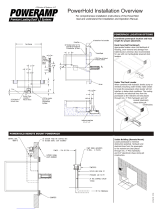
Component Identification
* Some models are equipped with multiple hoist cylinders.
*Powerpack may be mounted on underside of leveler or remotely.
A Lip
B Deck
CLip Cylinder
DFlow Control Valve
EHoist Cylinder*
FStorage Prop Yoke
GProp Kicker (Behind Prop Assy)
HStorage Prop Assembly with Prop Lock Pin
included
IHinge Pins
JStored Limit Switch
KMaintenance Props(2)
H
C
F
D
A
B
E
J
I
G
K
K

9
4111-0008 — April 2017
June 2017
INSTALLATION
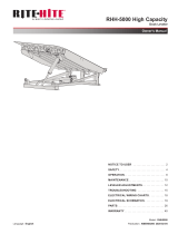
Prepare Pit
A—Distance (Pit Width)
(Front and Rear)
B— Distance (Dock Floor-to-Pit
Floor) (All Four Corners) 1/2”
Taper Rear to Front
C— Distance (Pit Length)
(Both Sides of Pit)
D— Distance (Pit Corner-to-Corner) (Top,
Bottom, and Both Sides)
Before lowering the dock leveler into the pit, the
following must be performed:
1. Remove all debris from the pit and sweep the pit
clean.
2. Check the entire dock leveler pit for proper
construction according to approved/certified
pit drawings. Make sure pit is square, has the
proper depth and taper by making the following
measurements:
• Measure pit width distance (A) at both front
and rear of pit.
• Measure dock floor-to-pit floor distance (B) on
both sides of the rear embed channel and at
front if applicable.
• Measure pit floor taper, rear to front cannot
exceed 1/2” total taper.
• Measure pit length distance (C) at both sides.
• Measure corner-to-corner (criss-cross) distance
(D) at both sides. Take measurements at dock
floor level and at pit floor level.
NOTE” If any measurement are off by more than
1/8 in. (3.18 mm) in depth, width and
squareness 1/4 in + 0 in (6.32mm) contact
Technical Services before proceeding.
3. Make sure the field junction box for the dock leveler
(E) and floor embed plate (F) is at the correct
location per pit diagrams.
Only trained installation professionals with the
proper equipment should install this product.
Post safety warnings and barricade the work area at
dock level and ground level to prevent unauthorized
use of the equipment before installation has been
completed.
B
A
C
B
C
A
D
F
E

10 4111-0008 — April 2017
June 2017
Poweramp dock levelers are designed with
installation in mind. Each unit is shipped with lifting
bracket(s) (A) fastened to the platform.
INSTALLATION
Prepare Dock Leveler
The dock leveler is heavy. Use a lifting device and
chains with the appropriate lifting capacity and
reach.
Always use the lifting brackets provided with the
unit whenever lowering or lifting a dock leveler into
or out of a pit.
A
B
TOLERANCES
(UNLESS OTHERWISE NOTED)
FRACTIONAL: 1/32"
DECIMAL:
.00 = .01"
.000 = .005"
ANGULAR: 1
MATERIAL
DRAWN BY CHECKED BY
DRAWING NO.
DATE
mikemartin 2/4/2015
vs prop
P O W E R A M P
M C G U I R E
D L M
S Y S T E M S, I N C.
L o a d i n g D o c k E q u i p m e n t
This print is the property of Systems, Inc. and represents a proprietary article in which Systems, Inc. retains any and all
patent and other rights, including exclusive rights of use and/or manufacture and/or sale. Possession of this print does
not convey any permission to reproduce, print or manufacture the article or articles shown therein, such permission to be
granted only by written authorization signed by an officer or other authorized agent of Systems, Inc. thereof.
STOCK NO.
FIG.“A”
FIG.“B”
File Name: 1751-0230 Rev E
Decal Size: 3.75 x 6.25
CRUSH HAZARD
DO NOT WORK UNDER OR IN FRONT OF
DOCK LEVELER unless ALL props have been
properly positioned and secured. First position
side maintenance prop(s) and secure with screw
and nut as shown in figure “A” below. Then
position storage prop and secure with prop lock
pin as shown in figure “B” below. Failure to do so
will result in death or serious injury. Refer to
owner’s/user’s manual for proper procedure.
Prop Lock
Pin
Storage
Prop
Stored
Position
Maintenance
Position
Screw and Nut
Maintenance
Prop
1751-0230 Rev E
* Refer to OSHA regulation 1910.146. Confine Space
* Refer to OSHA regulation 1910.147. Lockout/Tagout
A— Lifting Bracket B — Maintenance Props
A
B
B

11
4111-0008 — April 2017
June 2017
Maintenance props in lowered location during installation and service.
1. Remove any control panel, bumpers or pelletizing
that may be banded to the dock leveler. Do not
remove banding on hoist cylinder or storage prop
at this time.
2. Make sure the mounting hardware of lifting
bracket(s) (A) is tight but allows the bracket(s) to
pivot relatively freely on the mounting cap screw.
DO NOT over tighten.
3. Attach lifting chain to lifting bracket(s) (A) and to
a lifting device (i.e., hoist or fork truck) having the
appropriate lifting capacity and reach.
NOTE: Overall length of lifting chain and bracket
(A) must be kept to a minimum to prevent
interference between the lifting equipment
and the building ceiling or door as the dock
leveler is lowered into the pit.
INSTALLATION
Installation of VS levelers from inside is
recommended due to combined height of leveler
and proper lifting equipment may be greater than
outside door height.
A

12 4111-0008 — April 2017
June 2017
4. Before installing the leveler the embed channel
must be shimmed and welded to the embed on
the pit floor.(10 inch deep pit only.)
INSTALLATION
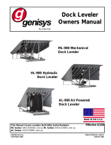
Install Dock Leveler
F
G
H
I
Shim
Stacking Methods
ADistance (Leveler Frame
Height)
BShim Location (Under
Storage Prop) (Standard
Dock Leveler Only)
CDock Floor
DRear Embed Frame
EEmbed Frame (Storage
Prop)
FPyramid (Preferred)
GStepped (Acceptable)
HOffset (Not Acceptable)
IStraight (Not Acceptable)
The minimum size of the shim that contacts the
leveler frame (i.e., the top shim of each shim stack)
must be at least 4-1/2 x 4-1/2 in. (114.3 x 114.3
mm) to support the full width of the hoist cylinder /
storage prop weldment.
Use the thickest shim stock possible for stability
and weld penetration purposes. DO NOT use
multiple layers of 1/8 in. (3.18 mm) or thinner shim
stock.
B
C
D
A
E
E
B
E

13
4111-0008 — April 2017
June 2017
INSTALLATION
7. Once the three hinge pins are installed, install the
Storage prop. Install the prop pin and clip.
Note: Do not connect hoist cylinder at this time.
System must be bleed before connected see
page 17.
5. Lube the three rear hinge pins using grease, install
the three pins in the rear embed only half way
through the first hinge tube.
6. Lower the Vertical leveler down centering the
leveler’s three hinges with the embeds hinges.
• Insert the pins. Start with the outside first
second install the center pin and than the last
hinge pin.
• Optional: Use a bottle jack to align the rear of
the dock leveler to the embed channel.
ARear Embed CMaintenance Props ELifting Lug
BDock Leveler DHinge Pins FStorage Prop
The dock leveler is heavy. Use a lifting device and
chains with the appropriate lifting capacity and
reach.
Always use the lifting brackets provided with the
unit whenever lowering or lifting a dock leveler into
or out of a pit.
A
F
C
B
Bottle Jack
D
C
E

14 4111-0008 — April 2017
June 2017
1. Mount the push button control panel (B) so bottom
of control panel-to-dock floor distance (C) is 48 in.
(1219.2 mm).
2. Install electrical disconnect panel (A) if not already
installed.
3. Install and connect the control wiring.
4. Connect the dock leveler power cable to the field
wires in the pit junction box. Refer to the electrical
drawings supplied with the dock leveler.
INSTALLATION
Install Control Panel and Wiring
B
A
C
D
The electrical power must be OFF prior to electrical
installation. For maximum protection, use an OSHA
approved locking device to lock out all power
sources. Only the person installing the equipment
should have the key to unlock the power source.
DO NOT make any final electrical connections until
all welding has been completed.
All electrical work — including the installation of
the disconnect panel, control panel, and final
connections to the pit junction box — must be
performed by a certified electrician and conform to
all local and applicable national codes.
When drilling access hole in the control box, DO NOT
penetrate too deep, components may be damaged.
DO NOT turn control upside down to drill any access
holes. To prevent damaged to electrical components
from debris cover components prior to drilling
Seal all conduit entrances to prevent moisture from
entering the control box.
DO NOT use compressed air to clean control box.
Recommended to vacuum debris from inside.
1.50"
3.00"
Decal Size: 1.5 x 3
File Name: 1751-0736 Rev A
Arc Flash and
Shock Hazard
PPE [Personal Protection
Equipment] Required
De-energize equipment before
working on or inside. Do not
open cover without appropriate
PPE. Refer to NFPA 70E for
PPE requirements. This panel
may contain more than one
power source.
Hazardous Voltage
Will Result in Death
or Serious Injury
1751-0736 Rev A
A— Disconnect Panel
B— Control Panel
D— Placard
(provided by others)
C— Distance, 48 in. (1219.2 mm)
* Refer to OSHA regulation 1910.146. Confine Space
* Refer to OSHA regulation 1910.147. Lockout/Tagout

15
4111-0008 — April 2017
June 2017
INSTALLATION
Placard Installation Instructions
Control Box
Conduit
Nylon Tie
Placard
• Owner/Users are responsible for the installation and placement of product
placards.
• Make sure placard is in plain view of dock leveler and/or vehicle restraint
operations.
• Suggested placement of placard is near control box attached to electrical
conduit by using nylon tie. If there is no control box present, mount placard
on wall to the immediate left of leveler at eye level.
(Placard placement
shown as reference
only.)

16 4111-0008 — April 2017
June 2017
1. Disconnect the external lifting device and chains
from the lifting brackets.
2. Complete all welding. Clean and paint all welds.
3. Install hydraulic hoses and fill system.
4. Connect all electrical connections .
5. Purge system (see p.17).
6. Connect hoist cylinder (see p.17)
7. Lower dock leveler check to make sure the
leveler goes into float mode (about 15” above
dock floor) allow to dock to float to full below
position. Make sure the dock makes contact with
pit floor. Push and hold the RAISE button until
the leveler turns off and the BLUE stored light
comes on.
8. Check the lip operation: Lower dock leveler
check to make sure the leveler goes into float
mode (about 15” above dock floor) allow to dock
to float to below dock. Push and hold the RAISE
button until the leveler turns off and the Blue
stored light comes on.
9. Install the Placard(s) (D), in close proximity to the
control box and in plain sight.
10. Test leveler for operation.
Put New Dock Leveler Into Service
INSTALLATION
File Name: 1751-0490 REV B
Decal Size: 3 x 2.875
ATTENTION INSTALLER:
Replace rear plug with
breather cap
Do not overfill
Oil should fill ½ site glass
Use ULTRA VIS HVI 15 or
MIL SPEC 5606
Questions Call: 800.643.5424
1751-0490 Rev B
Following start-up or if the platform is raised using
an external lifting device or the hydraulic system
is opened to atmosphere, air will enter into the
hydraulic system.
Whenever this happens, purge air from hydraulic
system fully.
DO NOT grind or weld if hydraulic fluid or other
flammable liquid is present on the surface to be
ground or welded.
DO NOT grind or weld if uncontained hydraulic
fluid or other flammable liquid is present. Stray
sparks can ignite spills or leaks near the work area.
Always clean up the oil leaks and spills before
proceeding with grinding or welding.
Always keep a fire extinguisher of the proper type
nearby when grinding or welding.
DO NOT connect the dock leveler electrical wiring
and ground connections until all welding has been
completed.
DO NOT ground welding equipment to any
hydraulic or electrical components of the dock
leveler. Always ground welding equipment to the
dock leveler frame, NEVER to the platform.
ALWAYS stand clear of dock leveler lip when
working in front of the dock leveler.
Post safety warnings and barricade the work
area at dock level and ground level to prevent
unauthorized use of the dock leveler before
installation has been completed.
Only trained installation professionals with the
proper equipment should install this product.

17
4111-0008 — April 2017
June 2017
INSTALLATION
Rod Eye adjustment & New installation
1. Support the leveler with the maintenance props.
Lock out the storage prop with the prop pin and
clip.
2. Lock-out and tag-out the leveler.
3. Remove lower hoist cylinder mounting pin.
4. Remove one of two screws holding the stored
limit switch. Swivel stored limit switch away from
storage prop.
5. Restore power to the leveler. Confirm the BLUE
stored indicator light is no longer illuminated.
6. Cycle the hoist cylinder up and down at least
once to make cylinder is fully extended.
7. Rod eye should be adjusted so the center of the
rod eye is half way below the center of the hole
of the embed. After adjusted tighten jam nut.
8. To center the rod eye with the embed tap the
lower button until the pin (lube pin) can be
installed. Use washers to keep the rod eye
centered in the opening.
9. After pin has been installed, store maintenance
props and prop pin and clip, test the leveler for
operation.
Purging Air From The VS Hydraulic
System.
1. The unit must be supported in the stored position
with the storage prop and maintenance props in
their in service positions. Lock out the storage
prop with the prop pin and clip.
2. Lock-out and tag-out the leveler.
3. Disconnect the lower hoist cylinder mounting pin.
4. Remove one of two screws holding the stored
limit switch. Swivel stored limit switch away from
storage prop (SEE PAGE 28).
5. Open down speed flow control valve (counter
clockwise). Write down the adjustment. Down
speed control valve is located on hoist cylinder
(SEE PAGE 28).
6. Restore power to the leveler. Confirm the
BLUE Leveler Stored indicator light is no longer
illuminated.
7. Cycle the hoist cylinder up and down at least 6
full times using the LOWER and RAISE buttons.
8. Connect the hoist cylinder to the base of the
embed is channel.
9. Remove the prop pin and clip, return the
maintenance props to the stored position.
10. Adjust down speed flow control to factory
settings. The settings is a leveler down speed
of 15-20 seconds from stored to full below dock
position.
11. The lip cylinder is self purging. Lower the leveler
to a 45 degree angle. Cycle lip by depressing
the LOWER and LIP button together to lower the
lip. Press the raise and lip button together to
raise the lip. WARNING: Stay clear of lip at all
times as it may fall if air is present in the system.
12. Make sure all air is purged from the hydraulic
cylinders after set-up and any time air is
introduced to the system.
File Name: 1751-0138 Rev B
Decal Size: 4 x 2
CRUSH HAZARD
DO NOT REMOVE hydraulic cylinder until leveler is
safely supported by maintenance prop. Refer to
owner’s/user’s manual for proper maintenance
procedure. Failure to comply will result in death or
serious injury. 1751-0138 Rev B
File Name: 1751-0229 Rev E
Decal Size: 4 x 1

18 4111-0008 — April 2017
June 2017
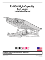
OPERATION
When the leveler is operated an electric motor is
activated (C) which, drives a hydraulic pump. The
hydraulic pump forces oil into the platform cylinder(s)
(D), causing the platform to rise or lower. Releasing
the button will stop the platform from moving (except in
the float mode).
To lower the vertical leveler the LOWER (L) button
will be depressed. The leveler Hoist Cylinder (D) will
extend, an electrical solenoid (H) will activate and
disengage the Storage Prop( not shown). The solenoid
will hold the Storage Prop disengaged for a short
period of time to allow the leveler to lower. The leveler
will start to lower down to the transport vehicle. When
the leveler is about 12” to 15” above dock height the
leveler goes into float mode. You will also hear the
motor make a different sound and you no longer need
to hold the LOWER button. This feature is designed
into the operation of the leveler to allow for the
floating/vertical motion of the transport vehicle during
loading and unloading.
To lower the lip the vertical leveler must not be in the
stored position. Depress the LOWER (L) button and
LIP (K) button at the same time and the motor will
shut off and the lip will lower. To raise the lip, depress
the RAISE (J) button and the LIP(K) button the motor
will run and the lip will raise. The LIP push button is
inactive while the leveler is in the float mode. Also
when leveler is stored.
* Some models are equipped with multiple cylinders.
Theory
AControl Box DHoist Cylinder H Solenoid K Lip Button
B Platform F Limit Switch ILip Cylinder LLower Button
CPower Pack G Reservoir J Raise Button
C
BI
F
G
HD
J
L
A
K
/