Page is loading ...

IO PH PR 12/13
For comprehensive installation instructions of the PowerHold
read and understand the Installation and Operation Manual.
PowerHold Installation Overview
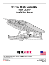
POWERPACK LOCATION OPTIONS
POWERHOLD REMOTE MOUNT POWERPACK
Inside Building (Remote Mount)
Locate powerpack to minimize
obstruction potential. Hydraulic and
electrical lines from the powerpack
to the restraint are best placed
through min. 3” PVC (hydraulic)
and 3/4” (electrical) chase during pit
construction.
Under The Dock Leveler
When combined with hydraulic leveler pump or
remotely mounting under leveler, make certain
to locate the powerpack where leveler will not
interfere in below dock conditions. The routing
of hydraulic and electrical lines from the
powerpack to the restraint are best placed
through min. 3” PVC (hydraulic) and 3/4”
conduit (electrical)
chase during pit
construction.
Allow
Enough
Clearance
for Possible
Seal or
Shelter
Dock Face (Self Contained)
Appropriate location when the likelihood of
flooding, snow removal and damage from
trailer/trucks is minimal. Also recommended
for use with non-hydraulically powered dock
levelers.
Coordinate powerpack location and hose
length for proper placement.

Poweramp • Division of Systems, LLC • W194 N11481 McCormick Dr. • Germantown, WI 53022
800.643.5424 • fax: 262.255.4199 • www.LoadingDockSystems.com
For comprehensive installation instructions read and understand the
Installation and Operation Manual.
PowerHold Installation Overview
A continuing product improvement process is in effect at Systems, LLC. We reserve the right to make product changes without prior notice.
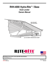
Concrete Dock Face (Standard installation)
Driveway Mount (Recommended when dock face is unsuitable for PowerHold Mounting)
Cantilevered Dock (For bumper projection >4” or cantilevered dock or Edge-of-Dock leveler)
48”
8” Min.
Driveway mount requires attachment to
a concrete drive greater than 8” thick.
For asphalt drive, pour 48”x48”x8”
(min.) concrete pad and include six (6)
3/4” dowels into foundation wall. Then
proceed with adhesive anchors or weld
plate embed.
Determine offset
then proceed with
“Driveway Mount”
instructions below.
20”
20”
Weld three sides of PowerHold back plate to the
optional embed mounting plate (Part #7953-0119)
with continuous 1/4” fillet weld.
5 1/4” minimum
To determine size offset required, take total effective
bumper projection (bumper size plus any cantilever) and
subtract 4”.
48”
8” Min.
Using back plate as a guide, drill six (6) holes
for wedge anchors (3/4”x 5 1/4” min.) (Kit
#2103-0003)
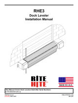
Wedge Anchors Method Drive Embed Method
Wedge Anchors Method Weld Plate Embed Method
36”
14”
Embed
Plate
located 2”
above grade 3/8”
Driveway Mount Wall Mount
Dim. A
Offset Formula
Dim. A Dim. B Offset
Bumper Projection Cantelever
4" + Dim B
6" + Dim B -4" = Offset
10" + Dim B
15" + Dim B
Dim. B
Dim. A
Dim. B
Weld method
Properly locate and level the drive embed weld
plate (Part#7953-0132) in the drive approach.
Observe Cantilever conditions for proper
positioning. Weld restraint to embed plate with a
continuous ¼” filet weld.
(Kit #2103-0003)
Install six (6) 3/4” Dia. x 5 1/4”
min. wedge anchors at the base
of the PowerHold.
Dim. B
Dim. B
48”
For filler requirements from 1 ½”to
7 ½” use cantilever bracket #9414-
0054
weld to
embedded mounting plate (Part
#7953-0119)
For filler requirements for 8 3/4” to
13 3/4” use cantilever bracket
#9414-0055 and anchor cantilever
bracket to the dock face (3/4” Dia.
X 5 1/4” min.) (Kit #2103-0003) or
weld to embedded mounting
Plate (Part #7953-0119).
and anchor cantilever bracket
to the dock face or
/