Page is loading ...

INSTALLATION, OPERATION AND MAINTENANCE MANUAL
Refer to enclosed warranty for operating parameters to ensure proper use with your water supply.
Watts Premier, Inc. 8716 W Ludlow Drive Suite #1 Peoria, AZ 85381
Phone: 800-752-5582 www.premierH2o.com Fax: 623-866-5666
Manual #: 199334 Manual Date:8/06/05
Warning
Please read carefully before proceeding with installation. Your failure to follow any attached instructions or
operating parameters may lead to the product’s failure and possible damage to property.
System Tested and certied by NSF International against ANSI/NSF
Standard 53 for the reduction of claims specied on the performance
data sheet.
MODEL
Ultra-UV-R

Thank you for your purchase of a UV-R system. With proper installation and maintenance,
this system will provide you with high quality water for years to come. All of Watts Premier’s
water enhancement products are rigorously tested by independent laboratories for safety and
reliability. If you have any questions or concerns, please contact our customer service depart-
ment at 1-800-752-5582 (outside USA 480-675-7995) or refer to our online troubleshooting
at www.premierH2o.com.
Table of Contents
Mainteance Record .....................................................................................................
Operational Parameters ..............................................................................................
Contents of Ultra UV-R System ....................................................................................
Tools Recommended For Installation .........................................................................
Installation .....................................................................................................................
Faucet Installation...........................................................................................................
Adapt A Valve Installation...............................................................................................
UV Lamp Replacement ................................................................................................
UV-R Diagrahm..............................................................................................................
Preformance Data ........................................................................................................
Warranty ........................................................................................................................
Service Record
Date of Purchase:__________ Date of Install:_________ Installed by:____________
DATE FILTER DATE FILTER DATE FILTER
3
3
3
3
3
4
5
6
7
8
9
2
NOTES:

Do not use with water that is microbiologically unsafe or of unknown quality, without adequate
disinfection before or after the system. Installation needs to comply with state and local plumbing
regulations.
Operational Parameters
1 Ultra-UV-R system
1 120V/60Hrz Transformer
1 Manual and Warranty Card
If any of the items are missing please contact Watts Premier prior to installing.
Tools Recommended For Installation
√ small knife
√ variable speed Drill
√ 1/8” (3 mm), 1/4” (6.4 mm) and 7/16” (11.0 mm) drill bits
√ 1/2” and 5/8” open-ended wrenches (or adjustable wrenches)
√ Phillips screwdriver
Contents of Ultra- UV-R System
Installation
Step 1.
Locate a space under the sink that allows the unit to be mounted close to the cold
water supply and allows for easy access during maintenance and lter changes.
System must be installed to the cold water supply only. Allow 2” (5cm) clearance
between the bottom of the lter housing and the oor of the sink cabinet.
Using the mounting hole on the bracket, mark the location for the mounting screws on
the cabinet wall under the sink.
Screw the (2) screws into the wall at the marked location. The Ultra-UV-R bracket is
designed to be mounted without removing the screws. Hang the Ultra-UV-R-2 module
on the screws using the mounting holes in the bracket.
Step 2.
Special Note: Porcelain sink surface material is extremely hard and can crack or chip
quite easily. Use extreme caution if drilling. Watts Premier accepts no responsibility for
consequential damage resulting from the installation of faucet to the sink or counter top.
Colored faucets can be ordered through Watts/Premier’s toll-free customer service
department by calling 1-800-752-5582 in the Continental United States, online at
www.
premierH2o.com or 480-675-7995 outside the United States.
3
Maximum Minimum
Operational Temperature 100°F (37.8°C) 40°F (4.4°C)
Operating Pressure 100 psig (7.43 g/cm²) 20 psig (1.406 kg/cm²)
pH Parameters 10 5
Flow Rate 0.5 GPM @ 60 psig

A. Remove faucet kit from plastic bag and locate each of the following parts (as shown in Figure A)
Note: Remove plastic tubing from faucet body before inserting long
reach spout into faucet body.
Note: If using existing hole (sprayer or soap dispenser) go to
Step G.
A. Determine desired location for the faucet on your sink surface.
B. Place a piece of masking tape or duct tape on location where the hole
is to be drilled. Mark the center of the hole on the tape.
Note: Stainless steel sinks go to Step F.
Porcelain Sinks
C. Using the variable speed drill on the slowest speed, drill a 1/8” (3.0
mm) pilot hole at the center of the desired location. Use lubricating
oil or liquid soap to keep the drill bit cool while drilling. Note: If
drill bit gets hot it may cause the porcelain to crack or chip. Pilot
hole must be drilled through both porcelain and metal casing of the
sink before proceeding to the next step.
D. Enlarge pilot hole to ¼” (6.4 mm). Keep drill speed on the slowest
speed and use lubricating oil or liquid soap to keep drill bit cool.
E. Enlarge the ¼” hole to 7/16” (11.13 mm). Keep drill speed on the
slowest speed and use lubricating oil or liquid soap to keep drill bit
cool.
F. Pass the Escutcheon plate and black rubber washer over threaded
mounting tube at the base of the faucet body.
G. From top of sink pass the threaded mounting tube through the hole
drilled in the sink. Align the faucet body.
H. From under the sink, slide the locating washer and the lock-washer
over the threaded part of the faucet tube. Screw on retaining nut.
Tighten with wrench.
Connect the loose end of the ¼” blue plastic tubing from the ltration unit
to the threaded mounting tube of the faucet as shown in Figure B.
Figure B: Faucet tube connection
Figure A: Faucet tube connection
4
Faucet threaded
mounting tube
Brass insert goes inside
of tubing
Brass compression nut
Delrin sleeve beveled
end faces end of tubing
Blue tube

Installation of Upgraded Adapta Valve
For 3/8” Plumbing For ½” Plumbing
Step 1 Turn off the cold water supply to the faucet by turning the
angle stop valve off.
Step 2 Attach the Adapta Valve as illustrated in the photo above. When
attaching to straight pipe threads, use Teon tape on the threads.
Step 3 Attach the Green tube into the Adapt Valve Securing the connection
Hot water supply Cold water supply
line line
Step 3.
5
#134007

Warning: Do not touch UV Lamp or Quartz Tube with bare ngers or hands. Fingerprints
on the lamp or tube may reduce lamp effectiveness. Handle with clean cloth or
gloves.
A. Unplug ballast from GFCI electrical outlet.
B. Unplug the plastic electrical connector from ballast to UV Lamp.
C. Turn off water supply to the unit. Lift faucet handle to relieve water pressure.
D. Disconnect both ¼” plastic tubes from the UV housing body by turning the white plastic nuts
counter clockwise. Remove the UV housing from the single mounting clip.
E. Unscrew UV cap counter clockwise.
F. Using a at bladed screwdriver remove UV lamp from cap and discard. Discard cap & quartz
tube if replacing at the same time as lamp.
G. Clean inside of UV housing with warm soapy water. Rinse with warm clean water to remove
soap.
H. Lubricate UV housing o-ring with a water-soluble lubricant (i.e. K-Y Jelly ® or Silicone lubricant)
NOTE: Do not use Petroleum based lubricants such as Vaseline ®.
I. Carefully slide new UV lamp into the cap and make sure the end plug is sealed. Water cannot
come into direct contact with the UV lamp.
J. Screw UV cap back on to UV housing body carefully by turning clockwise.
K. Snap UV housing body back into single mounting clip. Reconnect the ¼” blue tubing back on to
the UV housing body.
L. Repeat Step 4: Startup.
Step 4 Lift black faucet handle up on faucet to start ow of water through unit. Run 7 gallons
of water through unit. Close faucet. Note: You may hear some noise as air
is being purged from the unit and the rst few glasses of water through
the unit may be dark in color due to carbon nes.
B. Check for leaks. If you have any leaks, shut-off water supply to system, repair
and restart unit.
C. Connect plastic electrical connector from UV unit to the plastic electrical
connector from AC adapter.
D. Plug adapter into GFCI electrical outlet. You will see a pale blue light from the
view port on the UV Housing body. The light indicates that the UV lamp is on
and working.
Do not unplug UV unit from power supply. Turning system off & on will shorten the life of the
UV lamp. UV should be on continuously for maximum effectiveness.
The system requires a warm-up period for proper operation. Wait 20 minutes after plugging
in the system before using water.
Water not drawn from unit for a period of time may have a taste or odor and will be warm. To
avoid this, allow water to run through the system for one minute before using.
Important guidlines
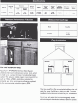
Replacement lters for this and many other ltration systems can be purchased directly
from Watts Premier. Ordering options include mail order, telephone ordering, and online
lter replacement. Additionally, Watts Premier sells ltration and reverse osmosis systems
suitable for almost any individual or commercial application.
Replacing UV lamp, Cap & Quartz Tube
6

Figure E: UV Tube Assembly & Exploded View
7
Item
Part # Des c ript ion Item Part #
Descript ion
1 134008 Easy Tap Adapter 17 Faucet Body
2 131017 Insert Brass 114" 18 116032 L/R Spout
3 131012 Sleeve Delrin 114" 19 137046 UV- Bracket
4 131002 Nut Brass 114"C 20 146001 #10-3/4" Philip Pan Head Screws (6)
5 140007 Tubing 114"Green (4ft) 21 146004 # 10-1" Philip Pan Head Screw (2)
6 125034 Elbow 90° 1I4"Cx 1/4" MPT (6) 22 164004 Single Mounting Clip
7 113004 Lid Black 114"FPT 23 104015 CTG-10" 5 Micron Sediment
8 113029 0- Ring For Filter Housing 24 Module Includes:
9 101015 P-CB-l I-Micron Carbon Block 170001 Body, Cap, Quartz tube, O-ring
a Gasket for Carbon Block (2) & UV lamp
10 113017 Filter Housing 10" Blue 27 170019 UV-Rep1acement Lamp(ST-200 UV lamp)
11 140004 Tubing 114"Blue (4ft) 28 Ballast
12 Nut 170007 1O0v./50Hz.
13 Lock Washer 170010 120v./60Hz.
14 Black Locating Washer 170014 220v./50Hz.
15 116047 Black Rubber Washer 170015 240v./50Hz.
16 116053 Escutcheon Plate

8
Watts Premier, Inc.
8716 W Ludlow Drive Suite #1
Peoria, AZ 85381 – USA
Performance Data Sheet for specic claims to NSF Std-53.
CT-1, UC-1, UC-2 & Ultra-UV-R
GENERAL USE CONDITIONS:
1: System to be used with municipal or well water sources treated and tested on regular basis to insure bacteriological safe
quality. DO NOT use with water that is microbiologically unsafe or unknown quality without adequate disinfection before
and after the system. “Systems certied for cyst reduction may be used on disinfected water that may contain lterable
cysts.”
2: Operating Temperature: Maximum 100
o
F (40.5
o
C) Minimum 40
o
F (4.4
o
C)
3: Operating Water Pressure: Maximum 100-psi (7.43 kg/cm
2
) Minimum 20-psi
4: Turbidity: < 5 NTU
5: pH: 5 to 10
6: Maximum ow Rate: 0.50 gpm (1.89 lpm)
RECOMMENDED REPLACEMENT PARTS AND CHANGE INTERVAL:
Note: Depending on incoming feed water conditions replacement time frame may vary.
Description Units Change time Frame
Stage 1: sediment: 5M-10 UC-2 & Ultra-UV-R 6 Months or 1350 gallons of water
1 Micron Carbonblock P-CB-1: CT-1, UC-1, UC-2 & Ultra-UV-R 6 Months or 1350 gallons of water
170019 UV Replacement Lamp Ultra-UV-R 12 months or 9000 hours
Testing parameters: Flow rate 0.5 gpm pH 6.5 and 8.5 Water pressure: 50 psi.
Cyst Reduction Gallons Inuent Efuent 1 Efuent 2
Inuent Avg. 155500 count/ml Fourth Cycle 98000 15 44
Efuent Avg. 28 count/ml 25% 94000 4 15
Percent Reduction 99.98 % 50% 160000 9 39
Maximum Efuent 81 count/ml 75% 270000 17 81
Lead Reduction 6.5 pH Gallons Sample Pt Inuent Efuent 1 Efuent 2
Inuent Avg. 0.16 mg/l 0 Start-up 0.16 0.001 0.0013
Efuent Avg. 0.0024 mg/l 675 75% 0.16 0.001 0.001
Percent Reduction 98.5 % 1350 100% 0.16 0.0031 0.001
Maximum Efuent 0.0088 mg/l 2025 150% 0.17 0.0047 0.001
2430 180% 0.17 0.0088 0.001
Lead Reduction 8.5 pH Gallons Sample Pt Inuent Efuent 1 Efuent 2
Inuent Avg. 0.16 mg/l 0 Start-up 0.16 0.0017 0.01
Efuent Avg. 0.0032 675 75% 0.16 0.001 0.001
Percent Reduction 98 % 1350 100% 0.17 0.001 0.001
Maximum Efuent 0.01 mg/l 2025 150% 0.14 0.0033 0.0058
2430 180% 0.16 0.0058 0.0011
That the systems conform to ANSI/NSF 53 for specic performance claims as veried and substantiated by test data.
REFER TO OWNER’S INSTALLATION/SERVICE MANUAL FOR FURTHER MAINTENANCE REQUIREMENTS, AND WARRANTY
INFORMATION.
Phone: 480-675-7995 Fax: 623-866-5666

8716 W Ludlow Drive Suite #1 • Peoria, AZ 85381
Limited Warranty
What your Warranty Covers:
If any part of your WATTS PREMIER Ultra UV-R is defective in workmanship (excluding replaceable lters, and uv-bulbs),
return unit after obtaining a return authorization (see below), within 3 year of original retail purchase, WATTS PREMIER will
repair or, at WATTS PREMIER’S option, replace the system at no charge.
How to obtain Warranty Service:
For warranty service, call 1-800-752-5582 for a return authorization number. Then, ship your unit to our factory, freight and
insurance prepaid, with proof of date of original purchase. Please include a note stating the problem. Premier will repair it,
or replace it, and ship it back to you prepaid.
What this warranty does not cover:
This warranty does not cover defects resulting from improper installation, (contrary to WATTS PREMIER’S printed
instructions), from abuse, misuse, misapplication, improper maintenance, neglect, alteration, accidents, casualties, re,
ood, freezing, environmental factors, water pressure spikes or other such acts of God.
This warranty will be void if defects occur due to failure to observe the following conditions:
1. The Ultra UV-R System must be hooked up to a potable municipal or well cold water supply.
2. The pH of the water must not be lower than 5 or higher than 10
5. The incoming water pressure must be between 20 and 100 pounds per square inch.
6. Incoming water to the Ultra UV-R cannot exceed 100 degrees F (40 degrees C.)
7. Incoming TDS/Total Dissolved Solids not to exceed 1800 ppm.
8. Do not use with water that is micro-biologically unsafe or of unknown quality without adequate
disinfection before or after the system.
This warranty does not cover any equipment that is relocated from the site of its original installation.
This warranty does not cover any equipment that is installed or used outside the United States of America and Canada.
LIMITATIONS AND EXCLUSIONS:
WATTS PREMIER WILL NOT BE RESPONSIBLE FOR ANY IMPLIED WARRANTIES, INCLUDING THOSE OF MERCHANTIBILITY
AND FITNESS FOR A PARTICULAR PURPOSE. WATTS PREMIER WILL NOT BE RESPONSIBLE FOR ANY INCIDENTAL OR
CONSEQUENTIAL DAMAGES, INCLUDING TRAVEL EXPENSE, TELEPHONE CHARGES, LOSS OF REVENUE, LOSS OF TIME,
INCONVENIENCE, LOSS OF USE OF THE EQUIPMENT, AND DAMAGE CAUSED BY THIS EQUIPMENT AND ITS FAILURE TO
FUNCTION PROPERLY. THIS WARRANTY SETS FORTH ALL OF PREMIER’S RESPONSIBILITIES REGARDING THIS EQUIPMENT.
OTHER CONDITIONS:
If WATTS PREMIER chooses to replace the equipment, WATTS PREMIER may replace it with reconditioned equipment. Parts used in
repairing or replacing the equipment will be warranted for 90 days from the date the equipment is returned to you or for the remainder of
the original warranty period, whichever is longer. This warranty is not assignable or transferable.
YOUR RIGHTS UNDER STATE LAW:
Some states do not allow limitations on how long an implied warranty lasts, and some states do not allow the exclusion or limitation of
incidental or consequential damages, so the above limitations or exclusions may not apply. This warranty gives you specic legal rights,
and you may have other legal rights which vary from state to state.
9

Watts Premier, Inc. 8716 W Ludlow Drive Suite #1 Peoria, AZ 85381
Phone: 800-752-5582 www.premierH2o.com Fax: 623-866-5666
/