Secciones Una Sección Dos Secciones
Número de Modelo Laterales Intactas Lateral Retirada Laterales Retiradas
Todas menos
5 A* 4 A* 3 A*
el SFSQ-LF
*Carga máxima de la combinación del ventilador y la luz
English on reverse
Lutron Electronics Co., Inc.
7200 Suter Road
Coopersburg, PA 18036-1299, U.S.A.
Hecho e impreso en EE.UU., 9/01 P/N 033-039 Rev. C
Controles Para Luz y Ventilador
FS-5E: Máximo 5 A 120 V~ 60 Hz SFS-5E: Máximo 5 A 120 V~ 60 Hz
GFS-5E: Máximo 5 A 120 V~ 60 Hz SFS-5EA: Máximo 5 A 120 V~ 60 Hz
SFSQ-LF: Ventilador: 1,5 A, Luz: 360 W 120 V~ 60 Hz
Notas Importantes
Favor de leer antes de instalar.
1. Precaución: Para evitar un recalientamiento o el posible daño a otros equipos, no instale para
controlar receptáculos, accesorios fluorescentes, equipos motorizados, o equipos subministrados por
transformadores.
2. Los controles requieren alambres separados, en la caja de embutir, para el ventilador y la luz.
3. Para instalaciones nuevas, use un interruptor de ensayo antes de probar el control.
4. Fije ventiladores de varias velocidades en la más alta antes de instalar controles.
5. Use un SFSQ-LF solamente para ventiladores de paletas. Use solamente un control silencioso por
cada ventilador de paletas.
6. Use un FS-5E, GFS-5E, SFS-5E, ó un SFS-5EA solamente con ventiladores indicados “Probados
para uso con controles de velocidad de estado sólido”.
7. No conecte un SFSQ-LF en un circuito con un cortacircuito o receptáculo de GFCI.
8. Durante la operación normal, el control puede estar tibio al tacto.
9. En caso de no existir previsiones para la conexión de tierra en la caja de embutir, la regla "NEC 380-
9 de excepción a (b)" permite la instalación de un control de reemplazo sin conexión a tierra. En este
tipo de instalación, el conductor verde de tierra del control debe ser eliminado o aislado. Todo control
instalado de acuerdo con esta regla de excepción debe quedar cubierto con una placa de pared de
plástico no combustible, aprobada por UL.
10. Instale de acuerdo a los códigos nacionales y locales gobernando la electricidad.
11. Limpie la unidad con un
paño suave y húmedo únicamente
. No use agentes químicos de limpieza.
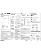
Instalaciones de Unidades Multiples
Cuando combine controles en la caja de embutir, elimine todas las secciones laterales internas antes de
conectar los alambres. Vea el diagrama siguiente. Use un alicate para doblarlas cuidadosamente hasta
que se despeguen. Los controles FS-5E, GFS-5E, SFS-5E y SFS-5EA requieren reducción en
capacidad. Consulte la tabla siguiente para la capacidad máxima del control. El SFSQ-LF no requiere
reducción de capacidad.
Elimine todas las secciones
laterales internas (sombreadas).
Asistencia Técnica
Si tiene preguntas referentes a la instalación o operación de este producto, llame a
Lutron Technical Support
Center
. Por favor suministre el numero exacto del modelo con su llamada.
(800) 523-9466 (EE.UU., Canadá, y el Caribe), para México, llame (001) 888-235-2910
de otros países, llame (610) 282-3800
Fax (610) 282-3090 Internet: www.lutron.com
Garantía Limitada
(Valido solamente en Estados Unidos, Canada, Puerto Rico, y el Caribe.)
Lutron reparará o reemplazará, a su criterio, cualquier unidad cuyos materiales o fabricación resulten defectuosos en el término de un año después de la fecha
de compra. Para obtener servicio de garantía, la unidad debe devolverse al lugar de compra o enviar, con franqueo pago, a Lutron, 7200 Suter Road,
Coopersburg, Pennsylvania 18036-1299.
ESTA GARANTÍA SE OFRECE EN LUGAR DE CUALQUIER OTRA GARANTÍA EXPRESA. LA GARANTÍA IMPLÍCITA DE COMERCIABILIDAD ESTÁ
LIMITADA A UN AÑO, A PARTIR DE LA FECHA DE COMPRA. ESTA GARANTÍA NO CUBRE LOS COSTOS DE INSTALACIÓN, DESMONTAJE NI
REINSTALACIÓN. TAMPOCO CUBRE DAÑOS RESULTANTES DE UN USO IMPROPIO O ABUSO, NI DAÑOS DEBIDOS A UNA INSTALACIÓN O
CONEXIÓN INCORRECTA. ESTA GARANTÍA NO CUBRE DAÑOS INCIDENTALES NI RESULTANTES. LA OBLIGACIÓN DE LUTRON CON RESPECTO A
CUALQUIER RECLAMACIÓN POR DAÑOS RELACIONADOS CON LA FABRICACIÓN, VENTA, INSTALACIÓN, ENTREGA, USO, REPARACIÓN O
REEMPLAZO DE LA UNIDAD, NO SUPERARÁ, EN NINGÚN CASO, EL PRECIO DE COMPRA.
Esta garantía otorga derechos legales específicos, pero se podría tener otros derechos, que varían de un estado a otro. Algunos estados no permiten la
exclusión o limitación de daños incidentales ni resultantes, ni limitaciones en la duración de una garantía implícita, por lo cual es posible que las limitaciones
mencionadas anteriormente no correspondan en ciertos casos.
Este producto puede estar cubierto por la patente Mexicana 168,884 y uno o más de los patentes 4,883,277; 4,835,343; 4,835,816; 5,191,971; y 5,293,103 de los
Estados Unidos y por patentes extrangeros correspondientes. Lutron es una marca registrada de Lutron Electronics Co., Inc.
© 2001 Lutron Electronics Co., Inc.
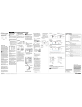
Instalación
Para instalaciones múltiples en una caja de embutir, antes de empezar
consulte las instrucciones para unidades múltiples.
Paso 1 Cuidado: Apague la corriente en la caja de circuitos o
remueva los fusibles.
ON
OFF
ON
OFF
ON
OFF
Aleta
rayada
Alimentación
(Vivo)
A la luz
Al
ventilador
Etiqueta
Dele vueltas a los
tornillos para soltarlos.
Marque el alambre que está conectado al
costado de alimentación del interruptor (el
costado con la aleta rayada).
Paso 5 Conecte el control:
• Conecte el alambre verde o de
tierra desnudo en el control al
alambre de tierra de color
verde o de cobre desnudo en la
caja de embutir.
• Conecte el alambre negro en el
control al alambre removido del
interruptor, que está marcado
con una etiqueta.
• Conecte el alambre rojo del
control al alambre que va al
ventilador.
• Conecte el alambre amarillo del
control al alambre que va la a
la luz.
Paso 6 Monte y alinie el control. Instale la placa de pared.
Paso 7 Encienda la corriente.
ON
OFF
ON
OFF
ON
OFF
Negro
Verde o
desnudo
Tierra
Rojo
Amarillo
Etiqueta
120V
60Hz
Vivo
Neutral
Amarillo*
Rojo
Negro
Tierra
Verde o
desnudo
Luz
Ventilador
*
Tape el alambre Amarillo si no se usará la luz.
Alinie control y apriete
los tornillos.
Coloque los
tornillos.
Use un
destornillador
pequeño para
ajustar la
velocidad mínima
(consulte las
instrucciones en
la parte delantera
del control).
SFS-5E & SFS-
5EA: Gire la rueda
hacia abajo para
subir la velocidad
mínima, o hacia
arriba para disminuir
la velocidad mínima
(consulte las
instrucciones en la
parte delantera del
control).
GFS-5E
FS-5E
Ubicación del «trimpot»
Nota: Si este ajuste tiene un efecto mínimo en la velocidad del ventilador, deje el
ajuste como llegó de fábrica.
Ajuste de velocidad mínima del ventilador
Enciende el control a su nivel mínimo, usando los pasos siguientes: FS-5E:
Fije el pomo completamente hacia la derecha; GFS-5E, SFS-5E y SFS-5EA: Baje el
deslizador hasta el punto inmediatamente antes del apagado. Espere dos minutos.
Si el ventilador se para, ajuste la velocidad mínima: Gire el «trimpot» o la rueda
pequeña (consulte el dibujo) hasta que el ventilador esté en la velocidad deseada.
Este proceso no es necesario para el SFSQ-LF.
No elimine las secciones
laterales éxternas.
Paso 4 Desconecte los alambres del interruptor.
Paso 3 Verifique la aplicación. Este atenuador se monta en una
caja de embutir sencilla y controla, independientemente, con
dos deslizadores, un ventilador de paletas y una luz. Tiene
que existir un alambre para la luz y otro para el ventilador,
además del alambre de alimentación.
Paso 2 Retire los tornillos de montaje del interruptor. Saque el
interruptor de la pared.
Instrucciones importantes de cableado
Tuerza el conectador de
alambre hasta que este
firme.
Asegúrese que no
queden alambres
expuestos.
Cuando se conecten cables, la longitud expuesta de los extremos y la combinación de
conexiones deberán estar de acuerdo con las recomendaciones para el conector
suministrado. Nota: Los conectores suministrados son apropiados para
alambres de cobre
únicamente.
Consulte a un electricista en caso de usar conductores de aluminio.
Pequeño:
Alambres de 14 AWG: quite la aislación en 3/8" (10 mm)
del extremo
Alambres de 16 ó 18 AWG: quite la aislación en
1/2" (13 mm) del extremo
Úselos para conectar un cable de suministro de 14 AWG
con un cable de control de 16 ó 18 AWG
Grande:
Alambres de 10, 12 ó 14 AWG: quite la aislación en
1/2" (13 mm) del extremo
Alambres de 16 ó 18 AWG: quite la aislación en 5/8"
(16 mm) del extremo
Úselos para conectar uno o dos cables de suministro
de 12 ó 14 AWG con un cable de control de 10, 12,
14, 16 ó 18 AWG
Pequeño
Grande
120/127 V
60 Hz